Introduction
This guide describes how to install the Brickstuff lamp post kit for the LEGO Icons Eiffel Tower. This is an add-on to our Premium light kit for the Tower.
Tools
No tools specified.
Parts
-
-
There are several ways to read this guide:
-
Reading it on the web in your browser.
-
Downloading a PDF copy of the guide. You can do this by selecting "Download PDF" as shown by the red rectangle in the first photo. Click on the Options heading in the upper right corner of the screen (see the green rectangle).
-
In the "Dozuki" application, which is available for download from the Apple App Store and various Android and Google marketplaces.
-
If you view this guide in the Dozuki app, search for "Brickstuff" the first time you open the app, then select "Product Guides" from the categories listed under Brickstuff. Scroll down to find this guide.
-
You can also translate this guide into another language when viewing on the web. To do this, install a translator extension into your browser and use that extension/plug-in to translate the page. Using the main Google translate website (translate.google.com) does not work.
-
-
-
The lamp post add-on kit is meant to be installed after you have installed the main light kit for your Eiffel Tower. Make sure you have installed those lights first, and that the main light kit is functioning correctly, before installing this add-on kit.
-
The photo for this step shows the parts included with your add-on kit:
-
The five bags shown by the blue arrows in the photo have 10 "Microflex" LED lights inside each bag.
-
The bag shown by the yellow arrow contains four BRANCH12X driver boards and control cables for connecting everything together, and connecting to the main controller.
-
A total of 48 LED lights are needed for the lamp posts. Your kit includes 50 lights-- the two extra LEDs are in case any lights become damaged during installation.
-
-
-
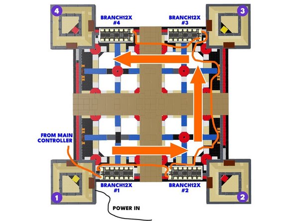
The illustration for this step shows the connections for cables and adapters. You can click on the illustration to enlarge it if needed.
-
Note that each "pillar" of the Eiffel Tower base is numbered in the illustration from 1 to 4, beginning in the lower left-hand corner and moving counter-clockwise from there.
-
Pillar #1 is the location where your USB-C power connector is located, and it's the same place you began from when installing the main light kit for your Tower.
-
In the following steps, you will connect the lamp posts to the BRANCH12X driver boards, then connect the driver boards in a chain beginning with pillar #1 and running to pillar #4. You will also connect the first BRANCH12X driver board to the output on the main controller.
-
-
-
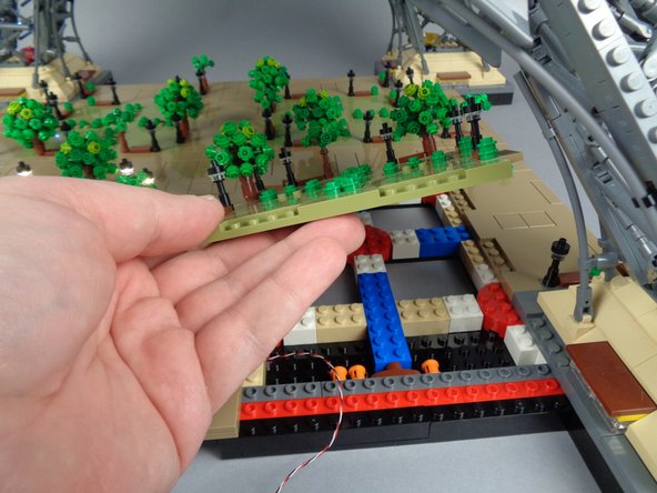
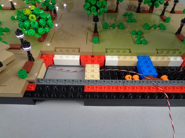
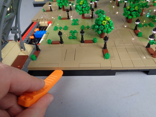
Before beginning installation of your lamp posts, make sure to disconnect all control wires between sections of your Eiffel Tower, and remove the top two sections.
-
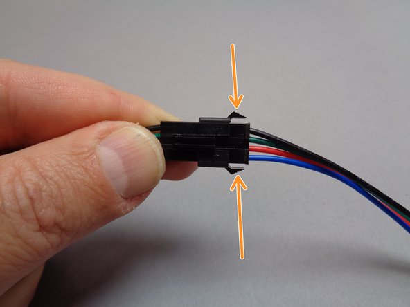
The orange arrows in the second and third photos for this step show how to disconnect the control wires between the sections of your Tower.
-
To disconnect, press down on the latch on the top of the plug as shown in the second photo while at the same time pressing in on the two tabs on the side of the plug as shown in the third photo.
-
Pull the two halves of the plug apart to disconnect.
-
-
-
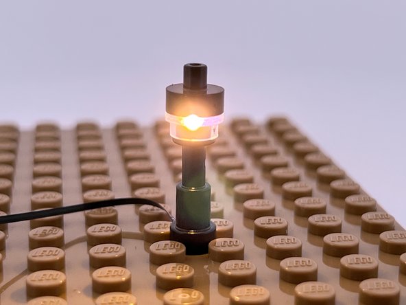
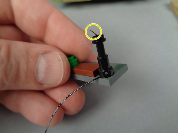
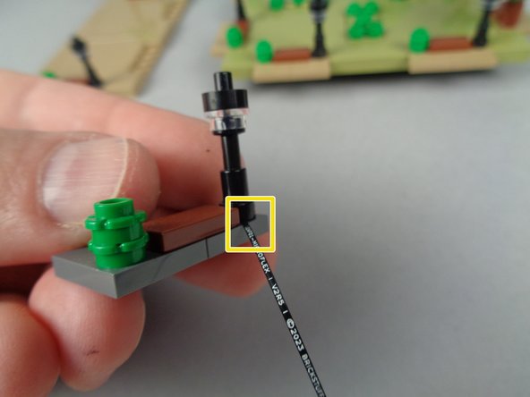
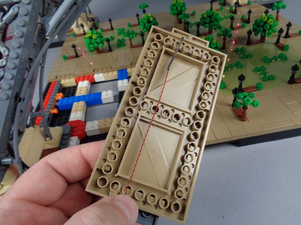
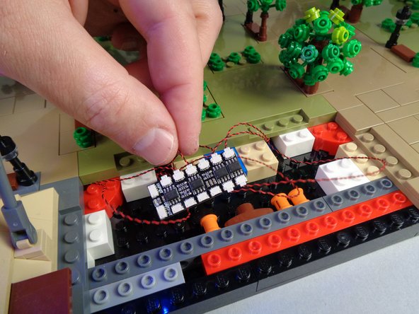
The Microflex LED lights included with your kit are small enough to fit through the center of your Eiffel Tower's lamp posts, but to minimize the chance of damage during installation, it is important to follow some basic rules.
-
The yellow arrows in the first photo for this step show how you will pass the Microflex LED light through the bottom of each lamp post, then up through the hole in the center and out the top.
-
As you can see in the first photo, the end of the Microflex LED light will need to be bent slightly to allow the top plate to attach as shown in the second photo.
-
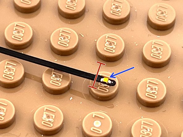
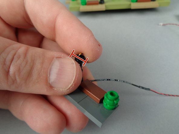
Pay close attention to the third photo in this step. The red line shows where you can bend the LED light. DO NOT BEND ANY CLOSER TO THE END, OR AT THE LED LIGHT CHIP ITSELF.
-
The blue arrow in the third photo shows the tiny light chip on the end of the Microflex LED. If you bend here, the light chip is likely to break loose, damaging the light. A broken light cannot be repaired.
-
While you can use the tweezers included with your kit to bend the light, never bend by holding the LED chip itself. Always hold below the light chip, and bend as little as possible.
-
If you damage more than two Microflex lights during installation, you can purchase additional lights in packs of four from our website.
-
-
-
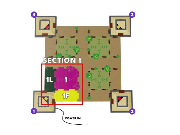
As shown in the first illustration for this step, you will begin your lamp post installation with Section 1 (this is the same section as where your USB-C power connects).
-
Throughout this guide, you will see sections of the Tower base referred to by number (1,2,3,4) and also by location:
-
The green section "1L" in the illustration refers to the left-facing panel of Section 1.
-
The yellow section "1F" in the illustration refers to the front-facing panel of Section 1 ("front" means facing you as you work).
-
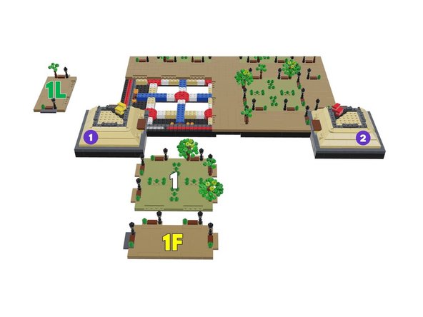
As shown in the second illustration for this step, you will begin by removing the three large panels that make up Section 1.
-
-
-
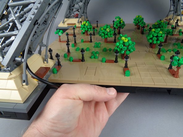
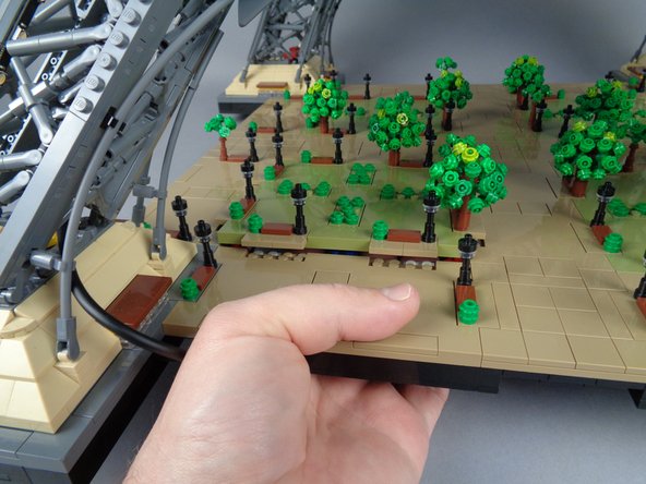
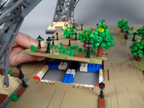
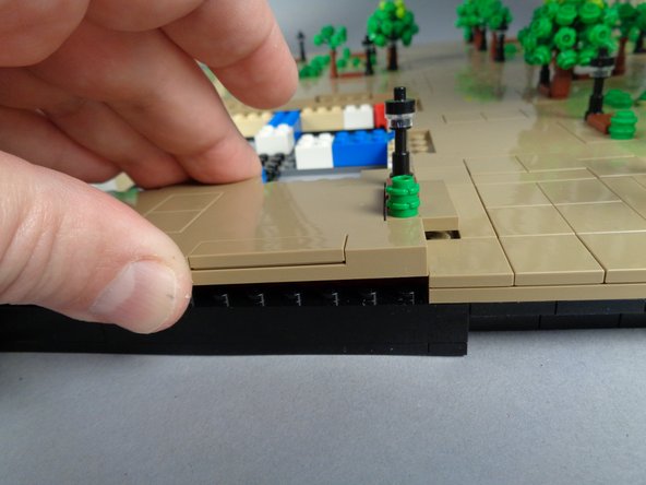
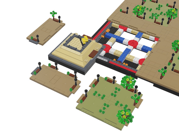
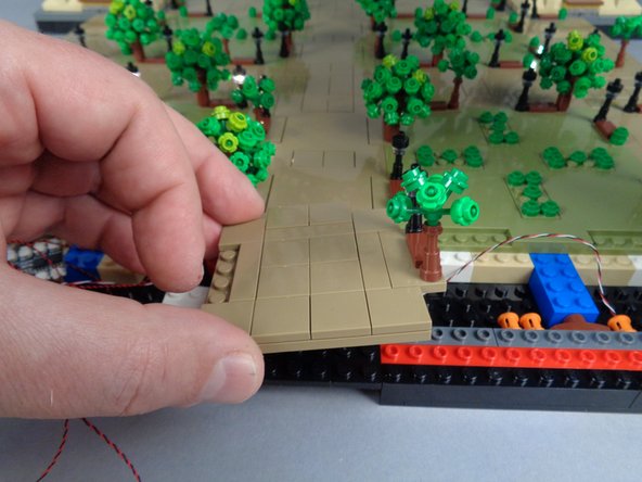
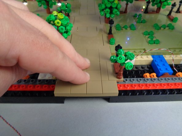
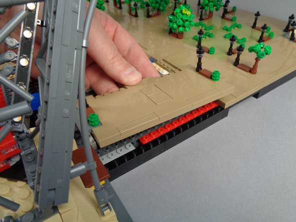
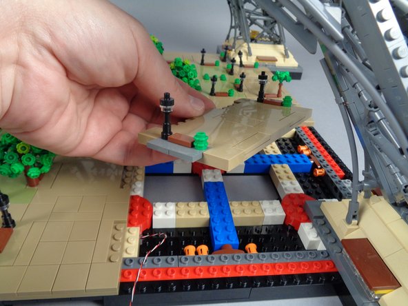
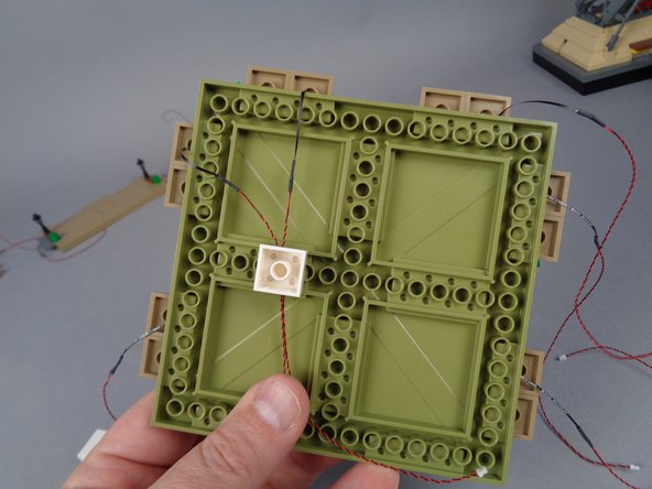
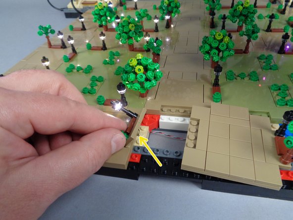
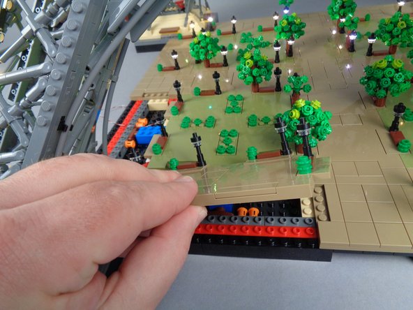
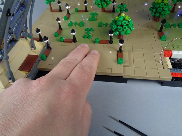
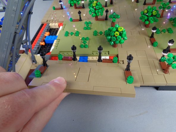
The photos in this step show how you can remove individual panels for each section as you work.
-
Carefully press up from underneath the bottom of your Tower base to loosen a panel. You may need to press hard at first to loosen it.
-
As shown in the third photo for this step, when you remove a panel, be careful to keep it facing the same direction as it was when you removed it.
-
-
-
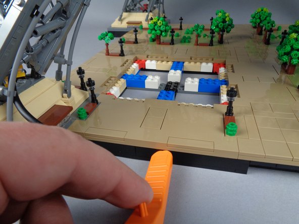
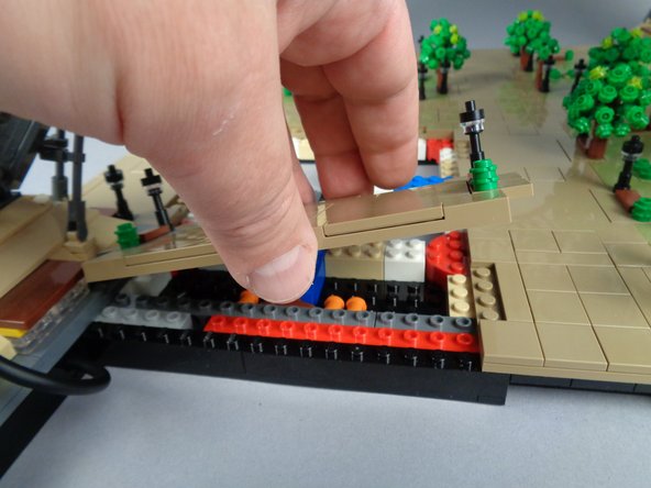
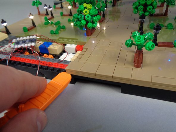
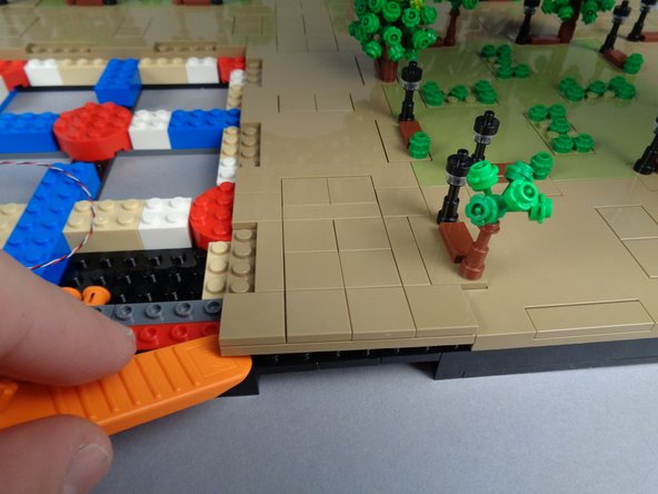
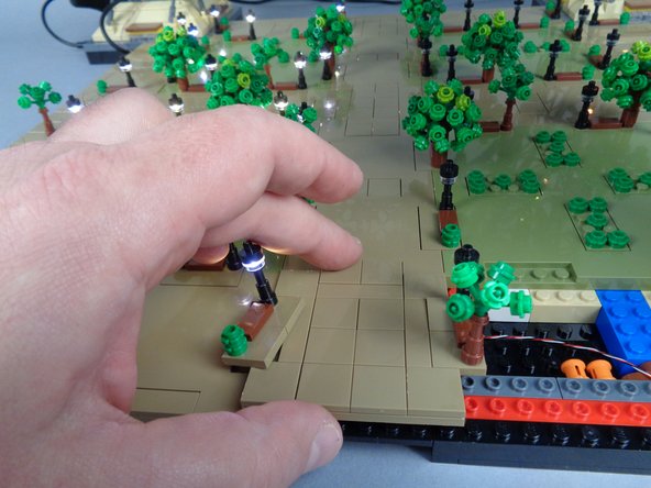
The photos for this step show how you can use your LEGO brick separator to help loosen edge panels, where you are not able to press from beneath.
-
Panels are likely to be attached tightly, so work slowly and loosen especially hard-to-remove panels from multiple locations.
-
-
-
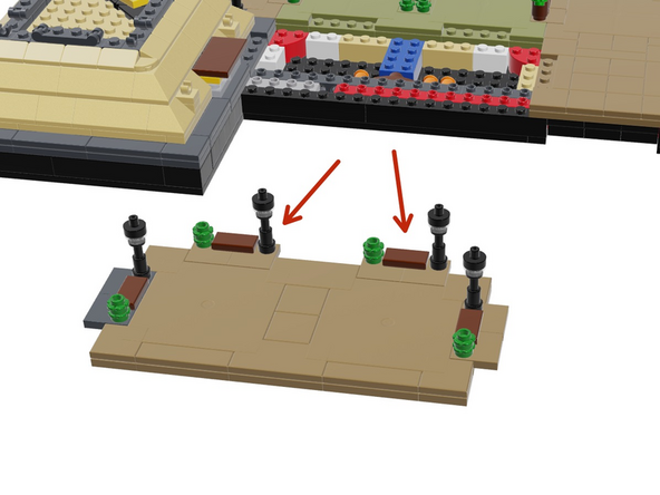
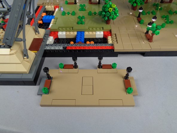
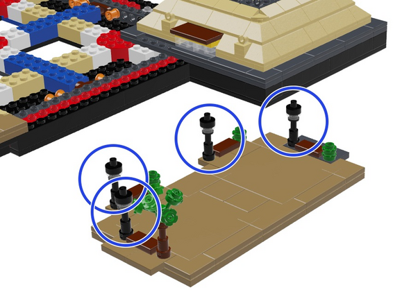
As shown in the illustration for this step, begin by removing Panel 1F (refer back several steps to the top-down diagram showing which panel is which, if needed).
-
As shown by the red arrows in the illustration, make sure the two lamp posts and their bases are separated along with Panel 1F.
-
-
-
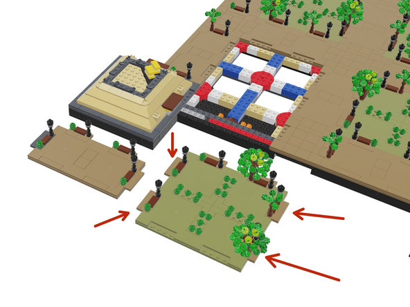
As shown in the illustration for this step, continue by removing the large Panel 1.
-
As shown by the red arrows in the illustration, make sure the four lamp posts and their bases are separated along with Panel 1.
-
-
-
Finish your Section 1 disassembly by removing Panel 1L as shown in the illustration for this step.
-
-
-
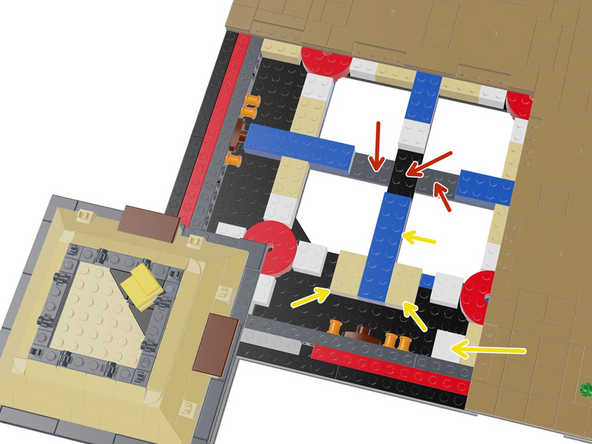
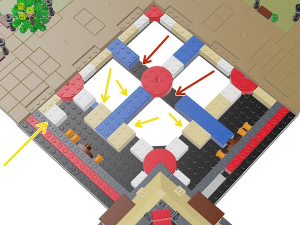
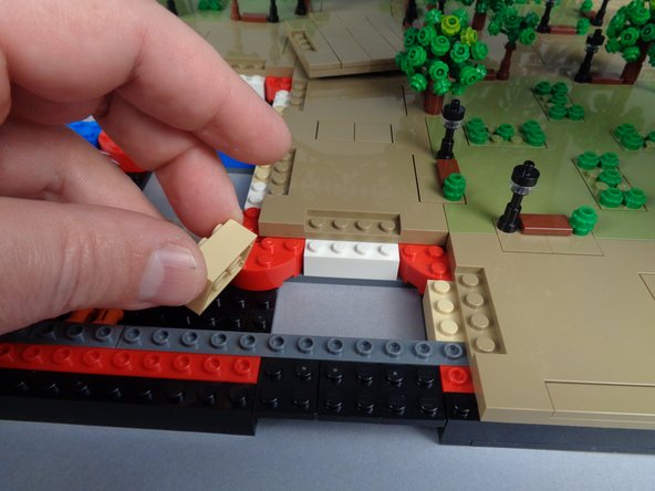
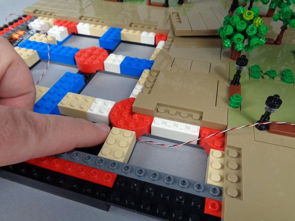
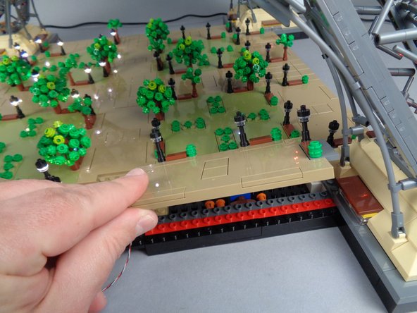
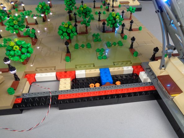
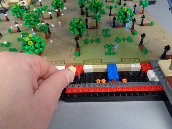
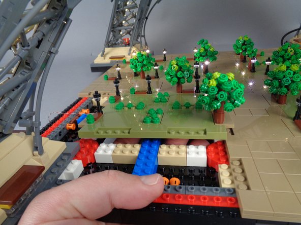
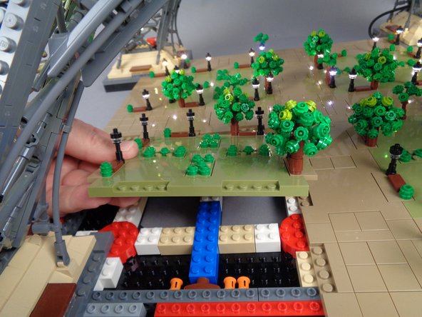
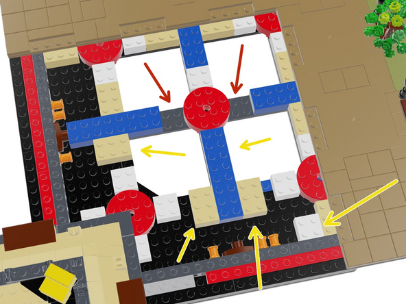
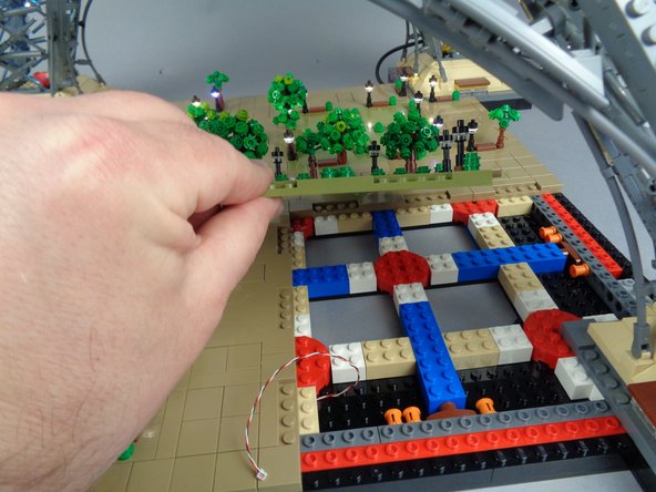
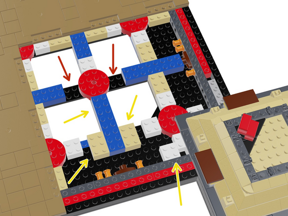
To make room for driver boards and wires in the Section 1 base, you need to re-arrange some bricks in the base as shown in the first illustration for this step.
-
The three red arrows point to where three bricks should be removed. In a later step, you will re-attach these bricks to the bottom of the Section 1 plate you removed earlier.
-
The four yellow arrows in the first illustration point to where bricks will be moved to make room for wires.
-
The two tan 2x3 bricks should be rotated 90 degrees and attached as shown.
-
The white 2x2 brick should be moved from its center position to the position shown.
-
The long blue brick should be moved two studs closer to the center as shown, once the white 2x2 brick has been moved to its new location.
-
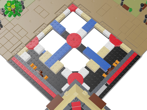
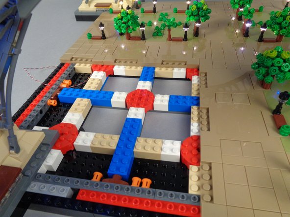
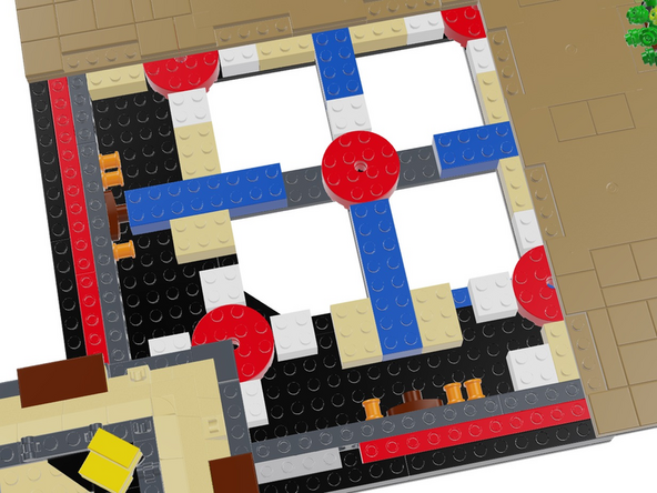
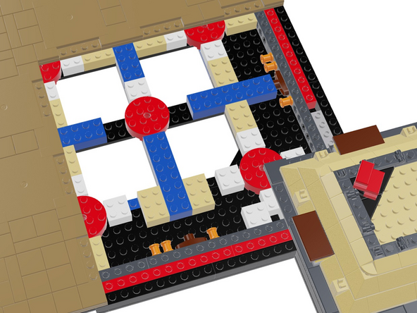
Before proceeding, make sure your bricks are arranged as shown in the second illustration.
-
-
-
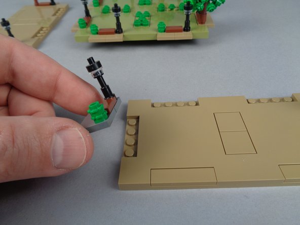
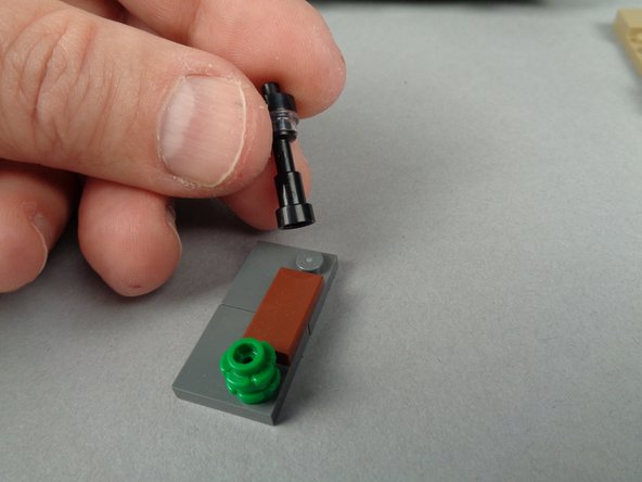
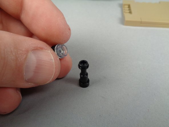
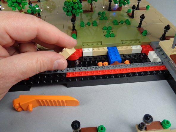
The photos for this step show the steps you will follow to prepare each lamp post before inserting the Microflex LED light.
-
As shown in the first photo, remove the entire 4x2 base section beneath a lamp post.
-
As shown in the second photo, remove the lamp post from its base section.
-
As shown in the third photo, remove the top two pieces from the lamp post.
-
-
-
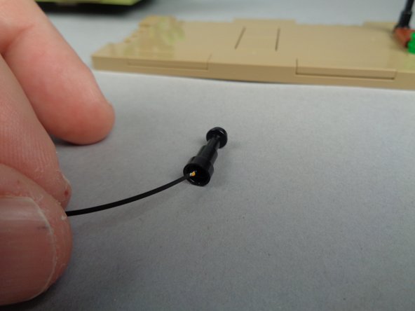
As shown in the two photos for this step, carefully pass the end of the Microflex LED light up through the center of the lamp post until the small LED chip is visible above the top as shown in the second photo.
-
-
-
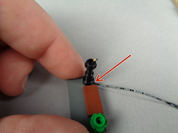
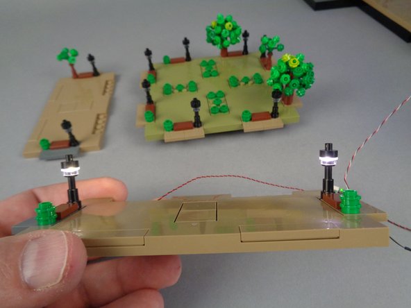
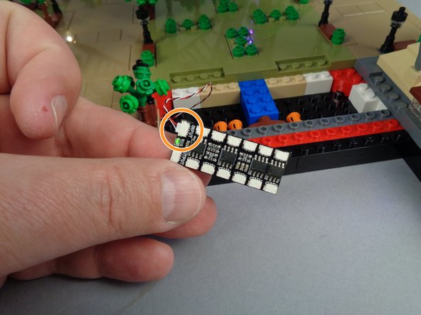
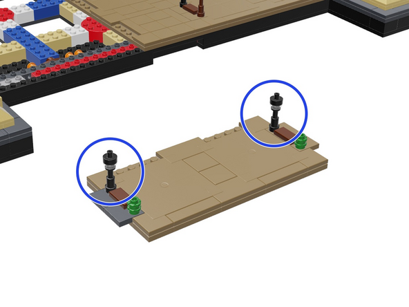
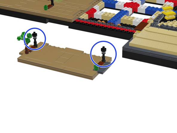
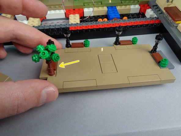
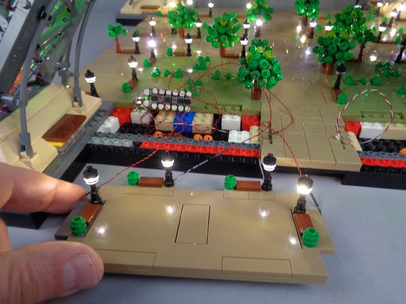
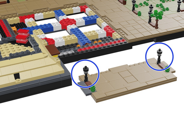
The photos for this step show how to re-attach the lamp post to its base after you have inserted the Microflex LED light.
-
As shown in the first photo, carefully press the lamp post back down on the stud in its original location. The red arrow in the photo shows how the LED wire should be positioned facing the back side of the base section.
-
It is ok to press down on the Microflex LED wire, but make sure the wire is positioned correctly before you fully re-attach the lamp post.
-
As shown by the yellow circle in the second photo for this step, make sure the tiny LED light chip is still visible above the top of the lamp post before pressing down on the lamp post to re-attach it.
-
-
-
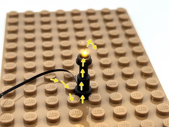
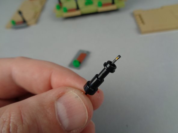
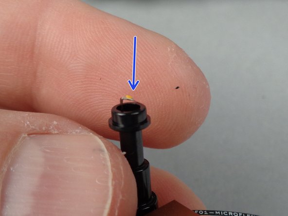
Next you will carefully bend the top of the Microflex LED light so its tiny light chip is facing upward.
-
As shown by the red line in the first photo, carefully bend the LED light below the area of its light chip so the light faces upward.
-
The blue arrow in the second photo shows the light chip facing upward.
-
This process is where the chances are greatest that a Microflex LED light will be damaged, so make sure to bend gently and always below the tiny light chip itself.
-
-
-
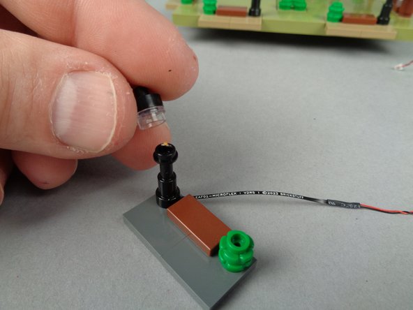
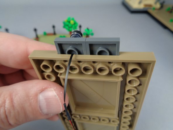
As shown in the first photo for this step, you can re-attach the top pieces of the lamp post.
-
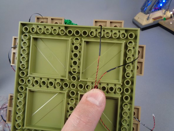
As shown by the yellow box in the second photo for this step, double-check to make sure the wire for the LED light passes out the back of the base section.
-
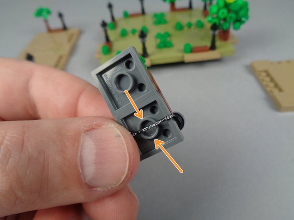
To prepare the base section for re-attachment, bend the LED wire under the base and make sure the wire passes directly OVER the center of the large tube underneath the plate.
-
Making sure the wire is aligned with the center of the tube prevents it from being pinched (and possibly damaged) by the studs underneath when re-attaching.
-
-
-
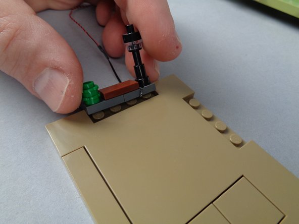
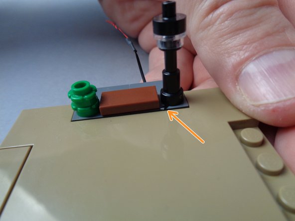
As shown in the first photo for this step, carefully re-attach the lamp post to the base plate.
-
The orange arrow in the second photo shows where the LED light wire passes down and under the plate.
-
As shown in the third photo for this step, the LED light wire passes under the lamp post and down.
-
-
-
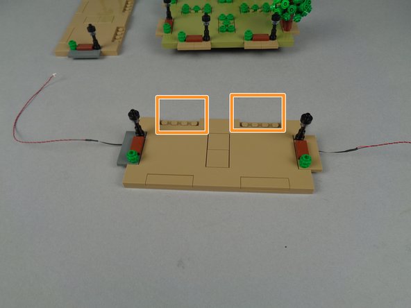
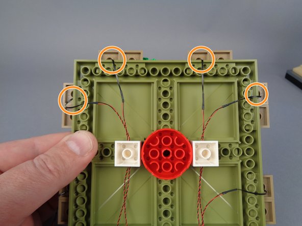
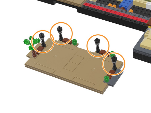
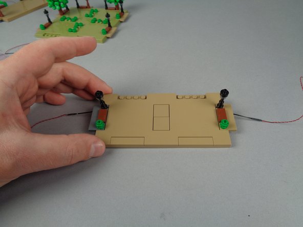
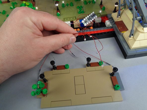
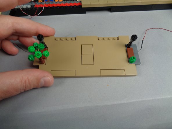
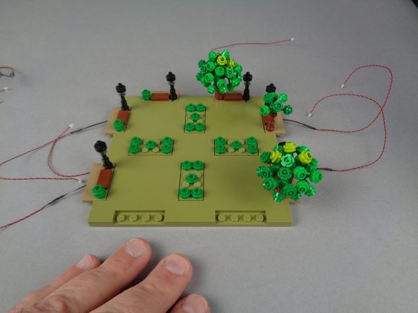
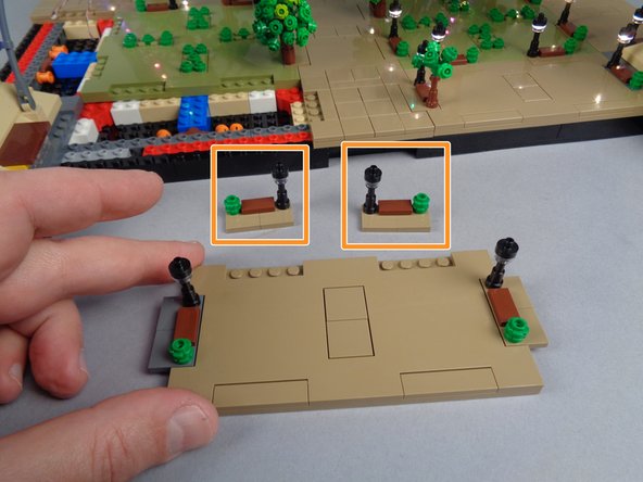
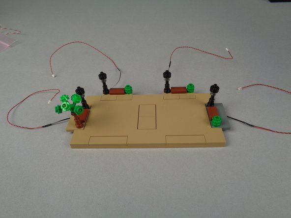
Repeat this process to mount Microflex LED lights inside the four lamp posts on your Panel 1F.
-
Note that the photo for this step only shows two lamp posts (the two missing posts are shown by the two orange rectangles), but you should have all four lamp posts on your panel.
-
-
-
Because the Microflex LED lights can be fragile, we will test the lights in each section before moving to the next panel.
-
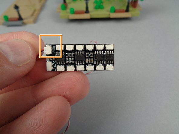
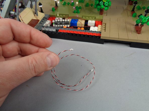
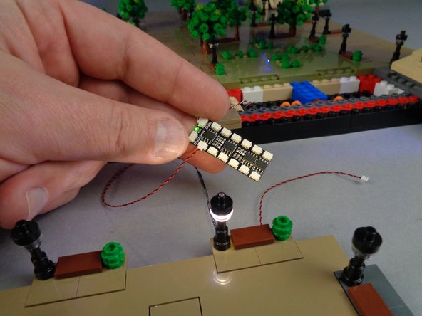
As shown in the first photo for this step, take one of the BRANCH12X driver boards out of its bag, and connect one of the long 3-wire control cables to the INPUT connecting plug on the BRANCH12X driver board.
-
Your add-on kit includes four 3-wire control cables: two long cables (50cm/20" long) and two shorter cables (20cm/8" long).
-
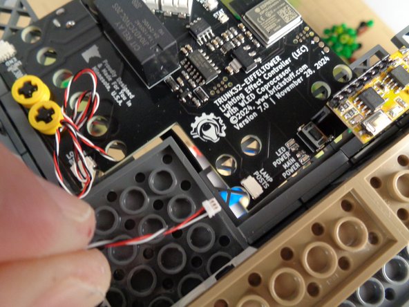
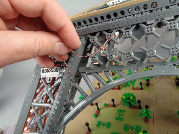
As shown in the second and third photos for this step, connect the other end of the 3-wire control cable to the plug labeled "LAMP POSTS" on your Eiffel Tower's main controller.
-
Don't worry about hiding the wire at this point-- you will route the wire again later and hide it inside the pillar. For now, just connect both ends of the wire as shown.
-
-
-
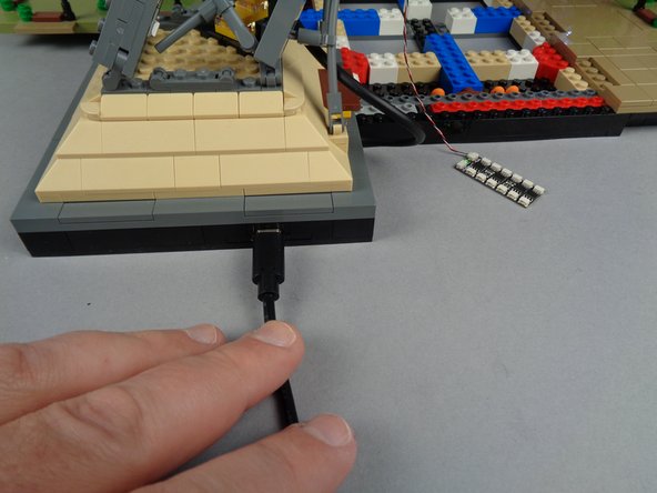
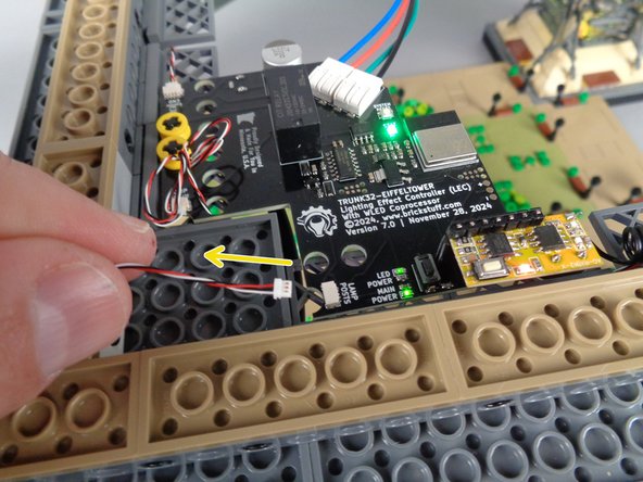
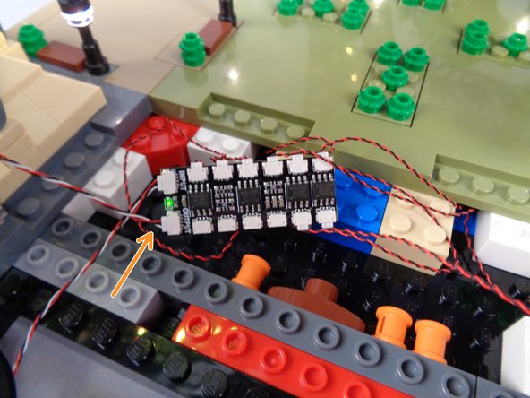
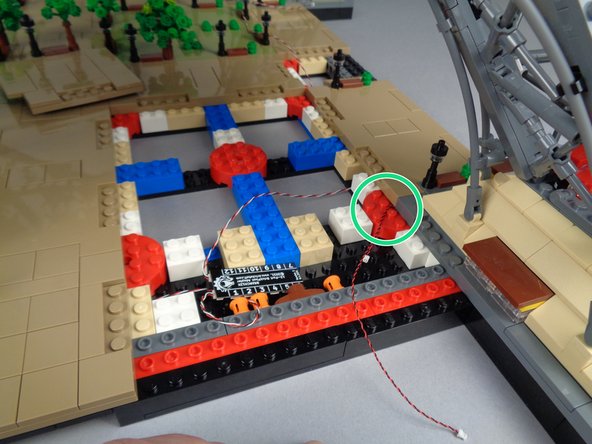
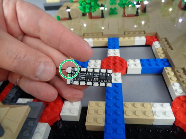
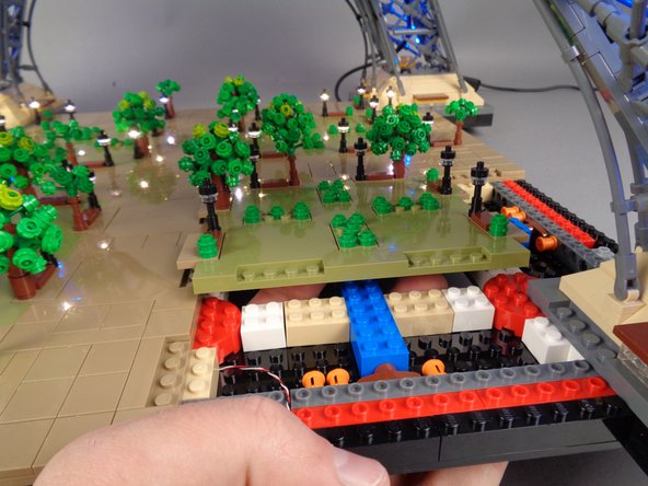
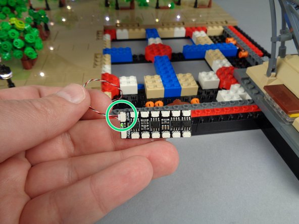
As shown in the first photo for this step, connect your USB-C power cable and make sure the power switch is on.
-
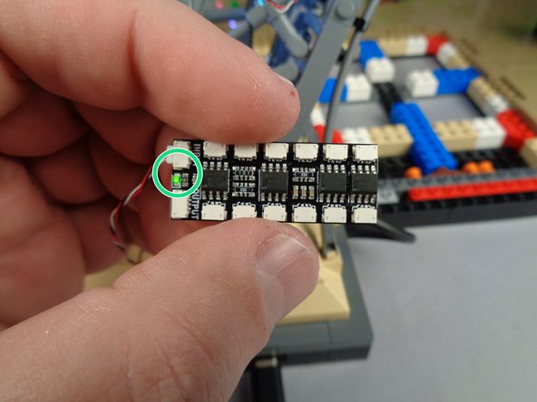
As shown by the green circle in the second photo, you should see the green LED light light up on the BRANCH12X driver board.
-
If you don't see the green LED light turn on, double-check your connections, and make sure the power lights on the main controller are on.
-
-
-
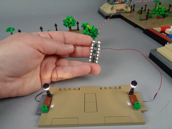
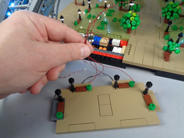
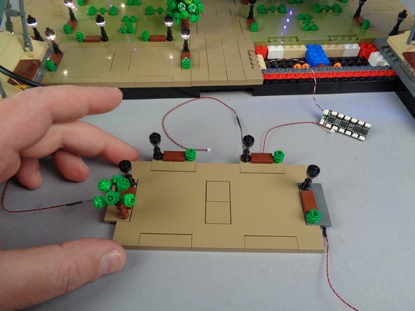
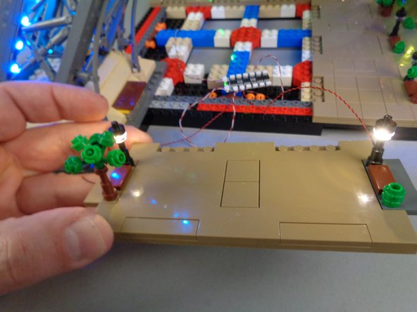
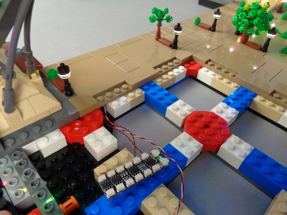
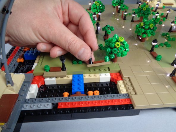
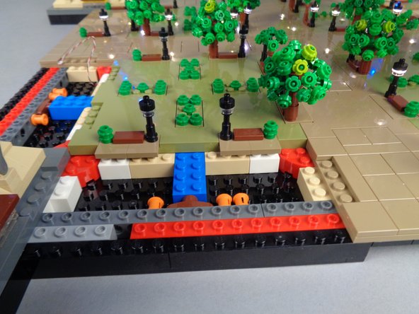
As shown in the photos for this step, connect the lamp post LED light wires to any of the 12 plugs on the BRANCH12X driver board.
-
The specific plug does not matter-- all lamp posts are controlled as a group.
-
The photos for this step show only two lamp posts being connected and tested, but you will have four lamp posts in your Panel 1F section to connect and test.
-
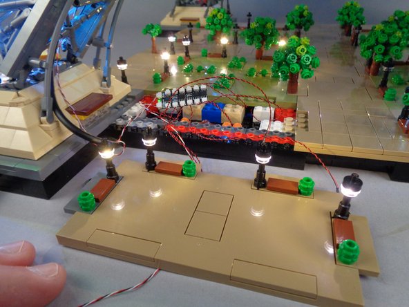
As shown in the second and third photos for this step, you should see all lamp posts turn on and light up.
-
If none of the lamp posts light up but the green LED light on your BRANCH12X driver board is on, try pressing the "C" button on your remote control unit once.
-
If some of the lamp posts light up but not all, double-check the plug connections for the posts that don't light up to make sure the plugs are fully inserted and connected on the BRANCH12X board. If this doesn't fix the issue, you likely have a damaged Microflex LED light and should replace it with one of the spares provided.
-
Once you have verified that both lamp posts are working, you can disconnect them from the BRANCH12X driver board.
-
-
-
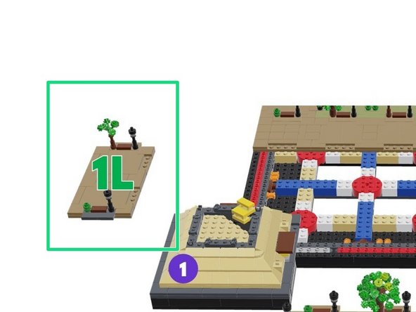
Next you will mount Microflex LED lights in the two lamp posts in Panel 1L. The illustration for this step shows that panel.
-
Follow the same procedures you used for Panel 1F to mount the LED lights inside these lamp posts.
-
-
-
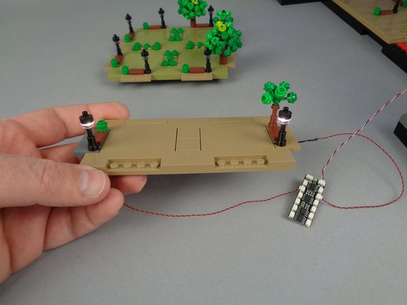
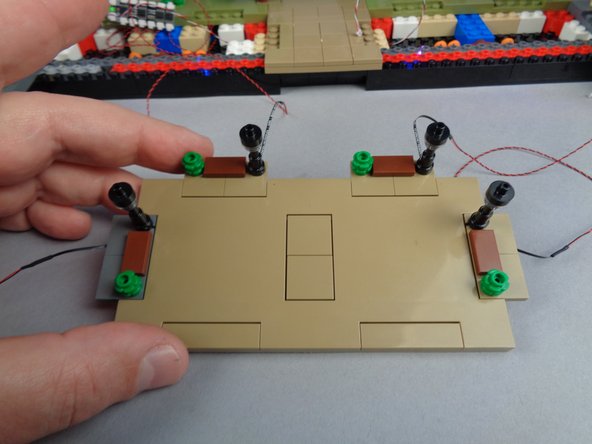
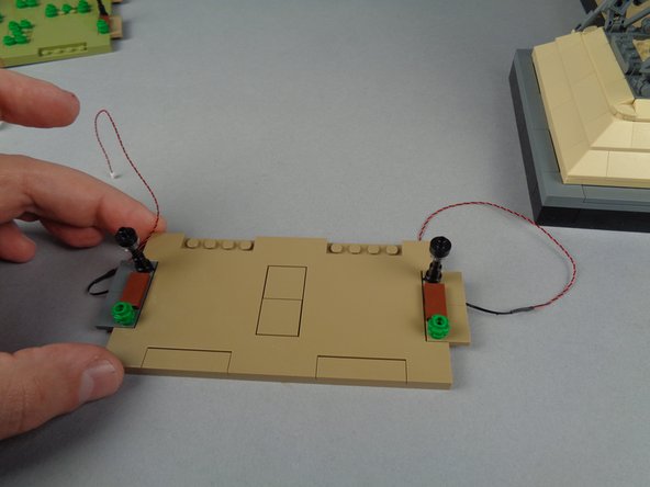
When you are finished mounting the LED lights inside the two lamp posts of Panel 1L, they should look like the setup in the first photo for this step.
-
As shown in the second photo, connect the two lamp posts to any two plugs on the BRANCH12X driver board to make sure they both turn on.
-
If either or both of the lamp posts do not turn on, go back and troubleshoot like you did with the other panel.
-
Once you have verified that all lamp posts on this panel are working, you can disconnect them from the BRANCH12X driver board.
-
-
-
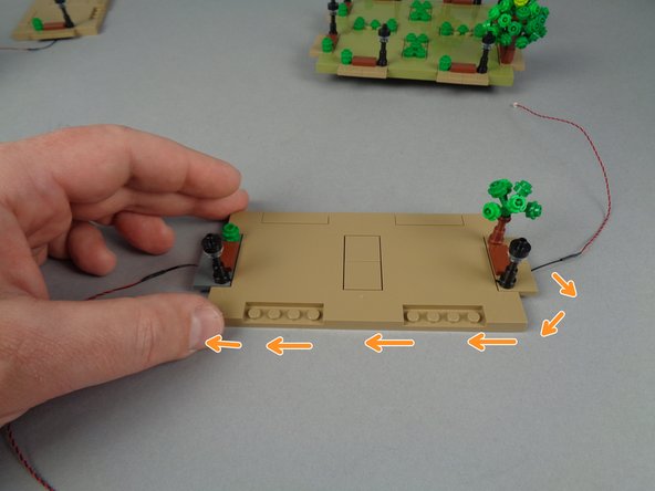
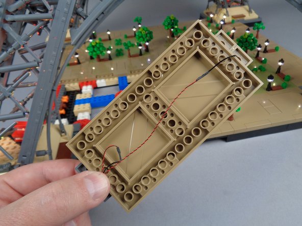
Next you will re-attach Panel 1L to the base of your Eiffel Tower.
-
To prepare, bring the LED Light wire for the lamp post at the top of the panel underneath the panel as shown by the orange arrows in the first photo. See the second photo for what the wire should look like once you have brought it under the panel.
-
-
-
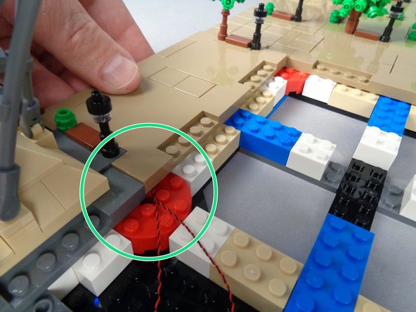
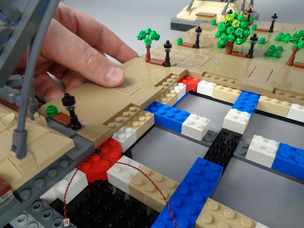
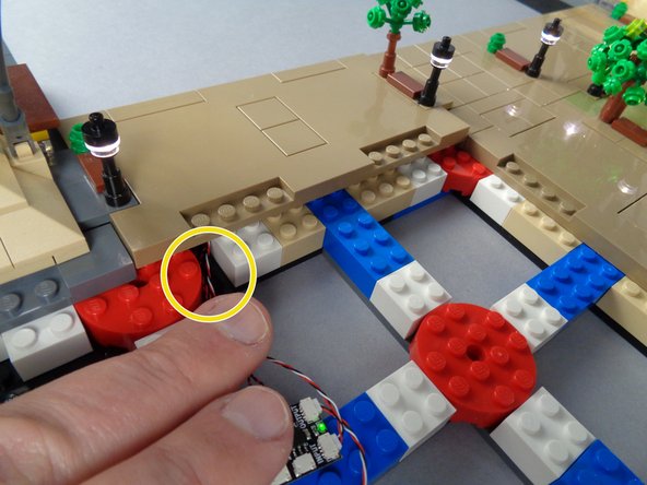
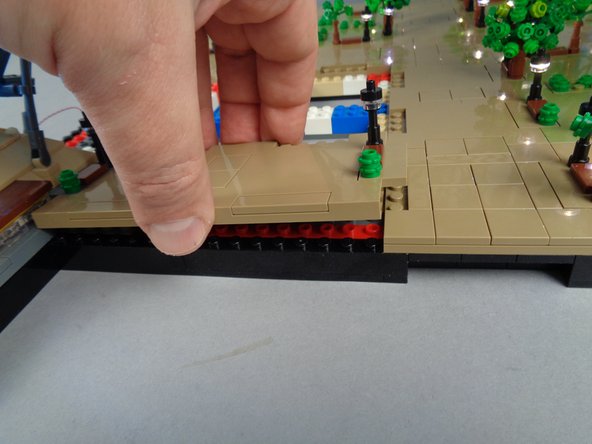
With the LED light wires for both lamp posts passing out of the bottom corner of the panel (as shown by the green circle in the first photo for this step), carefully but firmly press down on Panel 1L to re-attach it.
-
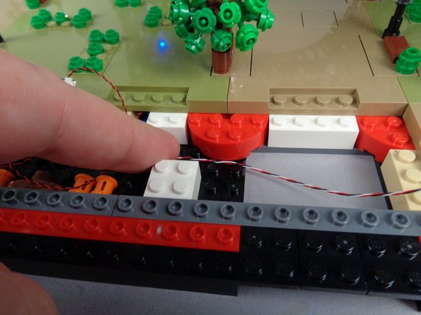
As shown in the third photo for this step, your LED light wires should pass between the studs on top of the red round brick and down into the open area by where your USB-C power wire is located.
-
-
-
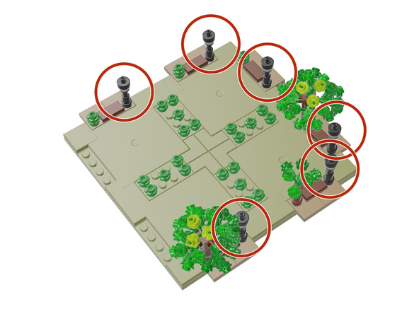
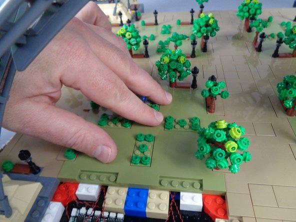
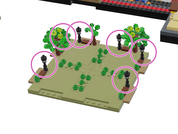
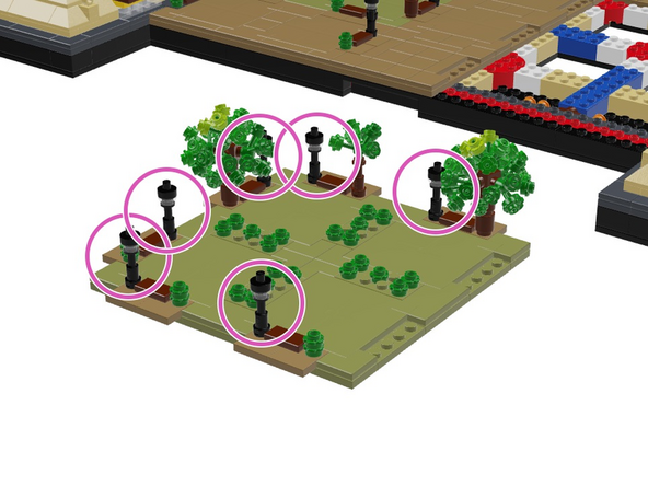
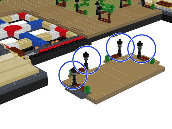
Next you will mount Microflex LED lights into the six lamp posts in the main Panel 1, as shown by the six red circles in the illustration for this step.
-
Follow the same procedures you used for Panel 1F to mount the LED lights inside these lamp posts.
-
-
-
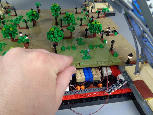
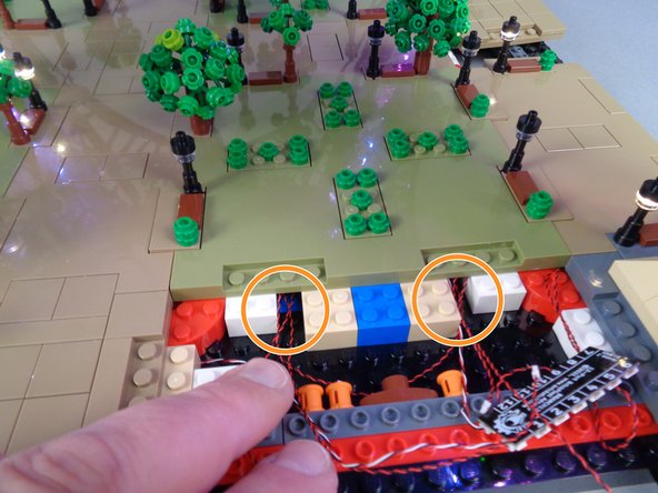
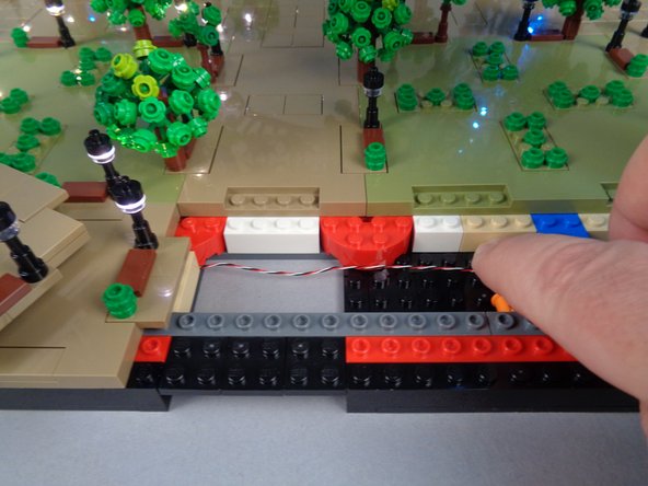
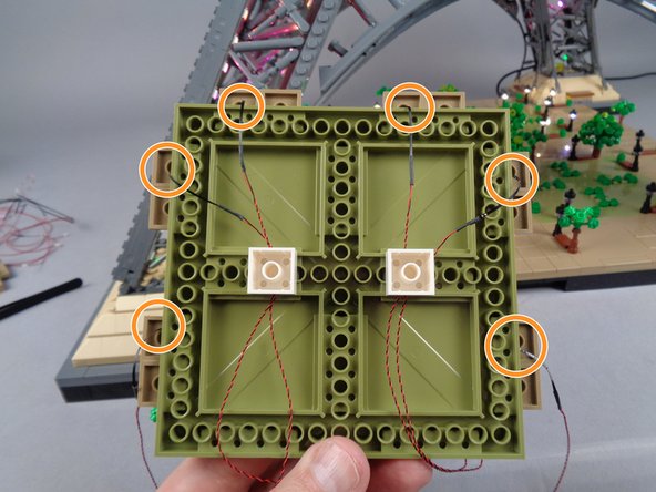
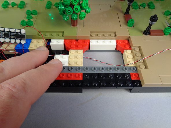
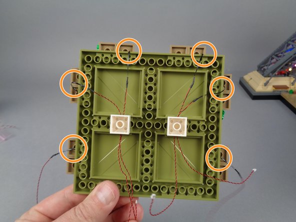
In order to prevent damage to the LED light wires when re-attaching the large plates, you can use the three bricks you removed in Step 12 to hold the wires, as shown in the photo for this step.
-
Note that the wires are passing toward the front of the panel, which is at the bottom of the photo.
-
When using the white 1x2 bricks to hold the LED light wires in place, always leave a little "slack" or extra wire at the edge of the plate-- this is where wires will bend most severely when the plate is re-attached. These areas are shown by the orange circles in the photo.
-
When pressing the white 2x2 bricks on top of the LED light wires, make sure all wires pass between, not on top of, any studs.
-
-
-
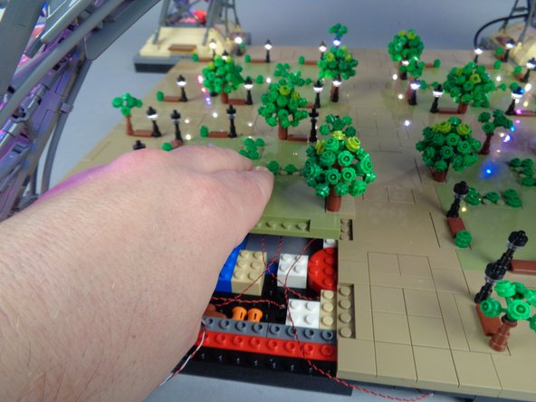
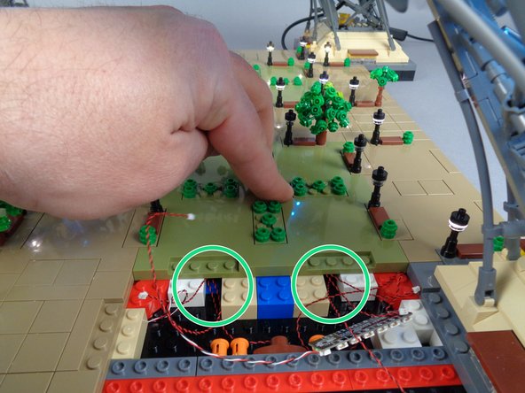
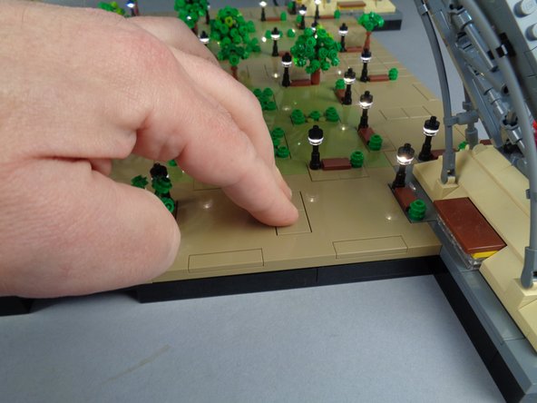
Next, you will re-attach the large Panel 1 section, being careful to make sure all wires are free from pinching and pulling.
-
As shown in the first photo for this step, place Panel 1 back in its original location in the Tower Base.
-
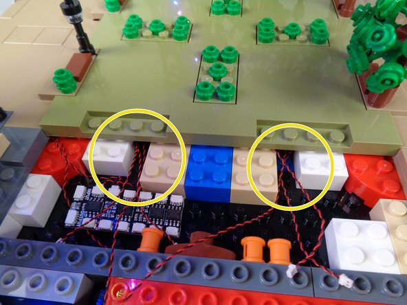
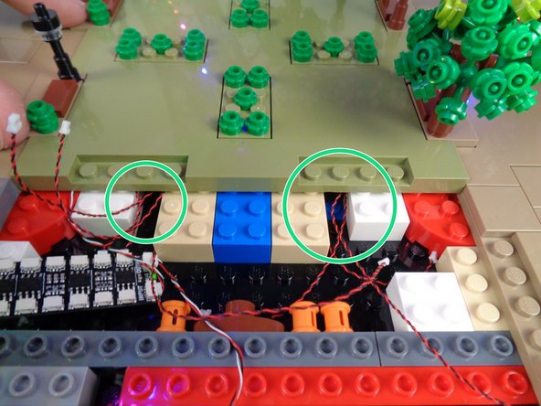
As shown by the two yellow circles in the second photo, before pressing all the way down on the panel to fully re-attach it, make sure the six LED light wires for the Panel 1 lamp posts pass through the gaps between the white and tan bricks.
-
You created these gaps when you re-arranged the base bricks in Step 12.
-
Once you have made sure there are six LED light wires passing through the gaps in the bricks shown in the second photo, you can finish re-attaching Panel 1 by firmly pressing down as shown in the third photo for this step.
-
-
-
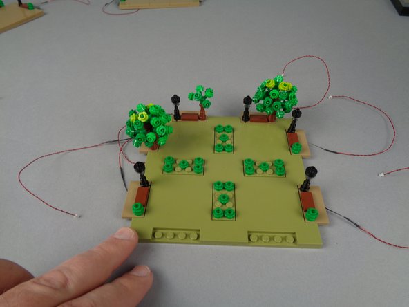
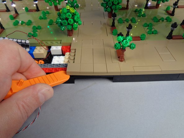
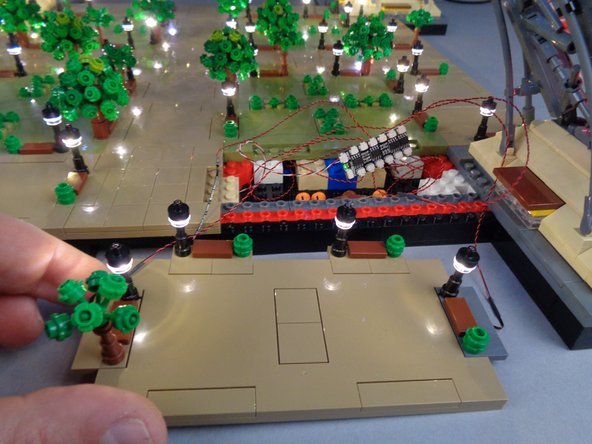
Next, connect the eight lamp posts from Panel 1 and Panel 1L to eight plugs on the BRANCH12X driver board as shown in the first photo for this step.
-
As shown in the second photo for this step, all eight lamp posts should light up.
-
If some or all of the lamp posts do not turn on, go back and troubleshoot like you did when mounting lights inside the lamp posts earlier.
-
Once you have verified that all eight lamp posts work, you can permanently route the BRANCH12X control cable in the next step.
-
-
-
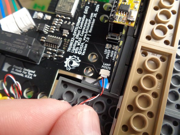
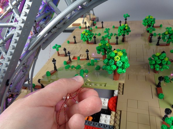
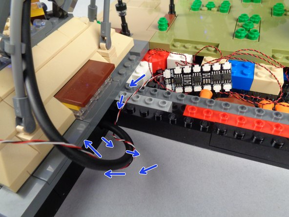
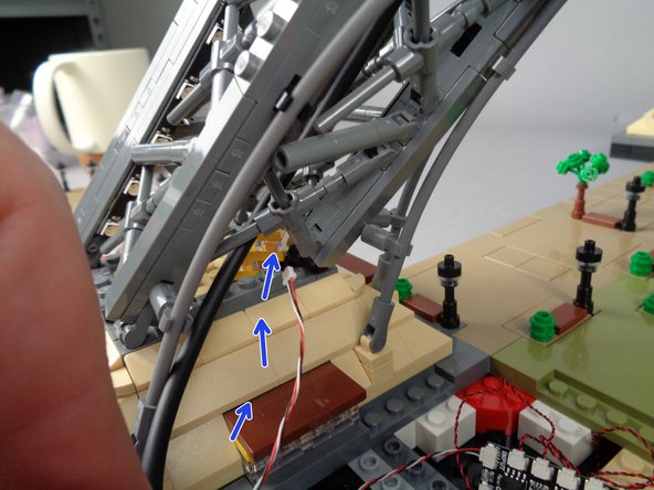
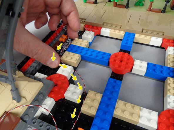
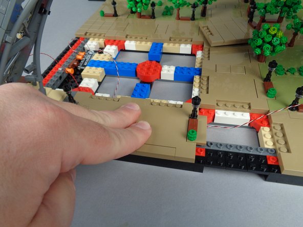
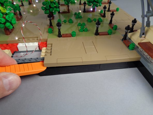
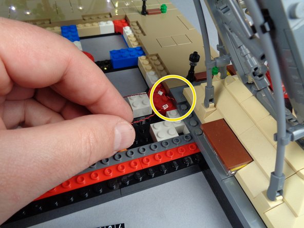
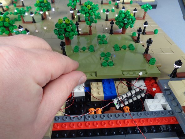
As shown by the yellow arrow in the first photo for this step, carefully disconnect the 3-wire control cable from the "LAMP POSTS" plug on the main controller.
-
Keep your main controller connected to power.
-
As shown by the blue arrows in the second and third photos for this step, wrap the control cable around the USB-C power cable and then up into Pillar 1 of your Eiffel Tower.
-
The control cable will follow the USB-C power cable up the inside of the pillar.
-
-
-
As shown by the first photo for this step, pull the control cable out the top of the pillar.
-
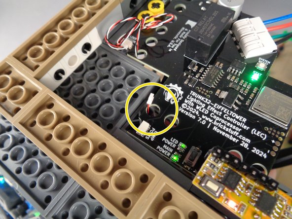
As shown by the yellow circle in the second photo for this step, carefully pass the control cable under the main controller and through the hole in the board next to the "LAMP POSTS" plug.
-
As shown in the third photo for this step, re-connect the control cable to the "LAMP POSTS" plug on the main controller.
-
-
-
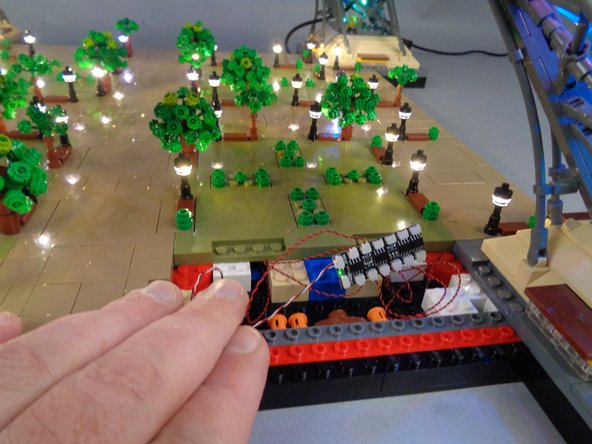
As shown in the photo for this step, verify that all eight lamp posts are on once again after you have re-connected the control cable to the main controller.
-
-
-
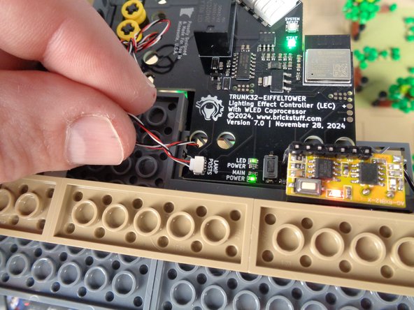
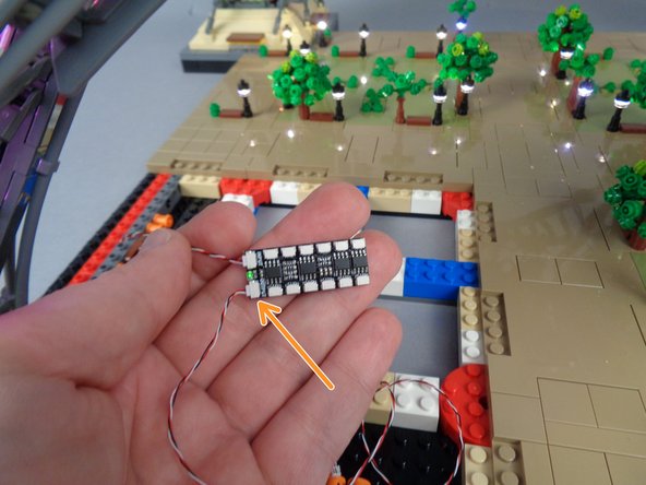
As shown in the first photo for this step, take one of the shorter 3-wire control cables from your kit bag.
-
As shown by the orange arrow in the second photo for this step connect this shorter control cable to the OUTPUT plug on the BRANCH12X driver board.
-
-
-
As shown in the photos for this step, connect the LED light wires from the four lamp posts on Panel 1F to the four remaining open plugs on the BRANCH12X driver board.
-
As shown in the second photo for this step, the four lamp posts should turn on. You should now have all 12 lamp posts in Section 1 turned on.
-
If some or all of the lamp posts do not turn on, go back and troubleshoot like you did when mounting lights inside the lamp posts earlier.
-
-
-
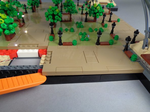
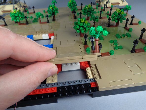
As shown in the photos for this step, next you will remove the panel next to Panel 1F-- this will allow you to pass the control cable from Section 1 to Section 2 which you will work on next.
-
This panel can be difficult to remove, so work slowly, and use your brick separator in several areas if needed to loosen until the panel can be removed.
-
-
-
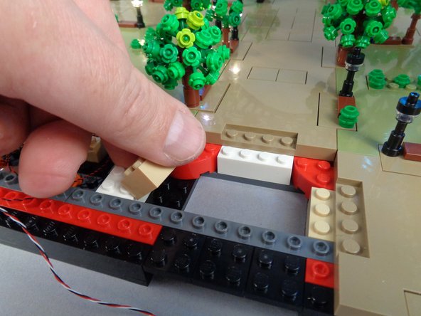
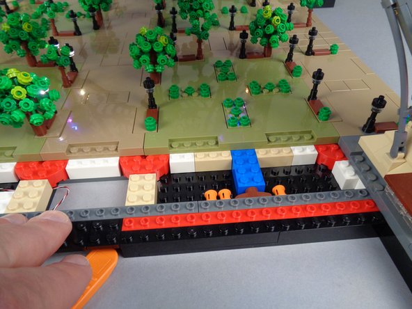
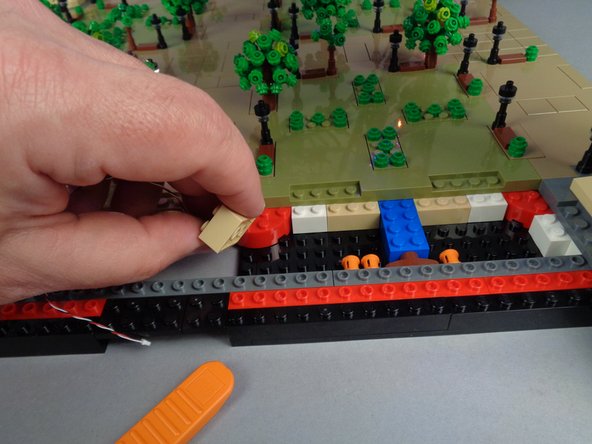
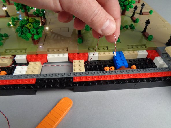
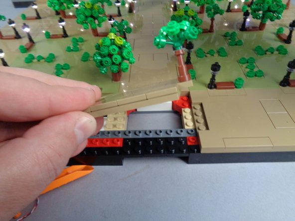
As shown in the photos for this step, temporarily lift the 2x3 tan brick and run the control cable between the studs on the black bottom plate, then re-attach the tan 2x3 brick on top of the control cable.
-
-
-
Next you will remove Panel 2F as shown in the photos for this step. This will allow you to finish running the control cable to where you will work on the next group of lamp posts.
-
-
-
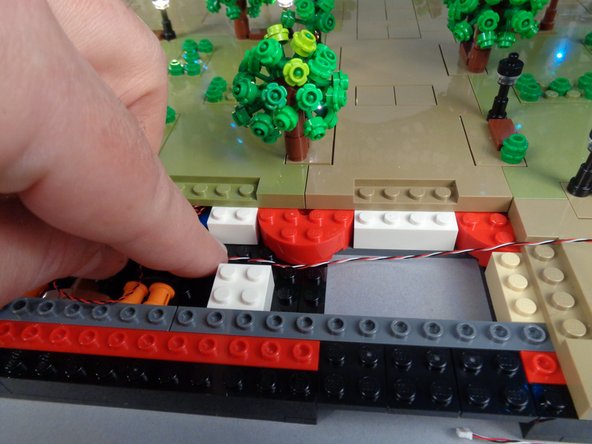
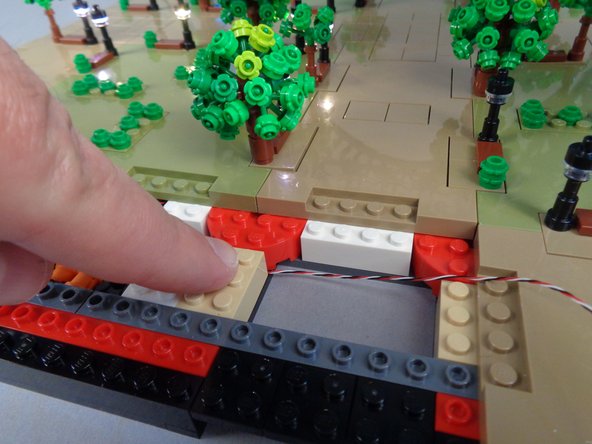
As shown in the photos for this step, remove the 2x3 tan brick under Panel 2F and run the control cable between the studs on the black bottom plate, then re-attach the tan brick on top of the cable.
-
As shown in the third photo, you should now have the control cable passing from Section 1 (the lamp posts you have already connected) over to Section 2 (where you will work next).
-
-
-
As shown in the photos for this step, re-attach the small panel between Sections 1 and 2 that you removed earlier.
-
-
-
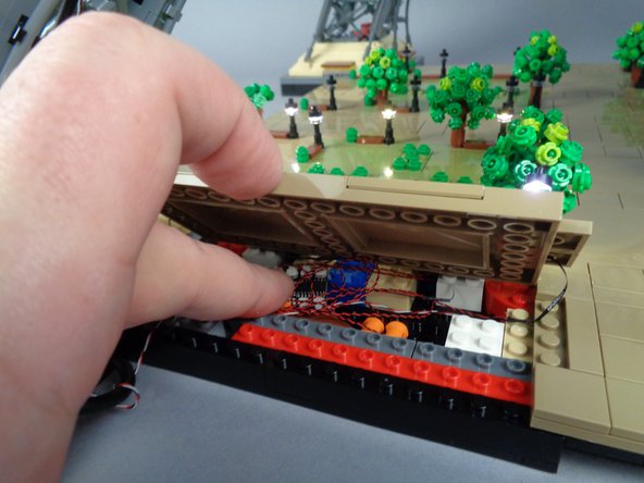
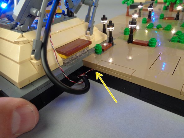
As shown in the first photo for this step, make sure all light wires are gathered underneath Panel 1F, and also that the BRANCH12X driver board is positioned under the panel with enough space that the panel will not crush the driver board when you re-attach it.
-
Once all wires have been collected underneath the panel, carefully re-attach it as shown in the second photo for this step, pressing firmly to re-attach the panel.
-
Work slowly as you re-attach the panel, making sure no LED light wires stick out or get pinched as you press down on the panel. The only visible wire should be the 3-wire control cable that passes up to the main controller.
-
As shown by the yellow arrow in the third photo for this step, the only visible wire coming out of the panel should be the control cable, and this cable should pass between, not on top of, any studs.
-
Once you have re-attached all panels in Section 1, make sure all lamp posts are still lit. If so, you can proceed to mounting LED Lights into the lamp posts in Section 2.
-
-
-
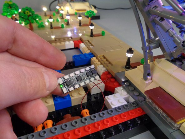
Take another BRANCH12X driver board from your kit bag, and connect the control cable you routed earlier to the INPUT plug on the BRANCH12X as shown in the photo for this step.
-
-
-
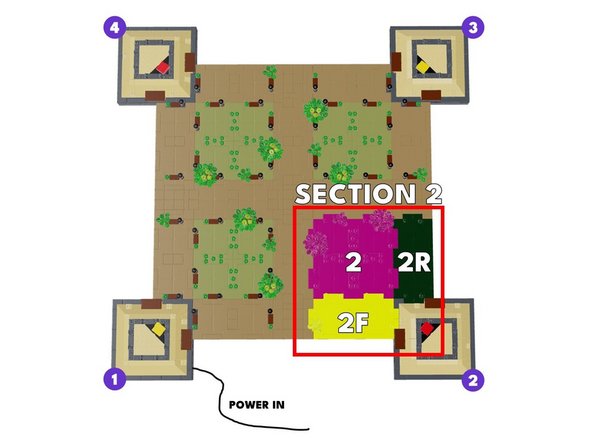
The first illustration for this step shows the three panels you will be working with in Section 2 of your Eiffel Tower base.
-
Note the labels for each panel:
-
Panel 2 is the large center panel.
-
Panel 2F is the panel in the front (facing you), which you have already removed.
-
Panel 2R is the panel at the right-hand side of Section 2.
-
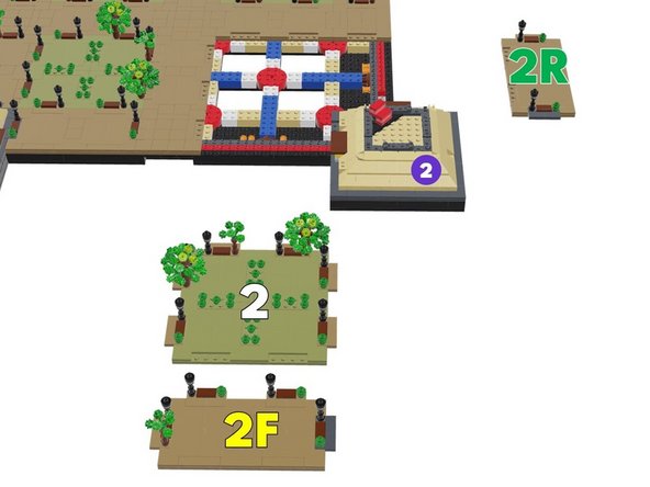
The second illustration for this step shows the three panels in this section after they have been removed. You'll remove Panels 2 and 2R after you install LED lights into the lamp posts in Panel 2F.
-
-
-
As shown by the four orange circles in the illustration for this step, follow the same steps you've used before to mount Microflex LED lights inside the four lamp posts in Panel 2F.
-
When you have mounted the four LED lights, your setup should look like the first photo for this step.
-
As shown in the final photo for this step, connect each of the four lamp posts to the BRANCH12X driver board to make sure each lights up. Troubleshoot as needed if less than four lamp posts light up.
-
-
-
As shown in the photos for this step, remove the large center Panel 2.
-
-
-
As shown in the photos for this step, next you will remove Panel 2R.
-
-
-
To make room for driver boards and wires in the Section 2 base, you need to re-arrange some bricks in the base as shown in the first illustration for this step.
-
The two red arrows point to where two white 2x2 bricks should be removed. In a later step, you will re-attach these bricks to the bottom of the Section 2 plate you removed earlier.
-
The five yellow arrows in the first illustration point to where bricks will be moved to make room for wires.
-
The three tan 2x3 bricks should be rotated 90 degrees and attached as shown.
-
The white 2x2 brick should be moved from its center position to the position shown.
-
The long blue brick should be moved two studs closer to the center as shown, once the white 2x2 brick has been moved to its new location.
-
Before proceeding, make sure your bricks are arranged as shown in the second illustration.
-
-
-
The two blue circles in the illustration for this step show the two lamp posts in Panel 2R. Use the same steps you've used before to mount Microflex LED lights into these lamp posts.
-
When you are finished, your setup should look like the photo.
-
Although not pictured in this step, you should connect each of the lamp posts you just mounted to the BRANCH12X driver board to make sure both lights work.
-
-
-
As shown by the six purple circles in the illustration for this step, next you will mount Microflex LED lights into the six lamp posts in Panel 2.
-
When you are finished, your setup should look like the photo for this step.
-
Although not pictured in this step, you should connect each of the lamp posts you just mounted to the BRANCH12X driver board to make sure all lights work.
-
-
-
In order to prevent damage to the LED light wires when re-attaching the large plates, you can use the two white 2x2 bricks you removed in Step 47 to hold the wires, as shown in the photo for this step.
-
Note that the wires are passing toward the front of the panel, which is at the bottom of the photo.
-
When using the white 1x2 bricks to hold the LED light wires in place, always leave a little "slack" or extra wire at the edge of the plate-- this is where wires will bend most severely when the plate is re-attached. These areas are shown by the orange circles in the second photo.
-
When pressing the white 2x2 bricks on top of the LED light wires, make sure all wires pass between, not on top of, any studs.
-
-
-
Next you will take another 3-wire control cable from your kit bag-- this time you will use the LONG cable as shown in the first photo for this step.
-
You should have one remaining short 3-wire cable in your kit bag. Save this-- you will use it later.
-
As shown by the green arrow in the second photo for this step, connect one end of the control cable to the OUTPUT plug on the BRANCH12X driver board.
-
-
-
Next you will route the long control cable over to the Section 3 panels.
-
As shown by the yellow arrows in the photo, route the control cable through the gaps between the white and tan bricks (you made these gaps when you re-arranged bricks in Step 47).
-
-
-
As shown in the first and second photos for this step, remove the small panel between Sections 2 and 3 (this is the small panel next to Panel 2R).
-
-
-
As shown in the photos for this step, remove the 2x3 tan brick under Panel 2R and run the control cable between the studs on the black bottom plate, then re-attach the tan brick on top of the cable.
-
Make sure the control cable runs between, not on top of, any studs.
-
-
-
Prepare to re-attach Panel 2R by running the lamp post light wire for the far lamp post toward the pillar, as shown by the yellow arrows in the first photo.
-
As shown by the green circle in the second photo for this step, route the two LED Light wires so they pass on top of the round red brick and back toward the BRANCH12X driver board. Make sure wires pass between, not on top of, any studs.
-
As shown in the third photo for this step, press down to firmly re-attach Panel 2R.
-
-
-
As shown in the photo for this step, connect the two lamp posts on Panel 2R to any two plugs on the BRANCH12X driver board. Make sure both lamp posts light up as shown in the photo.
-
-
-
Next you will prepare to re-attach Panel 2.
-
As shown in the first photo for this step, position Panel 2 to be re-attached but do not press down yet.
-
As shown by the orange circles in the second photo for this step, make sure the wires for all six lamp posts on Panel 2 are positioned so they run between the gaps in the white and tan bricks.
-
Once you have made sure no light wires are being pinched, you can press down firmly to re-attach Panel 2.
-
As shown in the third photo for this step, connect the six Panel 2 lamp posts to any available plugs on the BRANCH12X driver board.
-
You should see a total of eight lamp posts lighting up as shown in the third photo: two from Panel 2R and six from Panel 2.
-
-
-
Next you will re-attach Panel 2F.
-
Connect the four lamp posts on Panel 2F to the remaining four plugs on the BRANCH12X driver board as shown in the first photo.
-
As shown in the second photo, all lamp posts in Section 2 should now be lit up. If any lamp posts are not lit, troubleshoot using the procedures described earlier in this guide.
-
Make sure all light wires are gathered underneath Panel 2F, and also that the BRANCH12X driver board is positioned under the panel with enough space that the panel will not crush the driver board when you re-attach it.
-
Once all wires have been collected underneath the panel, carefully re-attach it as shown in the third photo for this step, pressing firmly to re-attach the panel.
-
Work slowly as you re-attach the panel, making sure no LED light wires stick out or get pinched as you press down on the panel.
-
Congratulations! You have installed half of the lights in your add-on kit. Now is a good time to take a break if you have not yet done so.
-
-
-
Prepare to work on the lights in Section 3 by removing Panel 3R as shown in the photos for this step.
-
Panel 3R is the panel directly next to the small panel you removed earlier to run the long control cable.
-
-
-
As shown in the photos for this step, remove the 2x3 tan brick under Panel 3R and run the control cable between the studs on the black bottom plate, then re-attach the tan brick on top of the cable.
-
Make sure the control cable passes between, not on top of, any studs.
-
As shown in the third photo, you should now have the control cable passing from Sections 1 and 2 (the lamp posts you have already connected) over to Section 3 (where you will work next).
-
-
-
Next you will re-attach the small plate between Panels 2R and 3R (this is the plate you removed earlier to run the control cable).
-
As shown by the yellow arrow in the first photo for this step, carefully lift up the edge lamp post on Panel 2R and its base. This is to make room to re-insert the small plate.
-
As shown in the second photo, carefully slide the small plate back into place, passing it underneath the lamp post you loosened.
-
As shown in the third photo for this step, press down on the small plate to re-attach it, and carefully re-attach the lamp post and base you loosened earlier.
-
-
-
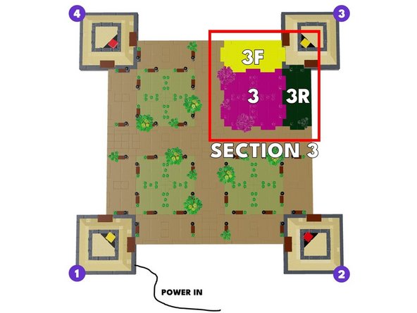
The first illustration for this step shows the three panels you will be working with in Section 3 of your Eiffel Tower base.
-
Note the labels for each panel:
-
Panel 3 is the large center panel.
-
Panel 3F is the panel facing the front.
-
Panel 3R is the panel at the right-hand side of Section 3, which you have already removed.
-
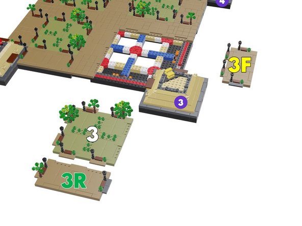
The second illustration for this step shows the three panels in this section after they have been removed. You've already removed Panel 3R. Next you'll remove the other two panels.
-
-
-
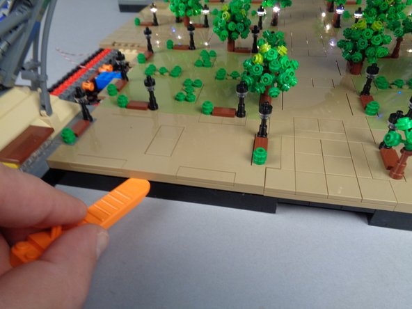
As shown in the three photos for this step, remove Panel 3F.
-
-
-
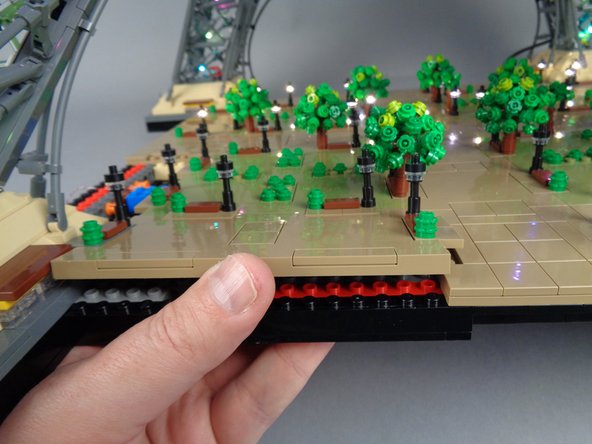
As shown in the three photos for this step, remove the large Panel 3 next.
-
-
-
To make room for driver boards and wires in the Section 3 base, you need to re-arrange some bricks in the base as shown in the first illustration for this step.
-
The two red arrows point to where two white 2x2 bricks should be removed. In a later step, you will re-attach these bricks to the bottom of the Section 3 plate you removed earlier.
-
The five yellow arrows in the first illustration point to where bricks will be moved to make room for wires.
-
The three tan 2x3 bricks should be rotated 90 degrees and attached as shown.
-
The white 2x2 brick should be moved from its center position to the position shown.
-
The long blue brick should be moved two studs closer to the center as shown, once the white 2x2 brick has been moved to its new location.
-
Before proceeding, make sure your bricks are arranged as shown in the second illustration.
-
-
-
As shown by the yellow arrows in the first photo for this step, route the control cable underneath Section 3 and through the gaps between the white and tan bricks.
-
The photos for this step show only some of the bricks re-positioned-- your setup will have more bricks moved than are shown in these photos.
-
As shown by the green circle in the second photo for this step, connect the control cable to the INPUT plug on the BRANCH12X driver board.
-
-
-
As shown in the first photo for this step, take the last control cable in your kit-- this should be a shorter cable than the one you used to connect between Sections 2 and 3.
-
As shown by the orange arrow in the second photo for this step, connect one end of the control cable to the OUTPUT plug on the BRANCH12X driver board.
-
-
-
The two blue circles in the illustration for this step show the two lamp posts in Panel 3R. Use the same steps you've used before to mount Microflex LED lights into these lamp posts.
-
When you are finished, your setup should look like the second photo.
-
Connect the two lamp posts to any two plugs on the BRANCH12X driver board to make sure both light up.
-
You can keep the two lamp posts connected to the BRANCH12X driver board.
-
-
-
As shown in the photos for this step, re-attach Panel 3R to the Eiffel Tower base.
-
While preparing to re-attach the panel, make sure the wires for the two lamp posts pass through the gaps between the bricks under the panel, as shown by the yellow circle in the first photo.
-
Note that the wires in the photo are passing between the gap in the red and white bricks-- your bricks will be arranged slightly differently, and you will have a gap between the white and tan bricks instead.
-
Verify that both lamp posts remain lit when you re-attach Panel 3R.
-
-
-
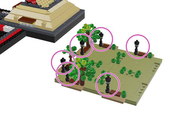
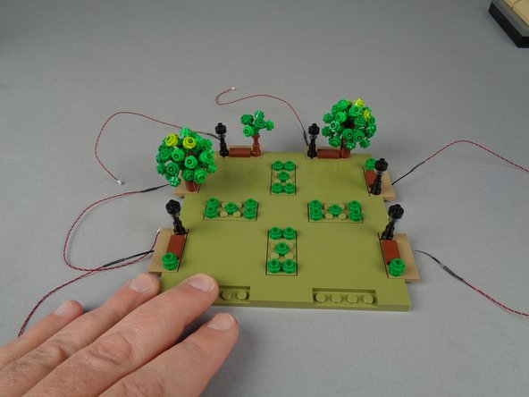
As shown by the six purple circles in the illustration for this step, next you will mount Microflex LED lights into the six lamp posts in Panel 3.
-
When you are finished, your setup should look like the photo for this step.
-
-
-
In order to prevent damage to the LED light wires when re-attaching the large plates, you can use the two white 2x2 bricks you removed in Step 65 to hold the wires, as shown in the photos for this step.
-
Note that the wires are passing toward the front of the panel, which is at the bottom of the photo.
-
When using the white 1x2 bricks to hold the LED light wires in place, always leave a little "slack" or extra wire at the edge of the plate-- this is where wires will bend most severely when the plate is re-attached. These areas are shown by the orange circles in the second photo.
-
When pressing the white 2x2 bricks on top of the LED light wires, make sure all wires pass between, not on top of, any studs.
-
-
-
Next you will prepare to re-attach Panel 3.
-
As shown in the first photo for this step, position Panel 3 to be re-attached but do not press down yet.
-
As shown by the green circles in the second photo for this step, make sure the wires for all six lamp posts on Panel 3 are positioned so they run between the gaps in the white and tan bricks.
-
Once you have made sure no light wires are being pinched, you can press down firmly to re-attach Panel 3.
-
-
-
Next you will route the control cable connected to the OUTPUT plug on the BRANCH12X driver board (green arrow in the first photo) so it runs toward Section 4 where you will mount the final set of lamp posts.
-
As shown in the second and third photos for this step, remove the small panel between Panel 3F and Panel 4F.
-
-
-
As shown in the photos for this step, remove the 2x3 tan brick under Panel 3F and run the control cable between the studs on the black bottom plate, then re-attach the tan brick on top of the cable.
-
Make sure the control cable runs between, not on top of, any studs.
-
-
-
As shown in the first photo for this step, remove Panel 4F.
-
As shown in the second and third photos for this step, remove the 2x3 tan brick under Panel 4F and run the control cable between the studs on the black bottom plate, then re-attach the tan brick on top of the cable.
-
Make sure the control cable runs between, not on top of, any studs.
-
-
-
Next you will re-attach the small plate you removed to make space to route the control cable.
-
If one of the lamp posts from Panel 4F is attached to the small plate (as shown by the blue arrow in the first photo), remove it and attach it instead to Panel 4F as shown by the yellow arrow and also in the second photo.
-
Re-attach the small plate you removed earlier, as shown in the third photo for this step.
-
-
-
Moving back to Panel 3F, use the same steps you've used before to mount Microflex LED lights into the four lamp posts on this panel (shown by the four blue circles in the first illustration).
-
When you are finished, your setup should look like the first photo in this step.
-
As shown in the second photo for this step, connect the four lamp posts to the final four open plugs on the BRANCH12X driver board, and verify that all lamp posts in Section 3 are working.
-
-
-
As you have done with the previous two sections, you will now close up the last panel in Section 3.
-
Make sure all light wires are gathered underneath Panel 3F, and also that the BRANCH12X driver board is positioned under the panel with enough space that the panel will not crush the driver board when you re-attach it.
-
Once all wires have been collected underneath the panel, carefully re-attach it as shown in the first photo for this step, pressing firmly to re-attach the panel.
-
Work slowly as you re-attach the panel, making sure no LED light wires stick out or get pinched as you press down on the panel.
-
When you are finished re-attaching the panel, all lights in your setup should be lit, as shown in the second photo for this step.
-
There should be a total of 36 lamp posts lit so far. You will connect the remaining 12 lamp posts in the following steps.
-
-
-
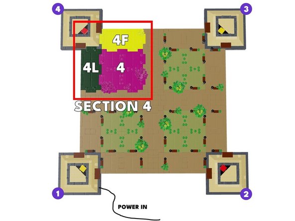
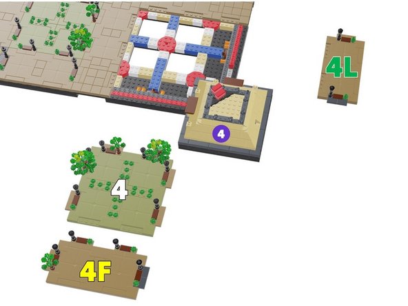
The first illustration for this step shows the three panels you will be working with in Section 4 of your Eiffel Tower base.
-
Note the labels for each panel:
-
Panel 4 is the large center panel.
-
Panel 4F is the panel facing the front, which you have already removed.
-
Panel 4L is the panel at the left-hand side of Section 4.
-
The second illustration for this step shows the three panels in this section after they have been removed. You've already removed Panel 4F. Next you'll remove the other two panels.
-
-
-
As shown in the photos for this step, remove Panel 4L.
-
-
-
If the two lamp posts shown by the orange boxes in the first photo for this step separated along with Panel 4L, you will need to re-position them onto the large center Panel 4 as shown in the second and third photos.
-
-
-
As shown in the photos for this step, remove the large center Panel 4.
-
-
-
To make room for driver boards and wires in the Section 4 base, you need to re-arrange some bricks in the base as shown in the first illustration for this step.
-
The two red arrows point to where two white 2x2 bricks should be removed. In a later step, you will re-attach these bricks to the bottom of the Section 4 plate you removed earlier.
-
The four yellow arrows in the first illustration point to where bricks will be moved to make room for wires.
-
The two tan 2x3 bricks should be rotated 90 degrees and attached as shown.
-
The white 2x2 brick should be moved from its center position to the position shown.
-
The long blue brick should be moved two studs closer to the center as shown, once the white 2x2 brick has been moved to its new location.
-
Before proceeding, make sure your bricks are arranged as shown in the second illustration.
-
-
-
Take the fourth and final BRANCH12X driver board from its kit bag, and connect the end of the control cable to the INPUT plug on the BRANCH12X.
-
You will leave the OUTPUT plug unconnected (open) and will not connect anything here.
-
-
-
The two blue circles in the illustration for this step show the two lamp posts in Panel 4L. Use the same steps you've used before to mount Microflex LED lights into these lamp posts.
-
When you are finished, your setup should look like the second photo.
-
-
-
As shown in the first photo for this step, run the wire for the far lamp post under the bottom of Panel 4L.
-
As shown in the second photo for this step, carefully re-position Panel 4L with the light wires running toward the BRANCH12X driver board.
-
As shown by the yellow circle in the third photo for this step, make sure the light wires pass over the top of the round red brick, and that the wires pass between, not on top of, any studs.
-
Make sure both light wires can reach the BRANCH12X driver board.
-
Once you have verified the wires can reach, you can press firmly down on Panel 4L to re-attach it to your Tower base.
-
-
-
As shown in the photo for this step, connect the two lamp posts on Panel 4L to any two plugs on the BRANCH12X driver board, and verify that both lamp posts light up.
-
-
-
As shown by the six purple circles in the illustration for this step, next you will mount Microflex LED lights into the six lamp posts in Panel 4.
-
When you are finished, your setup should look like the photo for this step.
-
-
-
In order to prevent damage to the LED light wires when re-attaching the large plates, you can use the two white 2x2 bricks you removed in Step 83 to hold the wires, as shown in the photo for this step.
-
Note that the wires are passing toward the front of the panel, which is at the bottom of the photo.
-
When using the white 1x2 bricks to hold the LED light wires in place, always leave a little "slack" or extra wire at the edge of the plate-- this is where wires will bend most severely when the plate is re-attached. These areas are shown by the orange circles in the photo.
-
When pressing the white 2x2 bricks on top of the LED light wires, make sure all wires pass between, not on top of, any studs.
-
-
-
Next you will prepare to re-attach Panel 4.
-
As shown in the first photo for this step, position Panel 4 to be re-attached but do not press down yet.
-
As shown by the green circles in the second photo for this step, make sure the wires for all six lamp posts on Panel 4 are positioned so they run between the gaps in the white and tan bricks.
-
Once you have made sure no light wires are being pinched, you can press down firmly to re-attach Panel 4.
-
-
-
As shown in the photo for this step, next you can connect the six lamp posts on Panel 4 to any six plugs on the BRANCH12X driver board.
-
Make sure all six lamp posts on Panel 4 light up.
-
-
-
Now it is time to mount lights in the final four lamp posts!
-
Use the same steps you've used before to mount Microflex LED lights into the four lamp posts on Panel 4F (shown by the four blue circles in the illustration for this step).
-
When you are finished, your setup should look like the photo in this step.
-
-
-
As shown in the photo for this step, connect the four lamp posts on Panel 4F to the last four available plugs on the BRANCH12X driver board.
-
Make sure all four lamp posts light up.
-
-
-
As you have done with the previous three sections, you will now close up the last panel in Section 4.
-
Make sure all light wires are gathered underneath Panel 4F, and also that the BRANCH12X driver board is positioned under the panel with enough space that the panel will not crush the driver board when you re-attach it.
-
Once all wires have been collected underneath the panel, carefully re-attach it as shown in the photo for this step, pressing firmly to re-attach the panel.
-
Work slowly as you re-attach the panel, making sure no LED light wires stick out or get pinched as you press down on the panel.
-
-
-
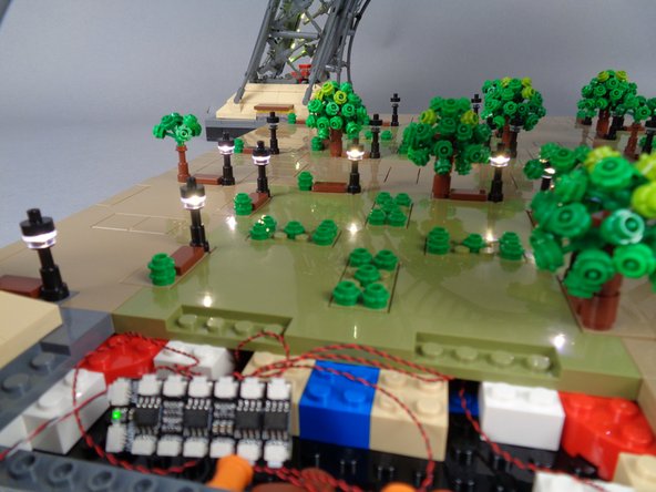
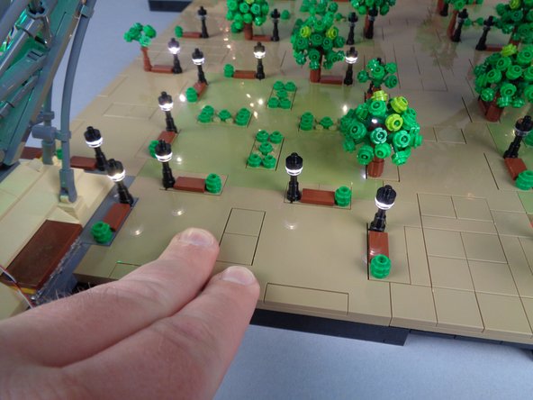
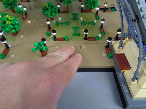
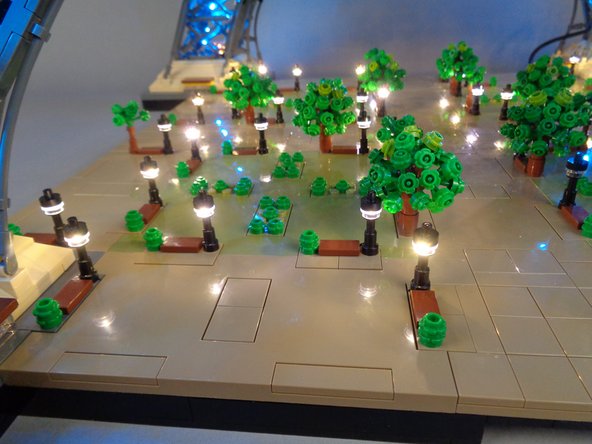
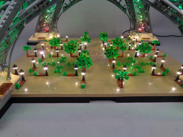
You should now be able to see and enjoy all 48 lamp posts connected and turned on, as shown in the photo for this step.
-
You can find out how to control and customize your lights by reading our Control Guide.
-
If you have any trouble with any lights in your setup:
-
Go back and review the suggested troubleshooting steps listed earlier in this guide.
-
If more than two Microflex lights have been damaged during installation, you can purchase additional lights in packs of four from our website.
-
Make sure you are using the USB-C power supply provided with your Brickstuff kit. We cannot provide support for your kit if you are using another power supply.
-
If you continue to have trouble, contact us at support(at)brickstuff.com and we'll do whatever we can to get you up and running.
-
THANK YOU from all of us at Brickstuff for your support of our work. We hope you enjoy your Eiffel Tower lights for many years to come!
-