
Introduction
Installation instructions for the Brickstuff Premium light and sound kit for the LEGO CREATOR Ecto-1 (#10274). This guide does NOT cover the smaller Ecto-1 (#21108) released through the LEGO Ideas platform in 2014.
Tools
Parts
Featured Document
-
-
There are several ways to read this guide:
-
Reading it on the web in your browser.
-
Downloading a PDF copy of the guide. You can do this by selecting "Download PDF" as shown by the red rectangle in the first photo. Click on the Options heading in the upper right corner of the screen (see the green rectangle).
-
In the "Dozuki" application, which is available for download from the Apple App Store and various Android and Google marketplaces.
-
If you view this guide in the Dozuki app, search for "Brickstuff" the first time you open the app, then select "Product Guides" from the categories listed under Brickstuff. Scroll down to find this guide.
-
You can also translate this guide into another language when viewing on the web. To do this, install a translator extension into your browser and use that extension/plug-in to translate the page. Using the main Google translate website (translate.google.com) does not work.
-
-
-
You will begin installing your Brickstuff kit in the roof section of your Ecto-1.
-
The roof section is fragile, and is built in two parts. When removing the roof, work slowly, keep your LEGO instruction book handy, and be prepared for parts to come loose. These can easily be re-attached after installing the roof lights.
-
As shown in the first photo for this step, place your Ecto-1 on a flat surface with plenty of working room around it. Begin by detaching the hoses and tubes as shown by the red circles.
-
As shown by the orange rectangle in the second photo, carefully detach the black ladder on the side of the vehicle.
-
As shown by the purple circle and arrow in the third photo, carefully detach the two blue hoses by removing the black Technic axle and pin connector from the black Technic pin on the roof.
-
-
-
As shown in the first and second photos, next you will carefully remove the front and rear lightbars.
-
As shown in the third photo, remove the large strobe/steering brick along with its axle.
-
-
-
As shown in the first photo, carefully remove the roof radar dish, making sure to also remove the black Technic connector and red Technic axle connected to the radar dish.
-
As shown in the second photo, remove the radome assembly, including the mounting pillar and small antennas.
-
The roof of your Ecto-1 is now ready to be removed.
-
-
-
Remember, the Ecto-1 roof was not built to be removed easily, so take your time and remember: parts will fall off, but they can be re-attached later.
-
Because the roof of the Ecto-1 is built in two sections, you will remove it in two sections, beginning with the rear section.
-
As shown in the first photo, open the side doors to allow better access to the underside of the roof.
-
Make sure all hoses, ladders, and tubes have been disconnected from the roof before trying to remove it.
-
As shown in the second photo, begin loosening the rear roof section by placing your fingers inside the car, under the flat plates that form the bottom of the roof. Press up gently several times to begin loosening the roof.
-
As shown in the third photo, open the rear door, place your fingers inside and beneath the flat roof section, and gently pressing upward.
-
-
-
As shown by the two green circles in the first photo, it can help to loosen the roof if you press up on the two black arches that anchor the roof to the car body.
-
As shown in the second photo, you can use the brick separator that came with your LEGO set to loosen the sides of the rear roof section.
-
Try to keep the windows attached to the main body of the car, so they do not detach with the roof.
-
As shown in the third photo, you should now have loosened the rear roof section enough so you can slowly but firmly grip it and lift it off.
-
Several white slope pieces will become detached from the front center of the roof-- this is ok. Keep track of them and set them aside.
-
-
-
As shown in the photo for this step, the rear roof section will not separate without several white slopes detaching. That is ok.
-
-
-
The front roof section is easier to remove than the back section.
-
As shown by the green arrows in the first photo, you can use your brick separator to gently pry the white slopes free of the top of the front windshield, which will make removing the front roof section easier.
-
The second photo shows the front roof section being removed after loosening the studs on the top center of the windshield.
-
The third photo shows the two removed roof sections, along with the extra white pieces that will come detached when the roof is removed.
-
You are now ready to begin installing the roof lights.
-
-
-
As shown in the first photo, find the large pink bag labeled "Roof Parts" in your Brickstuff kit.
-
As shown in the second photo, open the large bag and find inside a smaller bag labeled "Blue Roof Lights." This is the bag you will be using first.
-
As shown by the two lines in the third photo, the lights in the "Blue Roof Lights" bag have two different lengths of wire. In the photo, the red line shows the shorter wires while the blue line shows the longer wires.
-
In the next steps, you will first use the two lights with longer wires.
-
-
-
Take the front roof section, and as shown in the first photo for this step, remove the large white plate as well as the light bluish gray plate and the first blue light assembly.
-
As shown by the orange arrows in the first photo, separate the top of the light from the dark bluish gray plate that it attaches to.
-
The green line in the second photo shows the path the light wires will take once the light has been mounted and re-attached.
-
Continue preparing the light by removing the back dome as shown in the third photo.
-
-
-
As shown in the first photo for this step, continue disassembling the first blue light by separating the 1x2 light bluish gray plate with clip.
-
As shown in the second photo for this step, carefully place one of the blue LED lights with longer wires on the 1x2 plate, on the side opposite the studs.
-
As shown by the blue line in the second photo, make sure the LED light is positioned in the center of the plate, and that the LED itself (the small white rectangle) sticks up a small amount beyond the plate. Hold the LED in place with your finger.
-
As shown in the second photo, the top side of the LED light should be facing you. This is the side of the LED without the wires attached.
-
Once you have centered the white rectangle of the LED, carefully re-attach the transparent blue round boat stud you detached earlier.
-
As shown by the red and green circles in the third photo, the LED light should be in the center of the boat stud (green circle), and its wires should not be touching any of the four studs underneath the boat stud (red circles).
-
-
-
As shown in the first photo for this step, re-attach the dome to the back side of the blue light.
-
As shown by the red arrows in the second photo, pass the LED light wire through the center of the clip below the light.
-
it is important to make sure the wire passes between the two clip pieces so it does not get caught or pinched.
-
Finally, as shown in the third photo, re-attach the dark bluish gray plate to the bottom of the light via the clip.
-
As shown by the green arrow in the third photo, the LED light wire must pass through the center and not be caught or pinched by any part of the clip.
-
-
-
As shown in the first photo for this step, re-attach the first blue light to the front roof section.
-
As shown by the orange arrows in the first photo, make sure the LED light wire runs to the side of the studs behind the light. Wires must never run on top of any studs, or they can get pinched or broken when parts are attached on top of them.
-
As shown by the green arrow in the second photo, re-attach the light bluish gray plate behind the blue light, again being careful to make sure the LED light wire runs to the side of the plate.
-
Finally, re-attach the large white plate on top as shown by the purple arrows in the third photo.
-
The green circle shows how the LED light wire should pass through the open channel underneath the white plate and not be pinched or caught on top of any studs.
-
-
-
Follow the same steps you just completed to mount the blue LED light with longer wires in the first blue roof light, and mount a second blue LED light with longer wires inside the second roof light as shown in the photos for this step.
-
As shown by the orange circles in the second photo, both LED light wires should pass under the large white plates inside the hollow channel underneath the plate, and not be caught on any studs.
-
-
-
Next you will attach the front interior light, which mounts in the center of the bottom side of the front roof section.
-
Inside your "Roof Parts" bag, there will be three warm white Pico LED lights: two with shorter wires and one with a longer wire. You will use the LED light with the longer wire for this step.
-
As shown in the first photo for this step, take the warm white Pico LED light with longer wire and attach one of the small sticky squares underneath. The sticky squares will also be found inside your "Roof Parts" bag.
-
As shown in the second photo, stick the Pico LED light to the center of the bottom side of the front roof section.
-
Attach the light so its wire passes to the left as shown in the photo.
-
As shown by the blue circle in the third photo, take the transparent clear round boat stud from the "Roof Parts" bag and use it to hold the LED light wire in place.
-
When attaching the boat stud, make sure the LED light wires do not touch any of the studs underneath the piece. Make sure the wire passes through the center as shown in the third photo, and that it is not pinched by any studs.
-
-
-
Next you will mount the small dashboard light. Doing this now, while you have the roof removed, reduces the amount of disassembly needed to install your light kit.
-
As shown in the first photo for this step, remove the large, transparent windshield part from the Ecto-1 body.
-
As shown in the second photo for this step, remove the large light bluish gray plate with the dashboard attached to it.
-
As shown in the third photo for this step, carefully remove the dashboard section from the light bluish gray plate. The dashboard should now be in one complete section as shown in the photo.
-
-
-
Take the small pink bag labeled "Speedometer Light" out of the larger "Roof Parts" bag, and carefully remove the speedometer light assembly.
-
This light is extremely small, and has a very thin wire. Be careful when mounting it that none of the parts get pinched between any studs.
-
As shown in the second photo for this step, remove the right-side curved slope from above the speedometer.
-
As shown by the orange arrows in the third photo, carefully pass the speedometer LED light under the dashboard, behind the speedometer tile, and out the top of the dashboard.
-
-
-
As shown by the green arrow in the first photo, carefully pull the LED light wire down from underneath the dashboard until the small light at the end of the wire is positioned just above the speedometer tile.
-
Carefully bend the wire so the light sticks out a small amount above the speedometer.
-
The second photo shows the LED light positioned correctly, centered above the speedometer and sticking out just a little.
-
Make sure the light is facing downward toward the speedometer (although the light is very small, you should be able to see a yellow part opposite where the wires are attached-- this is the "top" of the light, and this "top" part should be pointed down toward the speedometer tile.
-
As shown by the blue arrows in the third photo for this step, carefully re-attach the black round slope to the top of the dashboard.
-
As shown by the yellow arrow in the third photo, the little light should be visible just above the speedometer tile after the top slope has been re-attached.
-
-
-
As shown in the first photo for this step, take a brick separator and gently loosen the long black plate under the dashboard, on the side opposite the speedometer.
-
Once the plate has been loosened, as shown by the orange arrow in the second photo, carefully pass the wire for the speedometer light from the back side of the dashboard through to the front.
-
It is critical here that you make sure the wire passes between, not on top of, any studs.
-
Carefully re-attach the black plate so the speedometer light wire is held firmly in place.
-
The third photo in this step shows the bottom side of the dashboard after the speedometer light wire has been secured. The green dotted line shows how the wire passes along the back, then out through the front and is held in place by the black plate you just loosened and re-attached.
-
-
-
As shown by the orange arrow in the first photo for this step, pass the small plug for the speedometer light through one of the holes in the Technic brick behind the dashboard, on the side opposite the steering wheel.
-
As shown by the orange arrow in the second photo for this step, pass the wire through the hole and pull it out from the other side, in the area under the hood by the engine.
-
-
-
As shown in the first photo for this step, carefully re-attach the dashboard section, including the light bluish gray plate under the dashboard.
-
The green arrows in the second photo show how the wire for the speedometer light should pass under the dashboard and through the hole in the Technic brick.
-
As shown by the orange arrows in the third photo, pass the wire under the engine hoses toward the front of the Ecto-1.
-
Leave the light wire for now. You will connect it later, after completing installation of the roof lights.
-
-
-
Next you will mount another blue LED light inside the hood spot light. Doing this now, while you have the roof removed, makes installation easier.
-
As shown in the first photo for this step, remove the hood spot light and its holding clip.
-
As shown in the second and third photos for this step, disassemble the hood spot light and detach it from its clip.
-
-
-
As shown in the first photo for this step, remove the small pink bag labeled "Hood Spot Light" from the "Roof Parts" bag, and position the LED light in the center of the 1x2 plate with clip.
-
This is the same process you used earlier to mount lights in the two front roof lights.
-
As shown in the third photo for this step, carefully begin re-assembling the hood spot light, making sure the LED light is in the center and that its wires are not pinched by any studs.
-
-
-
As shown in the photos for this step, finish re-assembling the hood spot light, taking care to make sure the light wire passes between the clip prongs and that the wire is not pinched when the light is re-attached to its bracket.
-
-
-
As shown in the first photo for this step, carefully remove the light bluish gray plate between the dashboard and the hood.
-
As shown in the second photo, re-attach the hood spot light.
-
As shown in the third photo, carefully remove the hood and the two plates holding it in place.
-
-
-
As shown in the first photo for this step, remove the long black plate with silver pieces on top.
-
The first photo shows one of the silver pieces removed, but your Ecto-1 will still have all silver pieces attached.
-
As shown by the green arrows in the second photo for this step, run the light wire between the studs of the long black brick and into the engine area.
-
The orange circle in the second photo shows that you should leave extra slack in the wire. This is necessary so the wire is not pulled when you re-attach the large plate on top of it. Make sure to leave enough extra wire here so the wire does not get pulled when re-attaching the plate on top.
-
As shown in the third photo, carefully re-attach the long black plate on top of the spot light wire, making sure the wire passes between, not on top of, studs.
-
The third photo shows one of the silver pieces missing on top of the black plate, but your Ecto-1 will still have all silver pieces attached.
-
As shown by the blue arrows in the third photo, make sure there is enough extra wire (slack) behind the black plate so the wire will not get pulled when the light bluish gray plate is re-attached in the next step. If you need to loosen the black plate and pull more extra wire through, that is ok.
-
-
-
As shown by the green arrow in the first photo for this step, pass the plug for the hood spot light wire down behind the front wheel of your Ecto-1.
-
The blue arrows in the second photo for this step show how the wire should run down behind the wheel and out the side.
-
The orange circle in the third photo shows the hood spot light wire after it has been fully pulled out the side behind the front wheel.
-
You can leave this wire. You will connect it later, along with the tail lights.
-
-
-
As shown in the first photo for this step, carefully re-attach the hood.
-
As shown in the second photo for this step, carefully re-attach the light bluish gray plate between the hood and dashboard.
-
As shown by the yellow circle in the second photo, make sure the plate does not pull on, pinch, or break the spot light wire when you re-attach it.
-
As shown in the third photo, re-attach the transparent windshield part.
-
You will now return to working on the roof lights.
-
-
-
Now you will re-attach the front roof section.
-
As shown in the first photo for this step, carefully re-attach the front roof section. Press down on the front first, re-attaching the roof to the top of the windshield.
-
After you have re-attached the front to the top of the windshield, press down on the back of the front roof section to re-attach it to the bar behind the seats.
-
As shown in the second photo, make sure the three light wires (two for the roof lights and one for the front interior light) pass towards the back of the roof section WITHOUT coming close to the hole in the center (shown by the red circle). Wires must be kept away from this hole, or they will be cut when the steering axle is re-inserted.
-
The front roof section should now be firmly re-attached. The third photo of this step shows the three wires passing out the back without being pinched by any studs, and without passing near the center hole where the steering axle is inserted.
-
-
-
Next, you will mount the large red LED light inside the red roof beacon.
-
As shown in the photos for this step, remove the large red roof beacon, leaving its black clip still attached to the roof of your Ecto-1.
-
Disassemble the red beacon like you did with the blue beacons, as shown in the second photo.
-
-
-
As shown in the first photo for this step, remove the small pink bag labeled "Red Roof Light" from the "Roof Parts" bag.
-
As shown in the second photo, place the square red LED in the center of the 1x2 plate.
-
As shown in the third photo, carefully re-attach the transparent red round boat stud on top of the red LED light.
-
As with the blue roof lights and hood spot light, make sure the boat stud does not pinch any light wires.
-
-
-
As shown in the first photo for this step, make sure the LED light wire passes between the two parts of the clip.
-
As shown in the second photo for this step, carefully re-attach the red roof LED light assembly to its clip, making sure the light wire passes through the middle and toward the back without being pinched by any part of the clip.
-
-
-
As shown in the first photo for this step, remove the white square assembly from the roof to allow the light wires to pass beneath. Set the white square assembly aside for now.
-
As shown in the second photo for this step, remove the white 2x4 tile from the roof. This will expose the black plate below, which has holes through which you will pass the LED light wires.
-
-
-
As shown by the red arrows and red circle in the first photo for this step, pass the plug for the red light wire down through the hole in the black plate of the roof assembly.
-
As shown in the second photo for this step, pull the light wire under the black plate and out into the rear area of the roof.
-
The blue arrows in the second photo show how the light wire should pass.
-
-
-
As shown in the first photo for this step, remove the small pink bag labeled "Roof Strobe Light" from the "Roof Parts" bag.
-
The Roof Strobe Light bag contains three parts: one cool white Pico LED, one transparent round LEGO brick, and one 1x1 round silver LEGO tile. See the second photo.
-
As shown in the third photo, place the round silver tile on top of the round transparent brick.
-
-
-
The four orange circles in the first photo for this step show the four studs on top of the black roof plate between the red roof light and the silver siren.
-
Place the cool white Pico LED with the LED side facing up in the center of these four studs, so neither the LED nor the wire touches any of the surrounding studs.
-
As shown in the second photo for this step, carefully press the transparent round brick down on top of the cool white Pico LED light.
-
When placing the round transparent brick on top of the LED light, it is critical that no wires pass on top of any studs, or the light will be damaged. Make sure the wires pass between studs.
-
As shown in the third photo for this step, the LED light wire for the strobe should pass out the back side toward the rear of the roof.
-
-
-
You can now carefully re-attach the white square roof assembly you removed earlier.
-
Before re-attaching the assembly, make sure all LED light wires are running between, not on top of, studs below the assembly, as shown in the first photo.
-
The orange circle in the second photo shows some excess (slack) wire for the cool white strobe light. This is needed if you want to mount the LED light inside the larger 2x2 round steering brick later. If you do want to do this, you should leave more slack in the LED wire than is shown in the photo-- at least twice as much.
-
The third photo in this step shows how the LED light wires for the red roof light and small strobe light will pass under the square roof assembly.
-
-
-
As shown by the red circle in the first photo for this step, you can now pass the light wire for the strobe down through the same hole as the red roof light wire passes.
-
As shown in the second photo for this step, pull the light wire out from under the bottom of the roof plate.
-
As shown in the third photo for this step, you should now have wires for two lights coming out the back of the top roof assembly: one red and black wire for the roof strobe and one blue and white wire for the red roof light.
-
-
-
Now you will prepare the rear section of the roof, which is where the lighting control adapter will sit and where all of the roof LED lights will connect.
-
As shown in the photos for this step, carefully remove the two rear blue roof lights, and then remove the center curved roof slope panel.
-
When you are finished doing this, your Ecto-1 roof should look like the roof in the third photo for this step.
-
-
-
Inside the "Roof Parts" bag, there is an adapter board labeled "BRANCH09X" on the back. This board has nine small top-facing plugs and two larger side-facing plugs.
-
There are small numbers printed next to each of the nine top-facing plugs on the BRANCH09X adapter board. In order for your Ecto-1 to function properly, it is critical that you connect each light to the exact numbered plug as described in these instructions.
-
As shown by the orange arrow in the first photo for this step, connect the wire from the red roof light to plug #5 on the BRANCH09X adapter. This will be the blue/white wire.
-
As shown by the yellow arrow in the second photo for this step, connect the light from the small roof strobe (the red/black wire) to plug #6 on the BRANCH09X adapter.
-
Be very careful when connecting lights to the small vertical plugs on these adapter board. Plugs will fit only one way-- do not force them. To connect, align the wire directly above the plug with the wire-side of the plug facing the inside of the adapter, then press straight down with your fingernail to insert.
-
You will feel a soft "click" when the plug is fully inserted.
-
Inserting a plug when it is at an angle, or bending the wire while inserting the plug can cause the small connector on the adapter board to break, or to break off. Broken plugs cannot be repaired.
-
-
-
As shown in the first photo for this step, take the two blue LED lights from the "Blue Roof Lights" bag that have the shorter wires, and disassemble both rear blue roof lights as you did with the front two.
-
As shown in the second and third photos, position the blue LED light in the center of the 1x2 plate, and carefully re-attach the transparent round blue boat stud on top, making sure no light wires are pinched by any studs.
-
Repeat this process for both rear blue roof lights.
-
-
-
Next you will connect the two rear blue roof lights to the BRANCH09X adapter.
-
As shown by the orange arrow in the first photo for this step, connect one of the blue roof lights to plug #4 on the BRANCH09X adapter board.
-
As shown by the yellow arrow in the second photo for this step, connect the other blue roof light to plug #3 on the BRANCH09X adapter board.
-
It does not matter which roof light (left or right) connects to plugs #3 and #4.
-
-
-
Inside your "Roof Parts" bag, there should be two more warm white Pico LED lights with shorter cables. These are shown in the first photo for this step.
-
As shown in the second photo for this step, take two small sticky squares and stick them to the back sides of the two Pico LEDs.
-
As shown in the third photo for this step, attach one of the LED lights to the center of the underside of the roof. The third photo shows the LED light wire passing off toward the front of the roof-- this is how your LED light should be mounted as well.
-
-
-
The green arrows in the first photo for this step show how you should pass the LED light wire through the center hole in the Technic bricks that support the roof.
-
As shown in the second photo for this step, pull the LED light wire all the way through the hole. This will provide some strain relief for the LED light and keep it in place.
-
As shown by the orange circle in the third photo for this step, pass the LED light wire through the top hole in the blue Technic plate at the back of the roof.
-
-
-
Attach the rear interior light as shown in the first photo for this step.
-
As shown by the green line in the first photo, make sure to attach the rear interior light at least 4 studs behind the front edge of the black roof frame plate. This space is needed to mount the roof motor in a later step.
-
As shown by the red circle in the second photo for this step, remove the plate assembly holding the side roof slopes in place.
-
As shown in the third photo for this step, remove the two white roof slopes on the right rear side of the roof.
-
-
-
Next you will connect the two interior lights to the BRANCH09X adapter board.
-
As shown by the green arrows in the first photo for this step, route the light wire for the rear interior light around the side of the roof and through one of the holes in the light bluish gray Technic brick on the roof.
-
As shown by the orange arrow in the second photo for this step, connect the rear interior light to plug #9 on the BRANCH09X adapter board.
-
As shown by the yellow arrow in the third photo for this step, connect the center interior light to plug #8 on the BRANCH09X adapter board.
-
-
-
Next, you will connect the red, 3-wire control cable that will run from the roof down to the bottom of the Ecto-1.
-
As shown in the first photo for this step, take the red 3-wire cable out of the "Roof Parts" bag.
-
As shown by the green arrow in the second photo for this step, connect either end of the red wire to the plug on the BRANCH09X adapter that is labeled INPUT.
-
Do not connect the red wire to the OUTPUT plug on the BRANCH09X adapter. Leave this plug empty.
-
To prepare for routing the red wire, remove the white slope piece as shown in the third photo for this step.
-
-
-
As shown in the first photo for this step, remove the yellow round 1x1 LEGO plate from the roof.
-
As shown by the green arrows in the second photo for this step, lay the red wire between the studs of the Technic brick and bracket.
-
Make sure the wire runs between, not on top of, any studs.
-
As shown by the orange line in the first photo, leave some extra red wire between the BRANCH09X adapter board and the roof brick.
-
Finally, as shown in the third photo for this step, carefully re-attach the 1x1 round yellow LEGO plate. This will hold the red wire in place.
-
When re-attaching the yellow plate, make sure it does not pinch the red wire.
-
-
-
As shown in the first photo for this step, re-attach the white slope on top of the Technic brick and yellow plate that holds the red wire in place.
-
The second photo in this step shows how the red wire should pass-- between studs, not pinched.
-
As shown in the third photo for this step, carefully re-attach the white roof edge slope.
-
The orange arrow in the third photo shows a notch in the side of the slope-- this is where both the red control wire and the wire for the rear interior light should pass through.
-
-
-
As shown in the first photo for this step, carefully re-attach the large white edge slope on top of the smaller slope.
-
The roof will be fragile until the end of this step, so don't press too hard on the roof slopes.
-
As shown in the second photo, carefully re-attach the plate bracket that supports the roof edge. This will make the roof stable again. Press up on this support at the same time you press down on the white roof slopes to secure everything in place.
-
The third photo for this step shows how the wires and parts should be configured after you have re-attached all roof edge parts.
-
-
-
Next, you will prepare and mount the roof motor.
-
Inside your Brickstuff kit box, there will be a pink bag labeled "Roof Motor." Take the parts out of that bag. You should have the parts shown in the second photo for this step.
-
As shown in the third photo for this step, connect the two red 1x2 LEGO plates together.
-
-
-
As shown by the blue arrow in the first photo for this step, attach the two 1x2 red plates to the end of the motor closest to the white axle.
-
As shown by the green arrow in the second photo for this step, attach one of the red 1x2 LEGO bricks to the motor on the opposite end as the plates.
-
Attach the second red 1x2 LEGO brick on top of the first one, as shown in the third photo for this step.
-
-
-
Finally, as shown in the photos for this step, attach one of the dark bluish gray gears on top of the white motor axle. Press the gear all the way down so it covers the white axle.
-
Your motor should now look like the motor in the second photo.
-
-
-
As shown in the first photo for this step, re-insert the roof radar assembly.
-
Be careful not to pinch any wires when re-inserting the axle. As shown in the first photo, make sure all wires pass on the outside of the axle-- do not let them get pinched between the gears.
-
The second photo for this step shows the bottom side of the re-inserted axle.
-
Take the other dark bluish gray gear from the "Roof Motor" bag and attach it to the end of the roof radar axle.
-
Make sure the gear is fully pressed onto the axle.
-
-
-
As shown in the photos for this step, remove the vertical interior axle that used to make the roof radar dish rotate. You will no longer need this, as the roof assembly will now be controlled by the motor.
-
-
-
Next you will route the three light wires from the front roof section back toward the BRANCH09X adapter in the rear.
-
As shown in the first photo for this step, make sure the three light wires coming from the front roof section are straight, and also that they are not close to the hole in the center of the roof (where the steering axle goes).
-
As shown by the green arrows in the second photo, turn the rear roof section upside down and route the three light wires through the holes in the Technic bricks under the roof, back toward the rear.
-
As shown by the orange arrow in the third photo for this step, pass all three light wires through the same hole as you passed the wire for the center interior light earlier.
-
The hole will be getting crowded as you pass the wires through-- you will have a total of four wires passing through in the end. Pass one wire at a time, and go slowly. You can use a toothpick to gently push a plug through the hole if it gets stuck.
-
-
-
As shown by the green arrows in the photo for this step, make sure the wires are not stuck in the gear. It is critical that the roof radar be able to rotate freely without catching any of the wires.
-
-
-
As shown in the first photo for this step, attach the roof motor so its gear meshes with the gear of the roof radar.
-
As shown by the green arrows in the second photo, make sure the two gears mesh together, so the motor will turn the roof radar.
-
The purple arrows in the second photo show how the light wires are kept away from the gears by the red bricks of the roof motor.
-
The third photo for this step shows how everything should look with all of the light wires routed and the roof motor attached.
-
-
-
Now you will re-attach the rear roof section to the main body of the Ecto-1.
-
Carefully turn the rear roof section right-side up again and place it on top of the vehicle. Do not re-attach the roof yet.
-
The green circle in the first photo for this step shows the three light wires coming from the front roof section. Carefully pull these as you re-position the roof. You want to make sure there is no slack hanging down inside the car, or loose wires that could get caught in the gears.
-
As shown in the second and third photos for this step, move the rear roof section fully back into place, and attach to the front section.
-
-
-
As shown by the two blue rectangles in the first photo for this step, finish re-attaching the rear roof section by re-connecting the two black arches at the far rear of the Ecto-1.
-
Make sure no wires are pinched between any of the supporting roof parts.
-
As shown in the second photo for this step, you should have two wires extending down from the roof: the red 3-wire control cable and the thicker red/black motor wire. Pull both wires so they come out the back of the Ecto-1.
-
As shown in the third photo for this step, double-check to make sure all wires on the roof pass next to the gears, not between them.
-
-
-
Next, you will connect the three front lights to the BRANCH09X adapter board.
-
As shown in the first photo for this step, you should have three wires coming from the front of the Ecto-1 roof all the way to the back: two blue/white wires and one red/black wire.
-
As shown by the green arrows in the first photo for this step, connect the two front blue lights (with blue/white wires) to plugs #1 and #2 on the BRANCH09X adapter board.
-
It does not matter which front blue light connects to plug #1 and which connects to plug #2.
-
As shown by the yellow arrow in the third photo for this step, connect the interior front light (red/black wire) to plug #7 on the BRANCH09X adapter.
-
All nine small plugs on the BRANCH09X adapter board should now be connected.
-
-
-
Position the BRANCH09X adapter board in the space behind the roof gears as shown in the first photo for this step.
-
As shown by the two red circles in the first photo, position the adapter so the two large plugs are on top, pointing toward the center of the Ecto-1. This is necessary to allow the center sloped roof panel to fit.
-
As shown by the green arrows in the second photo for this step, re-attach the two rear blue roof lights, making sure the wires for their lights pass between the clip fingers and that the wires are not pinched.
-
Also as shown in the second photo, coil up excess light wires so everything will fit under the center roof panel, which you will attach in the next step.
-
As shown by the pink arrows in the third photo for this step, make sure as you coil up extra wire that all wires pass to the outer side of the roof gears, and that no wires are loose or able to become caught by the gears when the roof radar rotates.
-
-
-
As shown in the first photo for this step, remove the large white plate from the white roof slope.
-
As shown in the second photo for this step, carefully and slowly slip the white roof slope between the two blue roof lights, working at an angle, until the white slope is centered and can be put back into place.
-
Press down on the white roof slope to fit it back into place. As shown by the pink line in the third photo, check again to make sure all wires pass along the outside of the roof gears.
-
Nothing will be holding the white roof slope in place at this point, so it will be loose. That is ok.
-
-
-
As shown in the first photo for this step, re-attach the white plate on top of the white roof slope. This will secure the white roof slope into place once again.
-
The second photo for this step shows the white plate re-attached, and holding all roof pieces in place.
-
Before proceeding, check one last time to make sure no wires are close enough to any gears to get caught.
-
-
-
Now you will begin work on the two roof lightbars.
-
As shown in the photos for this step, open the box with the two pre-assembled lightbars inside.
-
Take the lightbars out of their pink bags.
-
Note: each lightbar has been assembled and tested in our offices. Do not under any circumstances try to disassemble the lightbars-- they are extremely fragile, and have been glued together. Damage to any lightbar by attempted disassembly will void your warranty.
-
-
-
For each of the two lightbars, you will follow this same procedure to prepare them for mounting.
-
As shown in the first photo for this step, remove the 20 pieces shown from each of the original lightbars that came with your LEGO set.
-
Remove 16 transparent 1x1 dark blue "cheese slopes"
-
Remove the two 2x2 light bluish gray slopes with printed lines from the top center of each lightbar.
-
Remove the two 1x2 light bluish gray slopes from the side center of each lightbar.
-
As shown by the eight orange arrows in the second photo for this step, re-attach the eight 1x1 "cheese slope" pieces to one side of the Brickstuff pre-assembled lightbar.
-
As shown by the red arrow in the second photo, re-attach one of the 1x2 slopes in the side center location.
-
Repeat this process for the other side of the lightbar.
-
-
-
As shown by the orange rectangle in the first photo for this step, one side of the lightbar will have a "T" shaped flexible circuit board with wires attached.
-
As shown by the green arrow in the second photo for this step, attach one of the top 2x2 slopes with printed lines on the side opposite the "T" shaped part.
-
As shown by the orange arrows in the third photo for this step, carefully bend the "T" shaped piece so it stands up.
-
Also as shown in the third photo, carefully bend the three wires connected to the "T" shaped part back down.
-
These steps are very important so your lightbar can be fully re-assembled without damaging the fragile electronics inside. Be careful when bending the "T' shaped part, and also when bending the wires. Do not make sharp bends.
-
-
-
The orange circle in the first photo of this step shows another angle of the "T" shaped part bent upward, and the three wires bent downward.
-
This step is critical. Carefully place the remaining 2x2 slope on top of the "T" shaped piece so the "T" shaped piece fits up into the back side of the slope part, behind the center hollow tube underneath. The green arrows in the second photo show where the "T" shaped part should be inserted.
-
As shown in the third photo for this step, gently press down on the 2x2 slope to secure it in place.
-
Make sure when you press down on the slope that the three wires come out between the studs, not on top of them.
-
Repeat these steps for the second lightbar as well.
-
-
-
For the lightbar you plan to use at the front of your Ecto-1, complete the additional steps shown here to move the control wires off to the side of center.
-
This is necessary to prevent the wires from getting caught in the steering mechanism.
-
As shown by the orange circle and orange rectangle in the first photo, remove the center 1x2 slope and the 1x1 "cheese slope" immediately to the right of center.
-
As shown by the green arrow in the second photo, route the wire around the side and around the studs, then down.
-
Make sure all wires pass around, not on top of, any studs.
-
As shown in the third photo for this step, re-attach the two pieces you removed. These should hold the control wires in place with the wire passing to the right of center as shown.
-
-
-
If you do not want to use the steering axle to control steering on your Ecto-1, you can skip this step.
-
If you do want to use the steering axle, you will need to re-insert it now and make sure it does not break any of the front light wires.
-
As shown by the red arrow in the first photo for this step, carefully and slowly re-insert the steering axle, feeling for anything preventing the axle from inserting all the way.
-
If you do feel something preventing the axle from fully inserting, stop. It may be one of the three front light wires caught under the axle. Try and move any wires that may be blocking the axle.
-
In case any of the front lights are damaged during installation, your kit includes one extra warm white Pico LED light and one blue LED light. These are contained in your kit in the small pink "Extra Parts" bag.
-
The red circle in the second photo shows where wires could potentially get caught and damaged if you did not take up all of the extra slack when mounting them earlier.
-
Once you have fully inserted the steering axle, turn it several times and make sure the wheels on your Ecto-1 turn, as shown by the green arrows in the third photo.
-
-
-
If, like us when we took the photos for this installation guide, you forgot to re-attach the white 2x4 tile on the roof, you can do that now, as shown in the first photo for this step.
-
As shown in the second and third photos for this step, you can then re-attach the two long white slopes that connect the front and back roof sections.
-
-
-
As shown in the first and second photos for this step, finish re-attaching any other parts to the roof that may have come off during disassembly.
-
You should now have the roof fully re-assembled, and the two front lightbar mounts should be in place (see the two orange arrows in the third photo).
-
-
-
As shown in the first photo for this step, carefully attach the front lightbar.
-
Remember, this is the lightbar with the wire you moved to the right side so it would not get caught in the steering axle.
-
The second photo for this step shows the front lightbar attached, with its control wire passing to the side.
-
As shown by the orange arrows in the third photo for this step, you want to weave the control wires around the bricks holding the top section of the roof.
-
As shown in the third photo, a pair of tweezers can be very useful here.
-
You need to weave the control wire around the side of the roof supports to keep it away from the center, which is where the gears and arms rotate to move the roof scanners.
-
-
-
As shown by the blue arrows in the first photo for this step, continue weaving the lightbar control wire along the edge of the roof supports until the wire reaches the rear of the roof.
-
As shown by the orange circle in the second photo for this step, you will now pass the control wire and its plug down through the hole in the blue plate on the roof.
-
Because there are other wires already passing here, you may need to use a toothpick to gently press the lightbar wire through the hole and down into the inside of the Ecto-1.
-
The green arrows in the third photo show the lightbar wire coming through the roof and down into the interior of the Ecto-1.
-
-
-
As shown in the first photo for this step, you should be able to pull the lightbar control wire fully out of the back of the Ecto-1, pulling the wire tight on the roof.
-
The orange arrows in the second photo show the lightbar wire running along the edge of the roof supports, then down through the hole.
-
Make sure the wire is not close to any gears or parts that move.
-
The third photo is a final check showing the lightbar wire running along the edge of the roof supports, pulled tight.
-
-
-
Now you will route the control wire for the rear lightbar.
-
Take the rear lightbar wire (first photo) and pass it down through the same hole as the wire for the front lightbar, as shown by the green circle in the second photo.
-
This hole will now be getting crowded with wires, so you will likely need to use tweezers or your toothpick again (as in the third photo) to gently push the wire down through the roof. It can help to try passing the plug sideways, or at a different angle, to find a passage through the hole.
-
-
-
As shown in the first photo for this step, the rear lightbar must be attached to the Ecto-1 roof with the wire side facing BACKWARDS, toward the back of the car. In this way, it is positioned in the same orientation as the front lightbar. This is needed so the effects and patterns on both lightbars are synchronized.
-
The red arrow in the first photo for this step shows the rear lightbar mounted with the control wire on the BACK side, and with the wire passing beneath the lightbar.
-
As shown by the orange rectangle in the second photo, check one more time to make sure all wires are positioned away from any gears or elements that move.
-
As shown by the green arrows in the third photo, the control wire for the rear lightbar should now pass out through the back of the Ecto-1 along with three other wires: the control wire for the front lightbar, the red control wire for the roof lights, and the thick red/black wire for the roof motor.
-
-
-
Now you will connect the roof lights to the main effects controller and test the functions and lights using the remote control.
-
As shown in the first photo for this step, open up the box inside your kit labeled "Controller and Remote." Inside you will find the white remote transmitter and the main effects controller.
-
Take the main controller and turn it over, as shown in the second photo. There should be a green circuit board plugged into the main controller with 11 pins.
-
Make sure the green circuit board is fully plugged into its socket. The second photo shows what the green board should look like when fully connected. The third photo shows how the board should NOT look, connected only halfway.
-
If necessary, press down on the top edge of the green board (by the silver oval part) to fully insert the board into the socket, so it looks like the setup in the second photo.
-
-
-
As shown in the first photo for this step, take the two lightbar control wires and compare lengths. One wire will be shorter (as shown by the green circle in the first photo) and the other wire will be longer (as shown by the blue circle).
-
The shorter wire is for the front lightbar, and the longer wire is for the rear lightbar.
-
Beginning with the shorter wire (front lightbar) carefully connect this wire to the top-facing plug labeled "FRONT LIGHTBAR" on the main controller board as shown in the second photo.
-
Be extremely careful when inserting plugs. Make sure you only insert plugs by pressing straight down, with your finger on top of the plug as shown in the second photo. You will feel a soft "click" when the plug is fully inserted.
-
After you have connected the front lightbar, connect the rear lightbar as shown in the third photo.
-
-
-
As shown in the first photo for this step, connect the red control wire from the roof to the plug labeled "ROOF LIGHTS" on the main controller.
-
As shown by the pink rectangle in the second photo, next connect the roof motor plug to the main controller.
-
It does not matter which way you connect the roof motor. Connecting with the black wire on top will make the motor spin in one direction, or you can reverse the connection to make the motor spin in the other direction.
-
Finally, take the USB cable from your kit box and connect the smaller end to the plug labeled "POWER IN" on the main controller as shown by the green rectangle in the third photo.
-
Connect the other end of the USB cable to a power source like a USB battery bank or an iPhone charger. Turn on your USB power source. As shown by the green arrow in the third photo, the small green LED light on the main controller should turn on, indicating that power is active.
-
-
-
Finally, test the remote control by pressing any button on the remote transmitter, as shown in the first photo.
-
The red arrow in the first photo points to the red LED light on the transmitter. Whenever you press a button on the remote, this light should turn on (it is off in the photo).
-
When you press a button on the remote, a blue LED light on the main controller should turn on, as shown by the blue rectangle in the second photo.
-
Sometimes the remote will not work if it is too close to the main controller. If you are not seeing the blue LED light turn on but the green power light is on, try moving the remote away from the main controller and pressing a button again.
-
If your green power light is on, if all wires are connected as described in earlier steps, and if you see the blue LED light turn on when you press a button on the remote transmitter, you are ready for the light test.
-
If you are not seeing the green power light turn on, check your power connections and make sure your USB power source (iPhone charger, etc.) is plugged in and turned on.
-
If you are not seeing the blue light turn on when you press a button on the remote, check the back of the controller board to make sure the green circuit board is fully inserted into its 11-pin socket.
-
-
-
Now you will test the roof lights. Click to view the video.
-
When performing the tests, it is important to understand the difference between a "short" button press (less than one second) and a "long " button press (2 seconds or longer). Most of the buttons on the remote have dual functions: one is activated with a short press and the other with a long press.
-
Follow the steps shown in the video:
-
Long press, button 1: roof lights should turn on. Make sure all four blue roof lights are pulsing, that the red roof light is pulsing, that the roof strobe is flashing, and that both lightbars are working.
-
Short press, button 1: changes the patterns for the lights inside the lightbars. There are four different lightbar patterns.
-
Long press, button 1: turns roof lights off again.
-
-
-
Now you will test the roof motor. Click to view the video.
-
As shown in the video, each short press of button #5 on the remote will turn the roof motor on or off.
-
When the motor is on, check the following:
-
Both the roof radar and roof scanner are moving.
-
No gears are binding.
-
No wires are getting caught up in any gears or moving parts.
-
If all of your lights and the motor are working properly, you can continue with installation.
-
If any lights or the motor are not working, double-check your connections, your power source, and that the blue LED light on the main controller turns on when you press the remote buttons. If you still need assistance, send an e-mail to support@brickstuff.com.
-
-
-
If all tests worked, you can carefully disconnect all wires from the main controller.
-
Carefully but firmly, hold each of the lightbar control wires and pull UP to disconnect them from the controller. Remember to only pull straight up, and not at an angle, or you will break the plugs.
-
Remove the roof light red control wire by pinching the white tabs on the plug, and pulling out of the connector by holding the plug. Do not pull this part by its wire.
-
Carefully slide the motor plug off to disconnect.
-
Remove the power wire by pinching the white tabs on the plug, and pulling out of the connector by holding the plug. Do not pull this part by its wire.
-
When you have finished disconnecting wires, your main controller should look like the photo for this step.
-
-
-
Once you've verified that all of the roof lights and the roof motor are working, you can re-attach the various hoses and the ladder you removed at the start of the installation process.
-
The three photos in this step show some of the parts to re-connect and re-attach.
-
-
-
The first photo for this step shows the last hose part to re-attach.
-
The radome part is shown in the second photo. Do not re-attach this part now, as you will still need to turn your Ecto-1 on its side in future steps. You can save the radome to be attached at the very end.
-
-
-
Next you will work on mounting the headlights.
-
As shown in the three photos for this step, carefully remove the entire front grill assembly. Make sure the entire piece comes out, including the black pieces behind the grille that hold the two grille strobe lights.
-
When you are finished, your Ecto-1 should look like the third photo.
-
-
-
As shown in the first photo for this step, remove the two top headlight assemblies, including the two white 2x4 plates behind the headlights.
-
As shown in the second photo for this step, remove the silver and transparent pieces from the white plates, so the headlights are fully disassembled.
-
-
-
As shown in the first photo for this step, remove the large pink bag labeled "MAIN CHASSIS PARTS" from the Brickstuff kit box.
-
As shown in the second photo for this step, take the smaller pink bag labeled "HEADLIGHTS" out of the "MAIN CHASSIS PARTS" bag.
-
As shown in the third photo for this step, take the eight warm white Pico LED lights out of the "HEADLIGHTS" bag.
-
-
-
Repeat this step for each of the four top headlights.
-
As shown in the first photo for this step, carefully bend the round white LED light board so it is at a 90-degree angle to its wire.
-
As shown in the second photo for this step, feed the plug for the LED light through the hole in the round headlight tile.
-
Finally, as shown in the third photo, carefully re-attach the round transparent headlight lens on top of the tile. This will secure the LED light in the center of the headlight.
-
-
-
As shown in the first photo for this step, you should now have LED lights mounted inside all of the top four headlights.
-
As shown in the second photo for this step, carefully re-attach the headlights to their white plate. The orange arrows in the second photo show how the LED light wires should pass between, not on top of, studs.
-
The third photo for this step shows how the headlights should look when re-attached.
-
Make sure the LED light wires are all positioned the same way on the white plate, and that the wires all pass out the same side as shown in the third photo.
-
-
-
As shown in the first photo, take the light wire from the rightmost headlight on the first assembly, pass it through the dark bluish gray bracket (red arrow), and pull it through.
-
There will be two BRANCH09X adapter boards inside the "MAIN CHASSIS PARTS" bag. Take one of them out now.
-
As shown by the orange arrow in the second photo for this step, connect the rightmost headlight to plug #1 on the BRANCH09X adapter board.
-
As shown by the green circle in the third photo, pass the wire for the next headlight through the dark bluish gray bar, and connect it to plug #2 on the BRANCH09X adapter as shown by the green arrow.
-
-
-
As shown in the first photo for this step, re-attach the first two headlights to the Ecto-1 body. Note the two purple arrows in the photo, showing the light wires passing over the TOP of the white plate.
-
The second and third photos for this step show how your setup should look after re-attaching the first headlight assembly.
-
-
-
As shown by the red circle and red arrow in the first photo for this step, pass the light wire for the headlight on the RIGHT of the second assembly through the dark bluish gray bracket.
-
As shown by the orange arrow in the second photo for this step, connect the wire to plug #3 on the BRANCH09X adapter board.
-
Do the same for the wire for the headlight on the left of the second assembly, then connect that light to plug #4 on the BRANCH09X adapter board as shown by the green arrow.
-
-
-
Re-attach the second headlight bank as shown in the photo for this step, making sure the light wires pass over the TOP of the white plate.
-
For the headlights to operate properly, double-check that you have them connected as shown in the photo. From right to left:
-
Headlight 1 (green circle) is connected to plug #1 on the BRANCH09X adapter (green arrow).
-
Headlight 2 (orange circle) is connected to plug #2 on the BRANCH09X adapter (orange arrow).
-
Headlight 3 (blue circle) is connected to plug #3 on the BRANCH09X adapter (blue arrow).
-
Headlight 4 (purple circle) is connected to plug #4 on the BRANCH09X adapter (purple arrow).
-
-
-
Next you will begin preparing the four lower headlights. Repeat the steps shown to mount lights inside all four of the lower headlights.
-
As shown in the first photo, remove the light bluish gray barrel assembly from the lower headlight row.
-
As shown in the second photo for this step, remove the internal parts from the barrel.
-
As shown in the third photo for this step, remove the round 1x1 clear plate from the top of the round black piece.
-
-
-
As shown by the orange arrow in the first photo, carefully bend the light wire up, then down, to create a small "bump" in the wire. This is needed to hold the light correctly in place.
-
As shown in the second photo for this step, lower the light inside the black part. The light should still be visible, but should be lowered far enough to allow the round 1x1 transparent plate to be re-attached.
-
The third photo shows how the LED should be positioned: as close to "flat" as possible, so the light will still shine straight. If the LED board does not sit straight inside the black part, and either goes too far down inside the part or bends at an angle, the headlight will not be bright when you re-assemble everything.
-
-
-
As shown in the first photo for this step, carefully re-attach the round 1x1 transparent plate on top of the black part. Press down to secure the plate and the LED light inside.
-
As shown in the second photo, pass the wire for the LED light through the inside of the barrel and out the hole in the back.
-
As shown in the third photo, carefully press the internal assembly back into place inside the barrel.
-
-
-
Check to make sure your headlight is set up correctly. Your headlight should look like the example in the photo.
-
-
-
As shown by the orange arrows in the first photo for this step, re-attach the first lower headlight so the light wire passes out the top and toward the center of the Ecto-1.
-
As shown by the green arrow in the second photo for this step, connect the first lower headlight to plug #5 on the BRANCH09X adapter.
-
-
-
As shown in the first photo for this step, remove the second lower headlight and install the LED light following the same steps you used for the first lower headlight.
-
As shown in the second photo for this step, re-attach the second lower headlight after you have mounted the LED light, with the light wire passing to the top and toward the center of the Ecto-1.
-
As shown by the orange arrow in the third photo for this step, connect the second lower headlight to plug #6 on the BRANCH09X adapter.
-
-
-
Repeat the earlier steps again to mount the LED light inside the third lower headlight.
-
As shown in the first photo for this step, re-attach the third lower headlight with the light wire passing to the top and toward the center of the Ecto-1.
-
As shown in the second photo for this step, connect the third lower headlight to plug #7 on the BRANCH09X adapter.
-
-
-
Repeat the earlier steps again to mount the LED light inside the fourth lower headlight.
-
As shown in the first photo for this step, re-attach the fourth lower headlight.
-
As shown in the second photo for this step, connect the fourth lower headlight to plug #8 on the BRANCH09X adapter board.
-
-
-
As shown in the first photo for this step, find the blue/white wire coming from the speedometer light that you installed earlier.
-
As shown in the second photo for this step, remove the round light bluish gray tile (green circle) from the plate at the front of the engine.
-
As shown in the third photo for this step, re-attach the round tile to hold the speedometer light wire in place.
-
-
-
As shown by the green arrow in the first photo, connect the speedometer light wire to plug #9 on the BRANCH09X adapter.
-
All nine small plugs on the BRANCH09X adapter should now be filled.
-
As shown in the second photo for this step, take the red 3-wire cable out of the "MAIN CHASSIS PARTS" bag, and connect one end to the plug on the BRANCH09X adapter labeled "INPUT".
-
As shown by the red "X" in the second photo, do not connect any wire to the "OUTPUT" plug on the BRANCH09X. Leave this unconnected.
-
-
-
Now you will disassemble the front grille to remove the two front strobe lights.
-
As shown in the photos for this step, free up the assembly that holds the two front strobe lights by removing the two top tiles, then pressing up on the two strobes. The assembly should come free, as shown in the third photo.
-
-
-
As shown in the first photo for this step, remove the transparent round plates from the black strobe brackets.
-
Inside your "MAIN CHASSIS PARTS" bag, there will be a smaller pink bag labeled "HOOD STROBES." Open this bag and carefully remove the two lights inside.
-
As shown by the orange arrows in the third photo for this step, pass the plug for the first light down through the hole in the black plate under the strobe.
-
-
-
As shown in the first photo for this step, carefully bend the Pico LED light board so it is at a 90-degree angle to its wire.
-
As shown in the second photo for this step, gently pull the light wire all the way through the hole so the LED light sits directly on top of the open stud of the black strobe mount.
-
As shown in the third photo for this step, carefully re-attach the transparent round 1x1 plates on top of the LED light.
-
-
-
As shown in the first photo for this step, repeat the same process to mount the second strobe light.
-
As shown in the second photo for this step, carefully re-attach the strobe mount assembly to the main grille.
-
The two LED light wires should pass under the strobes and out the back side of the grille.
-
Finally, as shown in the third photo for this step, re-attach the two top tiles to complete re-assembly of the grille.
-
-
-
Next, you will secure the BRANCH09X adapter in the area behind the grille.
-
As shown in the first photo for this step, remove the gold 1x2 jumper plate from the engine frame.
-
As shown in the second photo, position the BRANCH09X adapter board in the center of the Ecto-1, with the large plugs facing left, and pressed up against the engine frame.
-
As shown by the blue rectangle in the second photo, run the red control wire toward the engine and replace the gold 1x2 jumper plate to hold the wire in place.
-
Make sure the wire runs between, not on top of, any studs.
-
As shown by the orange arrows in the third photo, route the red wire back along the side of the engine.
-
-
-
As shown by the green arrows in the first photo for this step, route the red wire behind and around the bar at the rear of the engine. This provides strain relief for the wire.
-
As shown by the yellow arrows in the second photo for this step, pass the red wire down behind the wheel well and out the side, behind the front wheel.
-
As shown by the orange circle in the third photo for this step, make sure the wire passes behind the wheel well and does not touch or come close to the tire.
-
-
-
As shown in the photo for this step, coil up any excess headlight wires to take up any slack.
-
The headlight wires need to be coiled enough so that excess wire does not show under the grille.
-
-
-
Carefully re-attach the grille assembly. As shown by the blue arrows in the first photo for this step, pass the wires for the two hood strobe lights toward the left side.
-
When you re-attach the grille, make sure no wires are caught or pinched under any studs.
-
Your grille should now look like the grille in the second photo for this step. If necessary, coil up any headlight wires behind the grille that may still be visible.
-
When you are finished with this step, your grille should be fully re-attached and the wires for the two hood strobes should be hanging over the left edge of the hood as shown in the third photo.
-
-
-
As shown by the green arrows in the first photo for this step, route the two strobe light wires along the same path as the red control wire: along the side of the engine, looped around the bar in the back, and down behind the wheel well.
-
As shown in the second photo for this step, you should now have all wires under the hood pulled tight, and three wires should be coming out behind the front left wheel well: the two strobe light wires and the one red control wire.
-
As shown in the third photo for this step, make sure the three wires come out behind the wheel well and that they do not touch or come close to the tire.
-
-
-
Carefully turn your Ecto-1 onto its side, laying it on a flat surface with plenty of space to work.
-
As shown by the green arrows in the first photo for this step, pass the two strobe light wires through the hole in the black Technic frame, and pull toward the back of the Ecto-1.
-
As shown by the red rectangle in the first photo, be careful to keep the wires away from the steering gear!
-
As shown by the yellow arrows in the second photo for this step, pull the two strobe light wires toward the back of the vehicle, and place the red control wire UNDERNEATH the two strobe light wires.
-
You will be using the strobe light wires to wind around the frame and hold the red control wire in place.
-
As shown in the third photo for this step, wrap the two strobe light wires around the red control wire several times by passing them through the holes in the black Technic frame and looping up over and back again.
-
Make several loops through the Technic frame and pull tightly to hold the red control wire in place.
-
-
-
As shown in the first photo for this step, continue pulling the three wires toward the back of the car frame.
-
As shown by the blue circle in the first photo, loop the two strobe light wires several times through the black Technic frame, and place the red control wire under the wire loop. Loop the strobe light wires several times through the Technic frame to hold the red control wire in place.
-
As shown by the green circle in the second photo for this step, pass the two strobe light wires through the holes in the black Technic frame behind the smaller steering gear.
-
As shown by the red rectangle in the second photo, make sure the two strobe light wires are not caught up in the teeth of the smaller steering gear. When pulled tight, the wires should pass under the gear without getting caught or stuck in the gear.
-
Finally, loop the two strobe light wires around the black Technic frame several more times with the red control wire underneath, to hold the red control wire in place as shown by the orange arrows in the third photo.
-
The red control wire should just reach into the area marked in the third photo by the purple rectangle. If your red control wire is too short to reach into this area, check to make sure it is pulled tight and trace back to the connection to the BRANCH09X adapter behind the grille.
-
-
-
Take the second and final BRANCH09X adapter board from the "MAIN CHASSIS PARTS" bag, and connect the red control cable to the "OUTPUT" plug on the BRANCH09X adapter.
-
Make sure you connect the wire to the OUTPUT plug on the BRANCH09X, not the INPUT plug. Leave the INPUT plug empty for now.
-
-
-
As shown in the first photo for this step, find the two hood strobe light wires, and connect one of these to plug #1 on the BRANCH09X adapter as shown by the green arrow in the second photo.
-
It does not matter which strobe light you connect to plug #1.
-
As shown by the orange arrow in the second photo for this step, connect the second hood strobe light to plug #2 on the BRANCH09X adapter.
-
-
-
Next you will route the blue/white wire of the hood spot light and connect it to the BRANCH09X adapter board.
-
As shown in the first photo for this step, find the blue/white wire connected to the hood spot light that you installed earlier.
-
As shown by the green circle and green rectangles in the second photo for this step, feed the hood spot light wire through the holes in the side and center black Technic frames several times to pull it tight.
-
As shown by the red arrow in the second photo, make sure the hood spot light wire passes behind the wheel well and that it is not touching or near the tire.
-
As shown by the purple arrows in the third photo for this step, continue feeding the hood spot light wire back and forth through the black Technic frames so that it passes along the same route as the wires for the two hood strobe lights.
-
-
-
As shown by the green rectangles in the first and second photos for this step, continue passing the hood spot light wire back through holes in the black Technic frames until it reaches the area of the BRANCH09X adapter.
-
As shown in the second photo, the wire will just barely reach into the area of the BRANCH09X adapter; you may need to adjust how you feed the wire through the frames if your wire is too short, or if it is shorter than the wire in the second photo.
-
As shown by the orange arrow in the third photo for this step, connect the hood spot light to plug #3 on the BRANCH09X adapter.
-
The wire will be tight and short, so be careful not to pull the BRANCH09X adapter so you stress the plugs. It is easy to break a plug or even separate it from the circuit board by pulling sideways too hard. Keep this in mind as you finish connecting the other lights to the BRANCH09X adapter.
-
-
-
Carefully turn your Ecto-1 so it sits flat again.
-
Next, you will mount two LED lights into the rear right tail light.
-
As shown in the photos for this step, carefully remove the right rear tail light and take apart the pieces as shown in the third photo.
-
-
-
As shown in the first photo, there will be a small pink bag labeled "RED TAIL LIGHTS" inside the larger "MAIN CHASSIS PARTS" bag. There will be six red Pico LED lights inside this bag.
-
As shown in the second photo for this step, insert the first LED light wire through the hole in the light bluish gray plate.
-
As shown in the third photo for this step, re-attach one of the transparent red cones on top of the LED light.
-
-
-
As shown in the first photo for this step, mount a second Red LED light in the other hole in the plate.
-
As shown in the second photo for this step, re-attach the second red transparent cone over the second LED light.
-
Your tail light assembly should now look like the assembly in the third photo.
-
-
-
As shown in the photos for this step, re-assemble the tail light assembly.
-
As shown by the green arrow in the second photo, make sure the wires for the two LED lights pass out the left side.
-
-
-
As shown in the first photo for this step, remove the light bluish gray hose from the right side of the vehicle frame.
-
As shown in the second and third photos for this step, remove the other parts of the rear right lower frame.
-
-
-
As shown in the photos for this step, re-attach the right tail light assembly, making sure as shown by the green circle in the second photo that the two LED light wires pass toward the outside of the car.
-
After you have re-attached the tail light assembly, replace the large red fin on top as shown in the third photo.
-
-
-
As shown by the blue arrows in the first photo for this step, pass the two light wires behind the white bracket attached to the car's frame.
-
As shown by the purple circle in the second photo, pass both wires through the side of the car's frame and into the inside rear.
-
This is a tight space, so using a flashlight and tweezers to help feed the wires may help.
-
As shown by the green arrows in the third photo, you should now be able to reach inside the rear section and pull the wires through.
-
Repeat this process for both tail light wires.
-
-
-
As shown by the yellow arrows and yellow rectangle in the first photo for this step, carefully feed both tail light wires down underneath the vehicle by passing the wires behind the hinge for the rear platform.
-
Carefully turn your Ecto-1 on its side, and pull the two light wires down through the frame as shown by the orange circle.
-
As shown by the green circle in the third photo, pass the two tail light wires through the hole in the black Technic frame and toward the BRANCH09X adapter.
-
As shown by the red square in the third photo, make sure the light wires pass underneath the rear axle gear and that the wires are not caught in the gear. Pull them tight, and make sure they remain out of reach of the gear.
-
-
-
As shown by the green rectangle in the first photo for this step, pass the two tail light wires through the black Technic frame so the wires pass into the same space as the BRANCH09X adapter.
-
As shown by the two pink arrows in the second photo for this step, connect the two tail lights to plugs #4 and #5 on the BRANCH09X adapter.
-
It does not matter which tail light you connect to plug #4 and which you connect to plug #5.
-
-
-
Now you will repeat the same steps to mount two red Pico LED lights in the upper left tail light.
-
As shown in the photos for this step, disassemble and remove the left top tail light section.
-
Mount two red Pico LED lights inside the tail lights as shown in the third photo, and replace the transparent red cones on top of the LED lights.
-
You can scroll back several steps to the right tail light section if needed to see the individual steps for mounting the LED lights.
-
-
-
As shown in the photo for this step, re-assemble the left tail light section, and make sure the two LED light wires pass toward the right side.
-
-
-
As shown in the photos for this step, disconnect the hose on the left side of the vehicle and remove the same parts of the vehicle frame as you did for the right side.
-
-
-
As shown in the first and second photos, re-attach the left tail light assembly and make sure the two LED Light wires pass toward the outside as shown by the green circle in the second photo.
-
As shown by the purple arrows in the third photo, pass the two light wires along the vehicle frame (making sure they pass behind the white brackets), into the back of the vehicle, and then down underneath.
-
The process and path for passing the wires for the left tail lights is the same as for the right. As with the right side, having a flashlight and tweezers may help make it easier to pass the wires.
-
After you have passed the two wires to the underside of the vehicle, check to make sure the rear interior ramp still opens and closes freely. If the wires are preventing the ramp from opening or closing, re-route them so they pass behind any ramp components.
-
-
-
Carefully turn your Ecto-1 on its side again.
-
Next you will pass the two light wires through the hole in the black Technic frame shown by the blue circle in the first photo for this step.
-
This is a tight space, because of the ramp frame parts immediately behind the Technic frame. You may find this process easier to complete if you open the ramp before passing the wires.
-
One by one, pass the two light wires individually through the hole in the black Technic frame and behind the moving ramp bracket.
-
As shown by the red arrow in the second photo, make sure the wires pass between the black Technic frame and the moving ramp bracket.
-
As shown by the orange arrow in the third photo, pull the light wires tight and toward the center of the car.
-
After you have routed the wires, make sure the ramp still opens and closes freely.
-
-
-
As shown by the two green rectangles in the first photo, route the two light wires over the first Techinc frame and through the hole in the second frame.
-
As shown by the blue rectangle in the second photo for this step, finish routing the two tail light wires by passing them through the hold in the Technic frame closest to the BRANCH09X adapter.
-
As shown by the two orange arrows in the third photo for this step, connect the two tail light wires to plugs #6 and #7 on the BRANCH09X adapter.
-
it does not matter which tail light you connect to plug #6 and which you connect to plug #7.
-
-
-
Carefully place your Ecto-1 flat again.
-
As shown in the photos for this step, re-assemble the left tail light.
-
-
-
As shown by the green arrows in the first photo for this step, remove the brick just below the round tail light frame. This will allow you to angle the round frame slightly outward (purple arrow).
-
As shown by the orange circle in the first photo, pass the wire from another red Pico LED light through the square center of the round tail light frame.
-
As shown in the second photo for this step, carefully press the round frame back into place, securing the red Pico LED light in the center of the frame, on top of the 1x1 light bluish gray plate.
-
In order for the transparent red dish to remain attached to the tail light in the next step, you should allow a small amount of extra wire in the area shown by the red arrows in the second photo. For best results, press the wire with your fingernail so it bends and follows the edge of the stud on the 1x1 light bluish gray plate.
-
-
-
As shown in the first and second photos for this step, press the transparent red dish back into place.
-
This will pinch the wires of the red Pico LED underneath, but if you have allowed a little slack and pressed the wire with your fingernail as outlined in the previous step, the light should not be damaged.
-
If one of the red Pico LED lights does become damaged during installation, we have provided an extra inside the "EXTRA PARTS" bag. The red LED will be the one in the bag with the black circuit board.
-
As shown in the second photo, the red Pico LED light should be centered inside the transparent dish.
-
As shown by the green arrow in the third photo for this step, re-attach the brick underneath the round tail light frame.
-
-
-
As shown by the green arrows in the first photo for this step, route the wire for the tail light along the side of the vehicle frame, and into the interior through the side, as you did for the other two tail light wires.
-
As shown by the yellow circle in the second photo, you should be able to pull the tail light wire tight from inside the Ecto-1.
-
As shown by the blue arrows in the third photo, pass the wire down to the underside of the car, following the same path as the other two tail light wires.
-
-
-
As shown by the green circle in the first photo and the two green rectangles in the second photo, pass the tail light wire through the Ecto-1 frame and into the same space as the BRANCH09X adapter.
-
As shown by the purple arrow in the third photo, connect the tail light to plug #8 on the BRANCH09X adapter.
-
-
-
Carefully turn your Ecto-1 so it sits flat again.
-
As shown in the photos for this step, re-assemble the right lower body parts you removed earlier, including the light bluish gray hose.
-
No tail light wires should be visible from the side once all body pieces are re-attached.
-
-
-
As shown in the first photo for this step, you will repeat the same steps you used for the right lower tail light to disassemble the left lower tail light and mount the last red Pico LED light.
-
Remember to leave a little slack and pinch the wire along the side of the stud on the plate under the LED light-- this will help the transparent red dish remain attached to the tail light frame.
-
-
-
As shown by the green arrow in the first photo for this step, re-attach the brick below the round tail light frame.
-
As shown by the blue arrows in the second photo, pass the light wire along the car's frame, then pass it inside and down to the underside. This is the same path you used for the other two left tail light wires.
-
The purple arrows in the third photo show how your wire should run after you have finished.
-
-
-
Carefully turn your Ecto-1 on its side.
-
As shown by the blue arrow in the first photo, pull the tail light wire tight, and pass it through the same hole in the black Technic frame as the other two tail light wires pass through.
-
As shown in the second and third photos for this step, continue passing the wire along the same path as the other two, opening the ramp to allow the wire to pass behind the ramp bracket.
-
Make sure the ramp opens and closes freely after all three light wires have been routed behind its frame.
-
-
-
As shown by the green rectangles in the first and second photos for this step, continue passing the tail light wire through the holes in the black Technic frame until the wire reaches the area of the BRANCH09X adapter.
-
As shown by the orange arrow in the third photo for this step, connect the tail light wire to plug #9 on the BRANCH09X adapter.
-
All nine small plugs on your BRANCH09X adapter should now be filled.
-
-
-
Carefully turn your Ecto-1 upright again.
-
As shown in the photos for this step, you can now re-assemble the pieces of the left rear frame that you removed earlier. You can also re-attach the hose.
-
No tail light wires should be visible from the side once all body pieces are re-attached.
-
-
-
Next, you will pass the four wires coming from the roof section down to the underside of the vehicle frame.
-
As shown in the first photo for this step, gather up all four wires coming from the roof:
-
Red roof lights control wire.
-
Motor wire and connector.
-
Two lightbar control wires.
-
Begin by passing the motor wire. As shown in the second and third photos for this step, take the motor wire and pass it down to the underside of the vehicle, following the same path used by the three right tail light wires. The green arrows in the third photo show the path the wire should take.
-
Because the motor wire and its connector are thick, it may help to have a tweezers on hand to help gently push the connector through the opening behind the rear ramp.
-
Make sure not to pull too hard on the motor wire, as this can cause the motor to become separated from the roof.
-
-
-
Next, take the red roof control wire, and pass its plug down through the same opening as the other wires.
-
The green arrows in the second photo for this step show the path the wire should take.
-
Because the control wire has a thick plug, it may help to have a tweezers on hand to help gently push the plug through the opening behind the rear ramp.
-
-
-
Finally, you will route both of the lightbar control wires down through the same opening as the other wires.
-
The green arrows show the path both of these wires will take.
-
-
-
Carefully lay your Ecto-1 on its side.
-
The first photo for this step shows the four wires you should now have passing through to the bottom of the vehicle frame.
-
Because the plugs for the roof lights control wire and the motor wire are too thick to pass through the holes in the black Technic frame, you will use the two lightbar control wires to hold them in place.
-
As shown by the green arrow in the second photo for this step, pass the two lightbar control wires through the hole in the black Technic frame.
-
As shown by the blue arrow in the first photo, keep the red roof lights control wire and the motor wire separate as you route the two lightbar wires.
-
As shown by the purple circle in the third photo, loop the two lightbar control wires several times around the black Technic frame with the two other wires underneath, so the lightbar wires wrap around the two other wires and hold them in place against the frame.
-
-
-
As shown by the green arrow in the first photo for this step, make sure the red roof lights control wire and the motor wire are held tightly against the frame by the two lightbar wires.
-
As shown by the red arrows in the first photo, the wires should be tight enough that none of them hang low enough to get caught in the wheel axle gears.
-
Because the lightbar control wires are long, you can loop them several extra times around the black Technic frame as shown by the purple arrows in the second photo.
-
Just make sure to keep all wires away from the axle gears.
-
After you have finished securing all of the wires, your setup should look like the third photo for this step.
-
-
-
Next, you will connect both lightbars to the main controller.
-
As shown by the green circle in the first photo for this step, connect the control wire for the front lightbar to the FRONT LIGHTBAR plug on the main controller.
-
You will likely still have one lightbar control wire that is shorter than the other. If so, that is the one to connect to the FRONT LIGHTBAR plug. If both of your lightbar control wires are the same length, that's ok-- just pick one to connect to the FRONT LIGHTBAR plug.
-
As shown by the orange circle in the second photo, connect the other lightbar wire to the REAR LIGHTBAR plug on the main controller.
-
Remember that all top-facing plugs are fragile! All plugs must be inserted by pressing directly downward with your fingernail, not to the side or at an angle. Any plug inserted at an angle has a good chance of damaging or breaking a plug. Broken plugs cannot be repaired.
-
-
-
As shown by the purple circle in the photo for this step, connect the red control wire from the roof lights to the ROOF LIGHTS plug on the main controller.
-
-
-
As shown by the green rectangle in the photo for this step, next you will connect the motor to the main controller.
-
Remember, it does not matter in which position you connect the motor plug. Connecting it with the red wire on top, as shown in the photo, will make the roof parts rotate in one direction. Connecting the plug with the black wire on top instead will make them rotate in the opposite direction.
-
-
-
Take the last red control wire from the "MAIN CHASSIS PARTS" bag, and connect one end to the plug labeled INPUT on the BRANCH09X adapter.
-
As shown in the second photo, because the red wire is much longer than needed, you can coil it up to gather the extra wire together.
-
As shown by the blue rectangle in the third photo for this step, connect the other end of the red wire to the LOWER LIGHTS plug on the main controller.
-
-
-
To keep things tidy, you can use a large sticky square attached to the back of the BRANCH09X adapter to attach the adapter to the bottom of the Ecto-1 as shown in the second photo.
-
All of the lights in your Ecto-1 have now been connected, along with the motor. Next you will connect the four door switches and the two sound modules.
-
-
-
One of the unique features of your Ecto-1 kit is the realistic door opening and closing sounds triggered by the small switches included.
-
Take the small pink bag labeled "DOOR SWITCHES" from the "MAIN CHASSIS PARTS" bag, and empty its contents.
-
As shown in the second photo, these items will be in the bag:
-
Four switches with wires attached.
-
Three black 1x2 LEGO tiles.
-
Two large circular glue discs, used to mount the switches.
-
The following steps walk you through the process of installing the switches.
-
-
-
Using a pair of scissors, cut one of the large glue discs into four pieces as shown in the third photo for this step.
-
Glue discs are supplied for the switches instead of sticky squares because the glue discs can be re-positioned if needed, which can be necessary after mounting with the switches if one switch isn't triggering correctly or reliably.
-
-
-
You will mount the first door switch for the rear Ecto-1 door.
-
As shown in the first photo, stick one of the cut glue discs to the bottom of one of the switches.
-
As the green line in the first photo shows, make sure to align the edge of the glue disc so it does not extend beyond the front edge of the switch.
-
Position the switch as shown in the second photo. The orange lines show that the switch should be spaced a small distance from the right side of the door frame and a small distance back from the rear edge.
-
The rear door switch is the most difficult to position because the rear door is angled. You may need to re-position the switch later if it is not activated properly.
-
Make sure the rear door can fully close, as shown in the third photo for this step. if the door will not fully close, move the switch a little farther back toward the inside of the Ecto-1 and try testing the door again.
-
-
-
Carefully lay your Ecto-1 on its side.
-
Using a brick separator, carefully loosen the black slope attached to the frame of the vehicle. Loosen it just enough to allow the wire for the door switch to pass underneath.
-
When passing the wire underneath the slope, make sure it passes between, not on top of, any studs.
-
The green arrows in the second photo for this step show how the wire should pass: from the inside of the Ecto-1, down under the black slope, and out toward the side.
-
After you have passed the wire under the slope and after you have double-checked to make sure the wire passes between, not on top of, the studs, you can press the slope back into place.
-
As shown by the purple arrows in the third photo, carefully route the door switch wire along the same path as the other nearby wires, passing it through the hole in the black Technic frame to bring the wire close to the main controller.
-
-
-
As shown by the green circle in the photo for this step, connect the door switch wire to one of the four DOORS plugs on the main controller.
-
In our photo, we have the switch connected to plug #4, but you can connect any door to any of the four DOORS plugs.
-
Remember that all top-facing plugs are fragile! All plugs must be inserted by pressing directly downward with your fingernail, not to the side or at an angle. Any plug inserted at an angle has a good chance of damaging or breaking a plug. Broken plugs cannot be repaired.
-
-
-
Next you will work on the switch for the rear side door.
-
As shown in the first photo for this step, attach another cut glue disc to one of the three 1x3 black LEGO tiles included with your kit.
-
As shown by the green line in the first photo, make sure the edge of the glue disc does not extend beyond the front edge of the tile.
-
As shown in the second photo for this step, remove the top protective backing of the glue disc.
-
As shown in the third photo for this step, attach the switch as shown, in the center of the black tile and aligned so that the front of the switch's circuit board does not extend beyond the front edge of the tile.
-
Note that in order to function, the small tip of the switch DOES need to extend beyond the edge of the tile.
-
-
-
As shown in the first photo for this step, open the side rear door.
-
As shown by the green arrow in the second photo, attach the tile and switch on the inside floor of the Ecto-1.
-
As shown by the red rectangle in the second photo, make sure the two studs next to the gunner seat are open and not covered. This is to prevent the gunner seat from hitting the switch when it swings out.
-
-
-
As shown in the first photo for this step, remove the leftmost 1x2 light bluish gray slope from the door frame.
-
As shown by the green arrows in the second photo, run the switch wire down the side of the frame, making sure it passes between, not on top of, any studs.
-
Replace the light bluish gray slope, again making sure the wire is not pinched on top of any studs.
-
-
-
As shown by the red arrows in the first photo for this step, slide the gunner seat out to make sure the seat can move in and out without hitting the door switch.
-
As shown in the second photo, close the side door to make sure it fully closes without pulling on the switch wire. If the wire is too tight and prevents the door from fully closing, re-position the wire under the slope if needed to allow enough extra for the door to fully close.
-
-
-
As shown by the green arrows in the first photo for this step, pass the wire for the door switch through the holes in the black Technic frame.
-
You should loop the wire several times in and out of the frame, to take up extra slack in the wire.
-
As shown in the second photo for this step, you can coil up any extra slack in the door switch wire.
-
As shown by the orange arrow in the third photo for this step, connect the second door switch to one of the open DOORS plugs on the main controller.
-
Remember that all top-facing plugs are fragile! All plugs must be inserted by pressing directly downward with your fingernail, not to the side or at an angle. Any plug inserted at an angle has a good chance of damaging or breaking a plug. Broken plugs cannot be repaired.
-
-
-
Prepare the third door switch like you did for the second switch, attaching one of the cut glue discs to one of the black 1x2 tiles.
-
As shown by the green line in the first photo, make sure the glue disc does not extend beyond the edge of the tile.
-
Attach the switch as shown in the third photo, making sure the edge of the switch's circuit board is aligned with the edge of the tile.
-
Note that in order to function, the small tip of the switch DOES need to extend beyond the edge of the tile.
-
-
-
Mount the third door switch as shown by the orange arrow in the first photo for this step.
-
NOTE: you may choose to mount the door switch in the space shown by the green rectangle in the second photo, instead of the location shown in the photo. Mounting the switch in this alternate location may make the readings more reliable.
-
-
-
As shown by the blue arrows in the first photo for this step, bend the switch wire a bit so it forms an upside-down "L". This will allow the door to close without pulling the wire.
-
As shown by the green arrows in the second photo for this step, remove one of the 1x2 light bluish gray slopes from the frame and pass the wire down. Make sure it passes between, not on top of, any studs.
-
As shown in the third photo for this step, re-attach the slope to hold the wire in place.
-
-
-
As shown by the green rectangle in the first photo for this step, pass the door switch wire through the holes in the black Technic frame and loop it several times to provide strain relief.
-
As shown by the blue arrows in the second photo for this step, pass the door switch wire through the holes in the black Technic frame so it passes back toward the main controller.
-
As shown by the purple arrow in the third photo for this step, connect the door switch wire to any of the open DOORS plugs on the main controller.
-
Remember that all top-facing plugs are fragile! All plugs must be inserted by pressing directly downward with your fingernail, not to the side or at an angle. Any plug inserted at an angle has a good chance of damaging or breaking a plug. Broken plugs cannot be repaired.
-
-
-
As shown in the first photo for this step, attach the last cut glue disc piece to the last 1x2 black tile.
-
As shown by the green line in the first photo, make sure the glue disc does not extend beyond the edge of the tile.
-
Attach the switch as shown in the second photo for this step.
-
As with the other switches, make sure to attach the switch in the center of the tile and also make sure the edge of the switch's circuit board is aligned with the edge of the tile.
-
Note that in order to function, the small tip of the switch DOES need to extend beyond the edge of the tile.
-
-
-
Carefully turn your Ecto-1 around so you can access the front door near the hood spot light.
-
Open the door as shown in the first photo.
-
Attach the fourth door switch as shown by the red square in the second photo.
-
-
-
As shown in the first photo for this step, remove the slope from the side frame and route the switch wire between, not on top of, the studs.
-
As shown in the second photo for this step, re-attach the slope to hold the switch wire in place.
-
As shown in the third photo, check that the door fully closes. If it does not, re-adjust the switch wire to leave a little extra slack inside the door area, and test the door again.
-
-
-
As shown by the green rectangle in the first photo, pass the switch wire through the holes in the Technic frame near the door, and loop several times to provide strain relief. Then, route the wire through the hole in the frame behind the door, as shown by the green arrow.
-
Pass the wire through one more black Technic beam toward the main controller. The purple arrows in the second photo show the path the door switch wire should take.
-
As shown by the blue arrow in the third photo for this step, connect the fourth door switch to the last available DOORS plug on the main controller.
-
Remember that all top-facing plugs are fragile! All plugs must be inserted by pressing directly downward with your fingernail, not to the side or at an angle. Any plug inserted at an angle has a good chance of damaging or breaking a plug. Broken plugs cannot be repaired.
-
All of the DOORS plugs on your main controller should now be filled.
-
-
-
Your Ecto-1 kit has two speakers. The larger speaker is where all of the built-in sound effects play. The smaller speaker, which you will install later, is where your custom sounds, music, and quotes play.
-
Remove the large pink bag labeled "SPEAKER" from your kit box. The contents of the bag are shown in the first photo for this step:
-
One large black speaker.
-
Two 1x2 LEGO plates. The plates in the photo are white, but your kit may include plates of any color.
-
As shown in the second photo for this step, carefully attach one of the plates to the lower section of the Ecto-1 as shown.
-
The green arrows in the second photo show how the plate should be attached, with the wire for the door switch running behind it. Do not pinch any wires with the studs of the plate while attaching.
-
Attach the second 1x2 plate opposite the first, as shown by the purple arrows in the third photo for this step.
-
Do not pinch any wires with the studs of the plate while attaching.
-
-
-
As shown in the first photo for this step, cut the remaining large glue disc in half using a scissors.
-
As shown in the second photo for this step, attach the two halves of the glue disc to the bottom edges of the speaker. As shown by the two green lines, align the flat edges of the cut disc pieces with the flat edges of the speaker. The disc pieces should not stick out beyond the edge of the speaker.
-
As shown in the third photo for this step, firmly press the speaker down on top of the two 1x2 plates you mounted in the previous step to attach it to the bottom of your Ecto-1.
-
Note the position of the speaker wire as shown by the orange square in the third photo. Mount your speaker with the wire facing in the same direction as in the photo.
-
-
-
Route the speaker wire backward, through the holes in the black Technic frame, then around again as shown by the purple arrows in the first photo.
-
As shown by the green rectangle in the second photo, connect the speaker wire to the matching plug, which is soldered to the main controller and has a short wire.
-
Your speaker plug and its matching pair may have white dots on one or both ends. If two dots are present, connect the plugs so the dots align as shown in the photo. If one or both of your plugs are missing dots, that's ok-- just connect the two plugs.
-
The plugs are small and their pins are very fragile. Connect the two halves carefully, and make sure not to force or to bend any pins while connecting.
-
-
-
The last large pink bag in your kit will be labeled "SOUND MODULE". Remove the module and its small speaker as shown in the second photo.
-
This is the sound module onto which you can load your custom sounds, quotes, and music. You can then play these back using the remote control.
-
The second photo shows the parts of the sound module:
-
The orange rectangle is the sound module itself. It has a 4MB capacity and can store up to four minutes of MP3 files.
-
The green rectangle is the small, flat speaker. The top side of the speaker can be identified by its black dome in the center as shown in the second photo.
-
The blue arrow shows the module's main power and control line.
-
The red arrow shows the module's microUSB plug. You connect this to your computer to copy files onto the sound module as described later.
-
As shown in the third photo for this step, take a large sticky square and attach it to the BACK side of the speaker. The back side is the side opposite the black dome. Do not stick the square on the black dome.
-
-
-
As shown in the first photo for this step, it is recommended to attach the small speaker to the rear center of the Ecto-1, on top of the rear axle assembly.
-
Note the green square in the first photo, showing the speaker attached with its wire pointing toward the main controller. This is how you should attach your speaker as well.
-
The blue square in the second photo shows where the sound module's power/control wire should be connected: to the smaller plug under the SOUND MODULE label on the main controller.
-
The red arrow in the third photo shows the microUSB connector on the sound module. This is used to transfer MP3 files from your computer onto the module as described later.
-
Several sample sounds have been pre-loaded onto your sound module. These should be deleted and replaced with your own sound files once you are comfortable operating your Ecto-1.
-
-
-
As shown by the green rectangle in the first photo for this step, you can now connect power to the POWER IN plug on the main controller.
-
If you will be using the included USB cable to power your Ecto-1, connect the smaller end of that cable to the POWER IN plug on the main controller.
-
If you purchased the LiPo battery power supply add-on when you bought your Ecto-1, take the red/black wire from the bag with the LiPo power supply and connect one end of that wire to the POWER IN plug on the main controller.
-
Perform one final check of your main controller. As shown by the two red "X's" in the photo for this step, the only two plugs that should not be connected at this point is the large plug by the SOUND MODULE label and the plug labeled "AUX". (The AUX plug is for future use)
-
-
-
Finally, you will mount the main controller to the bottom of your Ecto-1.
-
As shown by the orange square in the first photo for this step, tuck the sound module back in the space behind where you will attach the main controller.
-
The main controller will cover the sound module, but the mounts for the controller are removable, so you can access the sound module again later if you decide to change sounds.
-
As shown in the second photo for this step, gather up any loose wires, place them in the space behind the main controller, and gently press the main controller into the open space under the Ecto-1 as shown.
-
For best results, position the main controller as shown in the photo, with the four door switches along the "bottom" as shown and the power input plug facing toward the rear.
-
Your kit includes two 2x4 LEGO plates. You will use these to secure the main controller in place. As shown in the third photo for this step, place the two plates along two different edges of the main controller to hold it in place.
-
The plates in the photo are light bluish gray, but your kit may contain plates of any color.
-
Be careful when attaching the plates not to pinch any wires. This can be difficult to do, given the large number of wires that are wound around the Technic frame. If you have trouble getting plates to attach, or if your main controller pops out, try positioning the plates in different locations until you get a firm hold.
-
-
-
NOTE: this section is only for customers who ordered a LiPo power source along with their Ecto-1.
-
If you did not order a LiPo power source, you can skip this step as well as the following three steps.
-
For those who ordered a LiPo power supply along with their Ecto-1 kit, you will have an extra bag in your shipment as shown in the first photo.
-
The second photo shows the contents of the LiPo kit:
-
One LiPo power source with on/off switch.
-
One heavy-duty connecting cable. NOTE: this cable is unique to those who purchased the LiPo power source with their Ecto-1. If you purchased the LiPo power source separately (from our website), you will need to purchase this connecting cable separately.
-
As outlined on the product page when you purchased your Ecto-1 kit, we do not sell batteries or chargers, both of which are needed to use this LiPo supply. You can find a list of tested batteries and chargers, and order these from the recommended vendors, here.
-
-
-
If you have connected the USB cable to the POWER IN plug on your main controller (blue arrow in the first photo), disconnect that and replace it with one end of the heavy-duty connecting cable included with your LiPo power source (green arrow).
-
As shown by the purple circle in the second photo, feed the power wire up into the interior of your Ecto-1.
-
As shown in the third photo, you should be able to pull the heavy-duty connecting cable up into the rear of your Ecto-1.
-
-
-
As shown in the first photo for this step, connect the heavy-duty connecting cable to the smaller plug on the LiPo power source.
-
As shown by the blue square in the second photo, connect your LiPo battery of choice to the large plug on the LiPo power supply.
-
We recommend using only approved batteries. Before connecting your battery, check to make sure the polarity is the same as the plug on the LiPo power source. This means the red wire on your battery plug should line up with the "+" sign on the LiPo power source. Do not connect any battery with a polarity that does not match!
-
As shown in the third photo, pressing the black switch of the LiPo power supply will turn power on or off. When power is on, the green light on the LiPo power supply will be on as well.
-
There is another small LED light on the LiPo power supply. This light turns on when the LiPo battery is running low. You should then disconnect the battery, connect it to your charger, and charge the battery.
-
Your LiPo battery may look different than the battery in the photos. Larger batteries will keep your Ecto-1 running longer.
-
-
-
You may choose to mount the pushbutton power switch for your LiPo power supply underneath your Ecto-1 for easy access.
-
If you would like to do this, attach a large sticky square to the back side of the pushbutton as shown in the first photo.
-
Open the rear ramp, pass the switch down under the frame, and attach as shown by the orange rectangle in the second photo.
-
-
-
You have finished installing your Ecto-1 light and sound kit!
-
To learn how to use all of the functions included with your kit, you can download these guides:
-
-
-
Thank you very much for purchasing this kit and for supporting our efforts. If you have any questions or have run into any problems during installation, please send us an e-mail to support(at)brickstuff.com and we will do our best to help.
-
NOTE: some users have reported issues with their remote control not working after all lights have been connected, despite working earlier during the tests. If this happens to you, we have prepared a help article to aid in troubleshooting. You can read that article on our User Forum here.
-


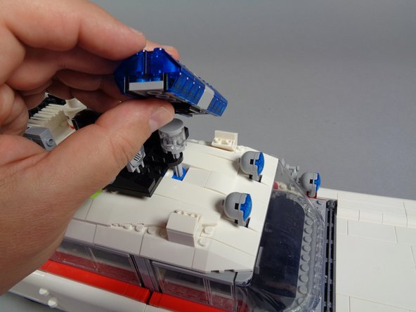
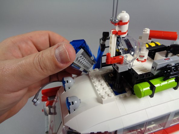
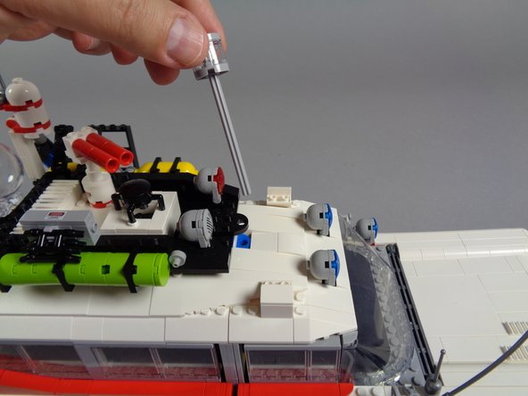
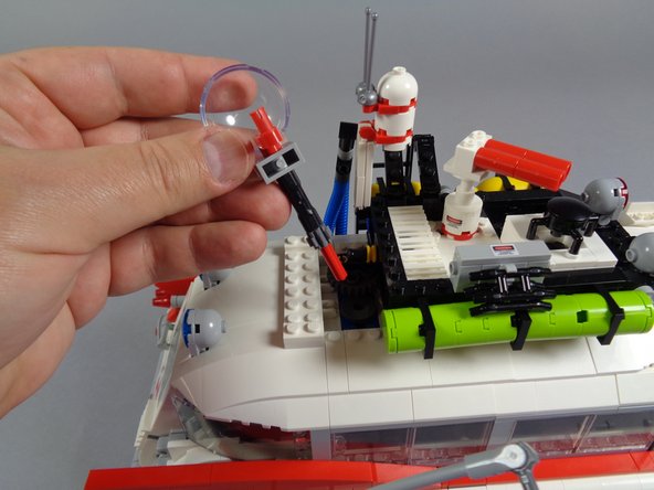
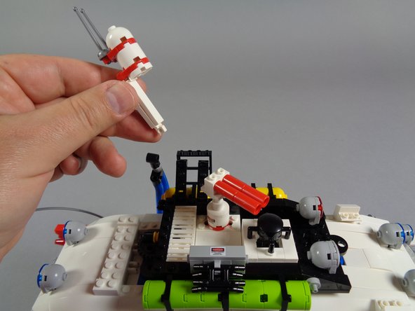
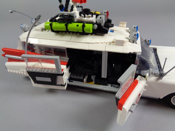
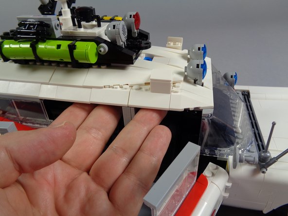
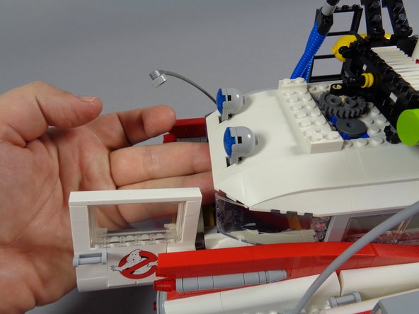
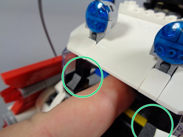
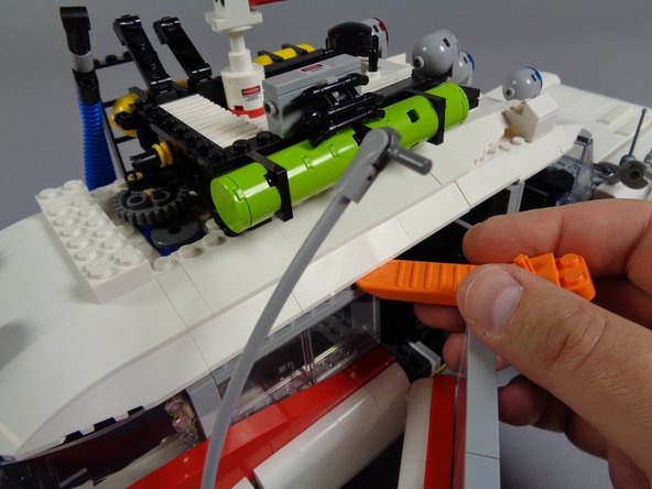
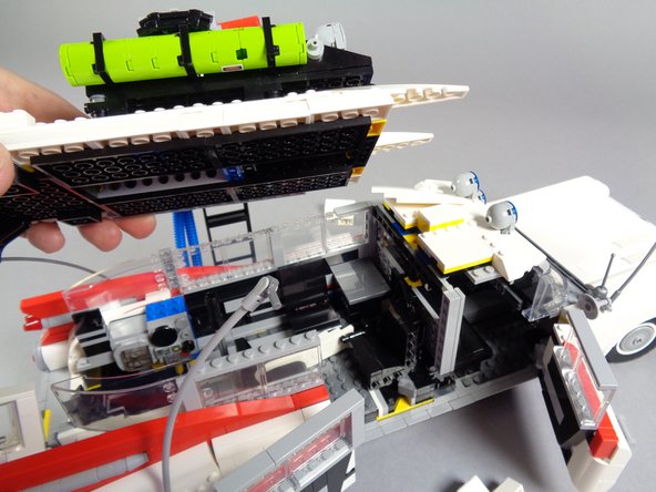
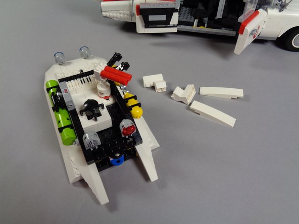
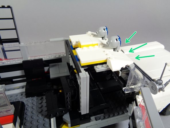
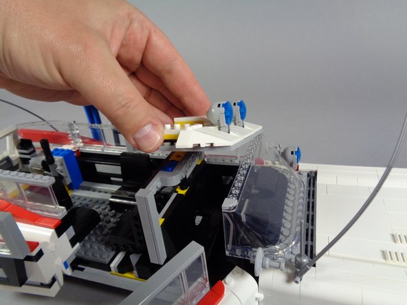
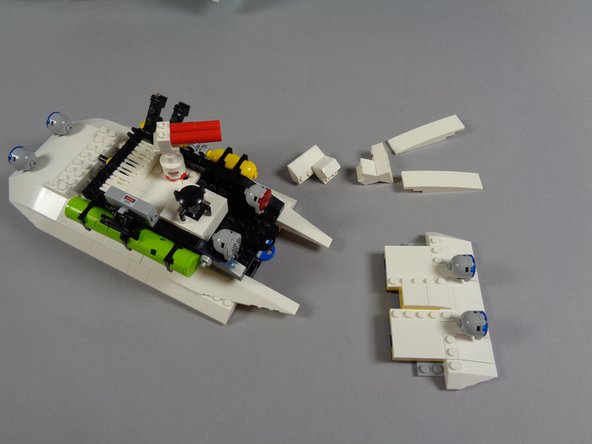
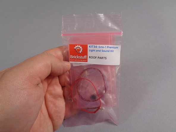
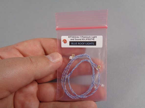
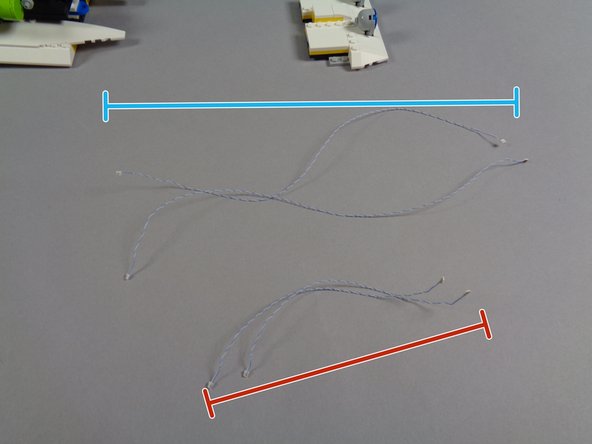
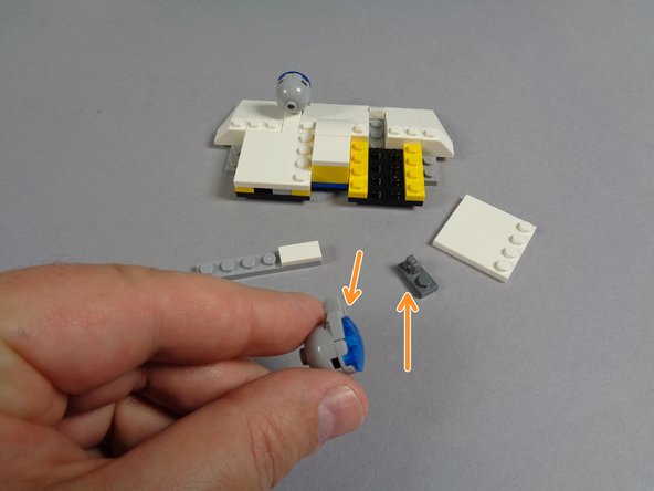
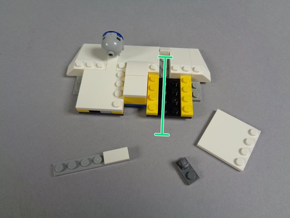
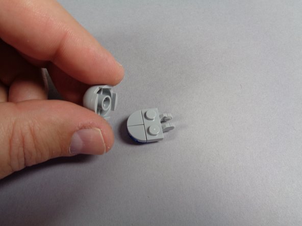
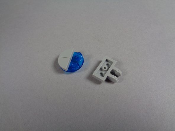
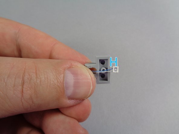
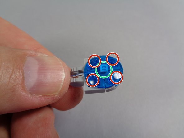
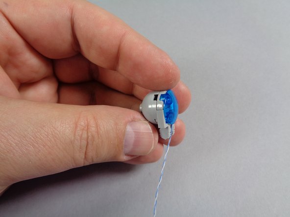
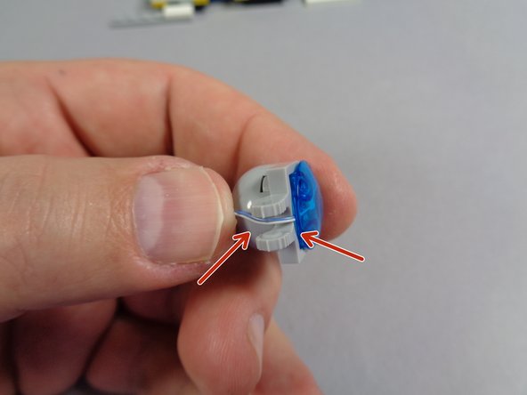
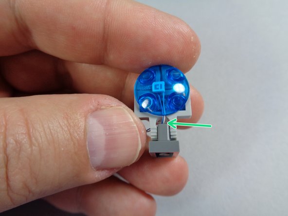
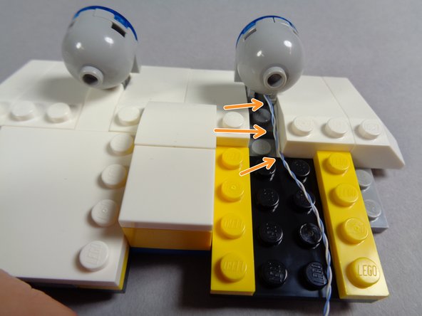
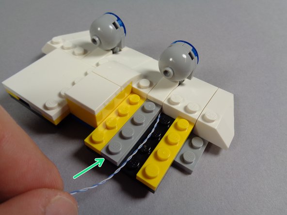
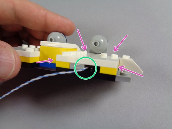
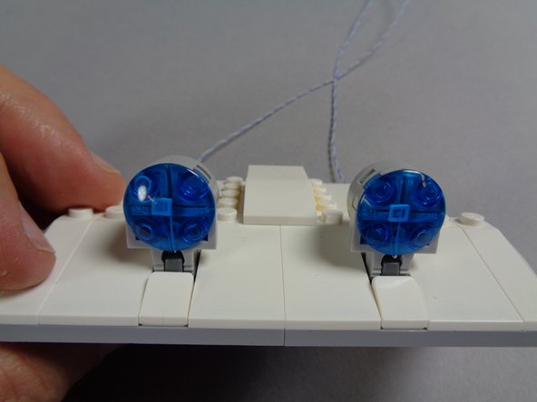
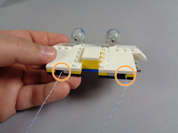
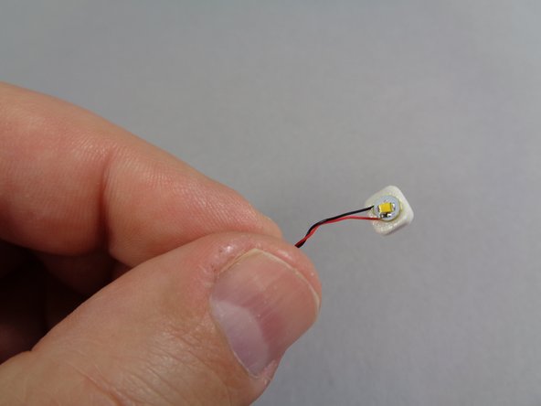
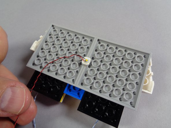
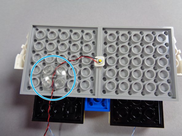
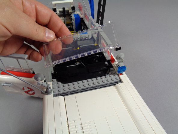
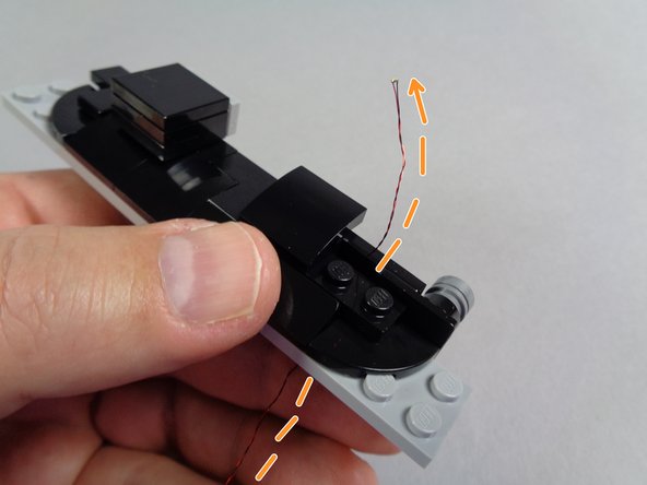
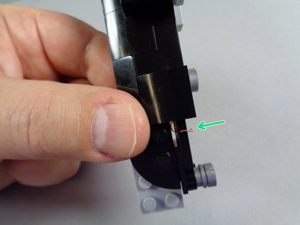
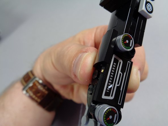
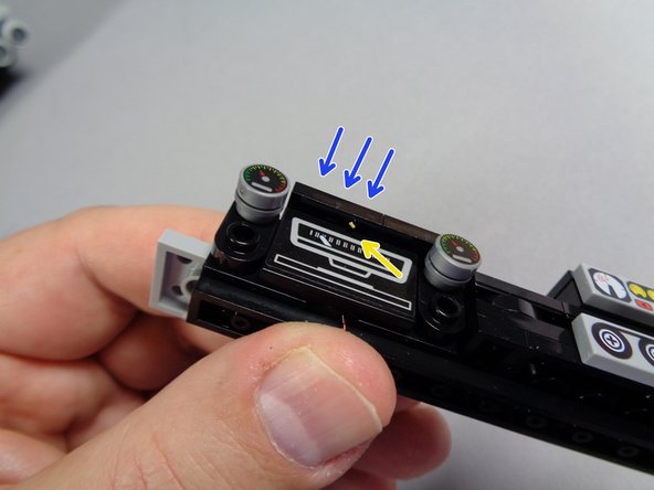
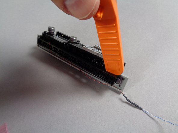
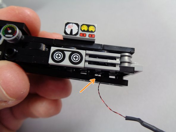
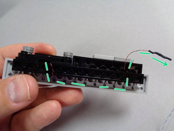
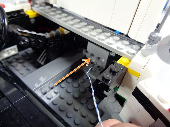
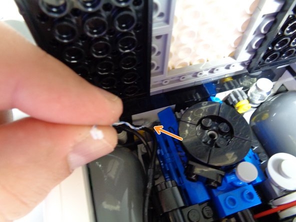
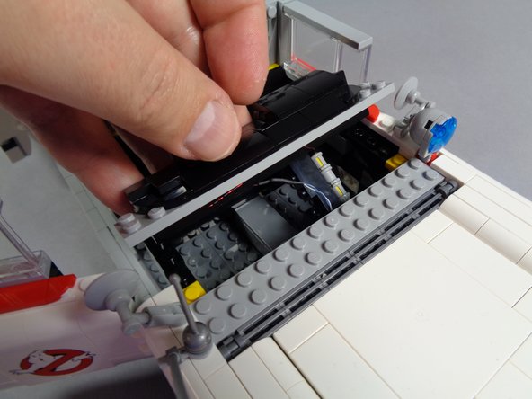
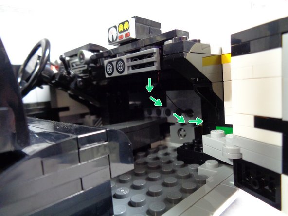
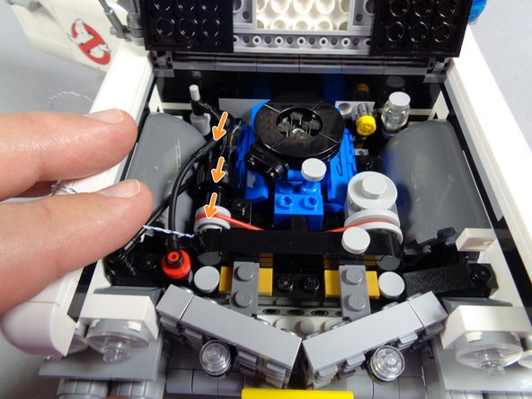
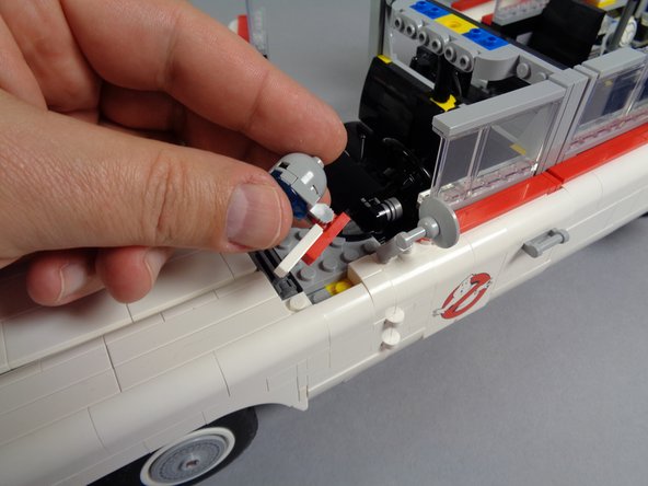
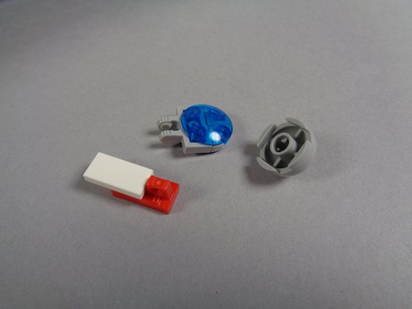
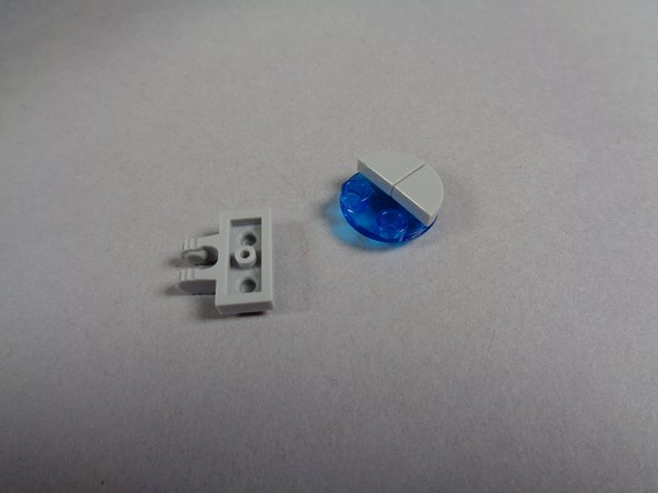
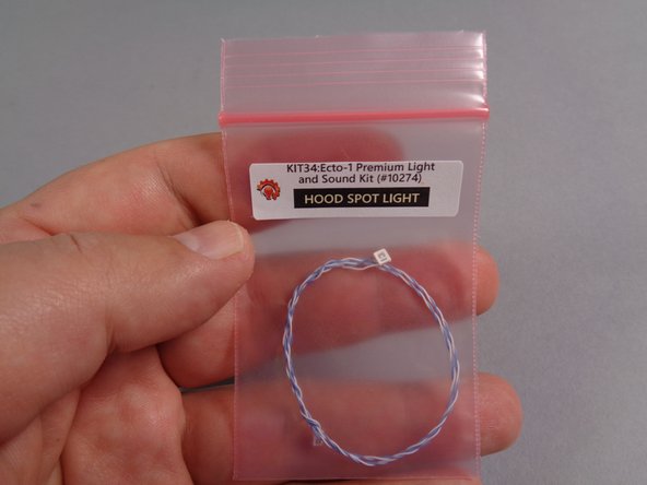
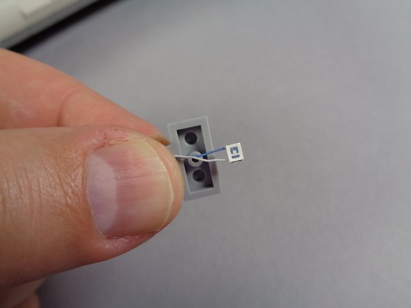
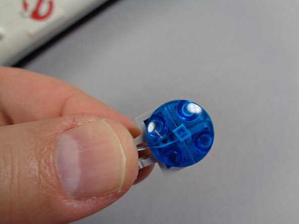
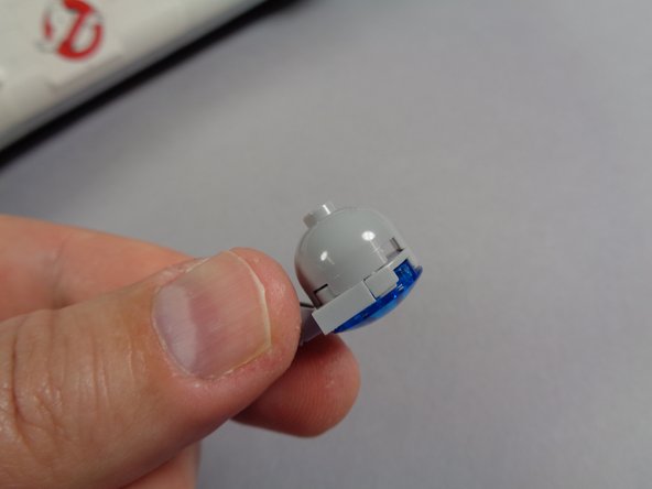
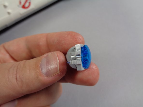
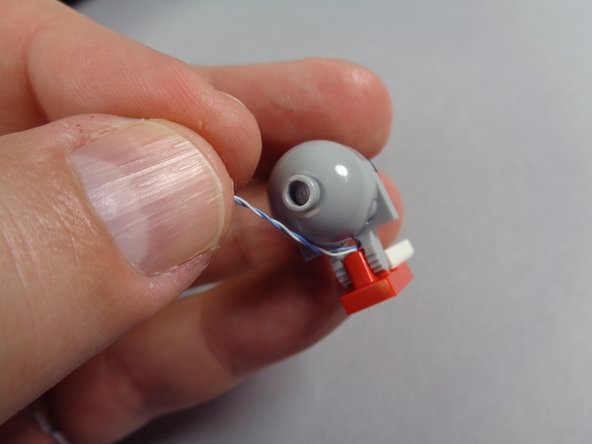

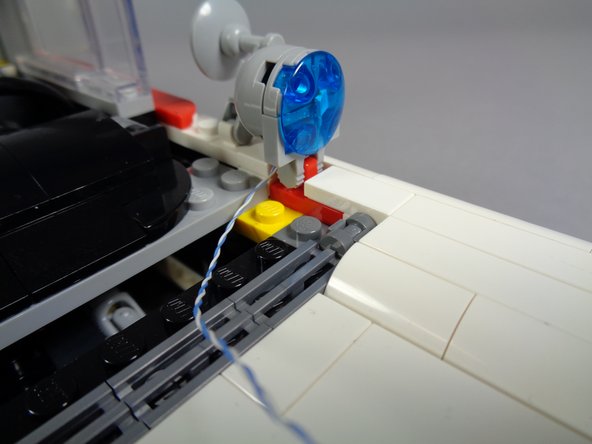
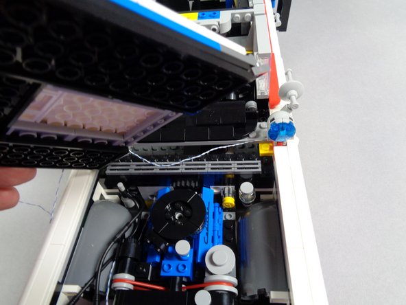
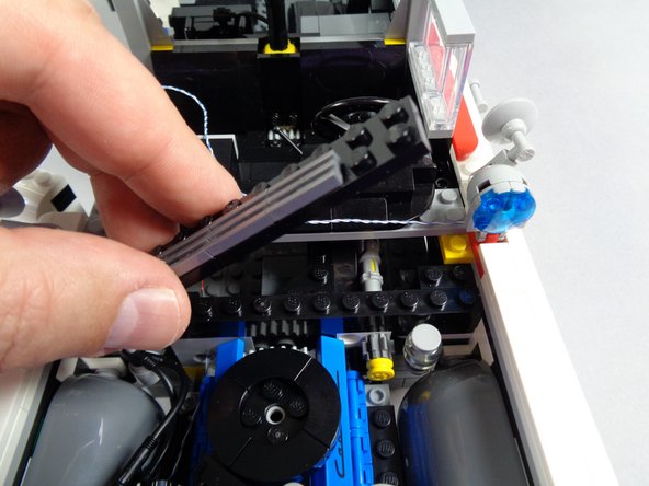
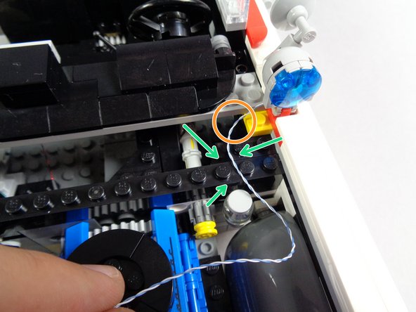
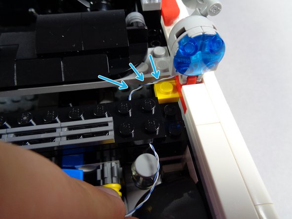
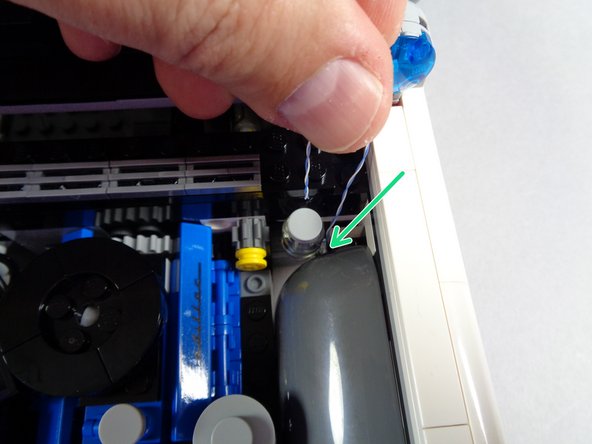
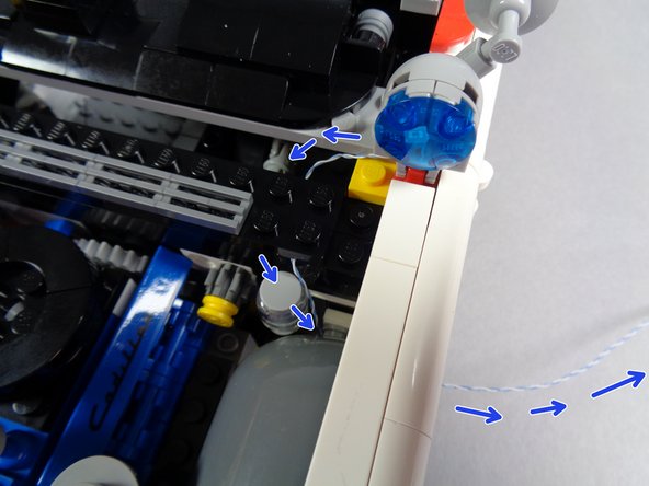
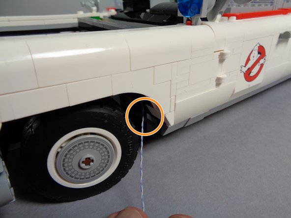
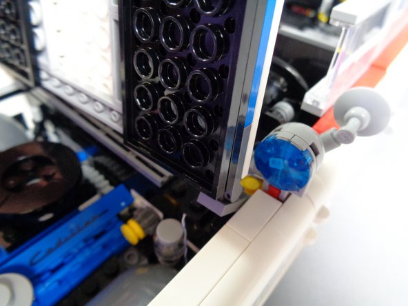
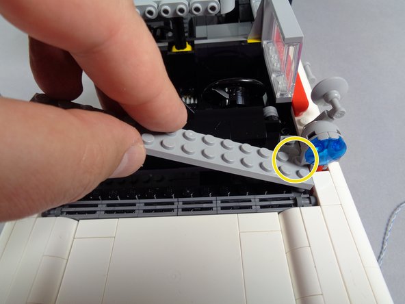
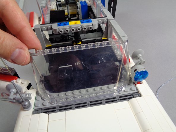
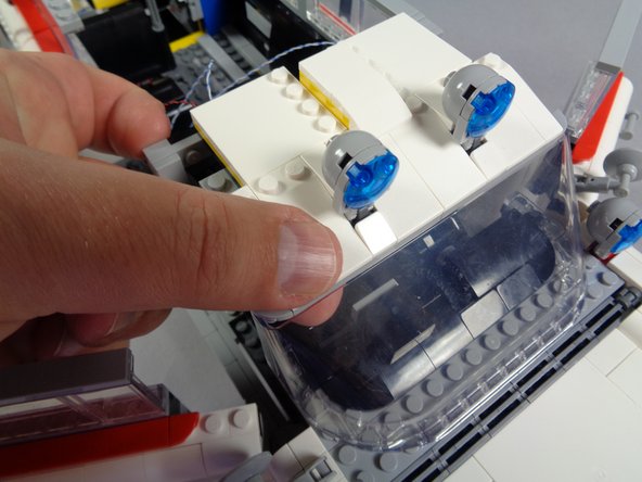
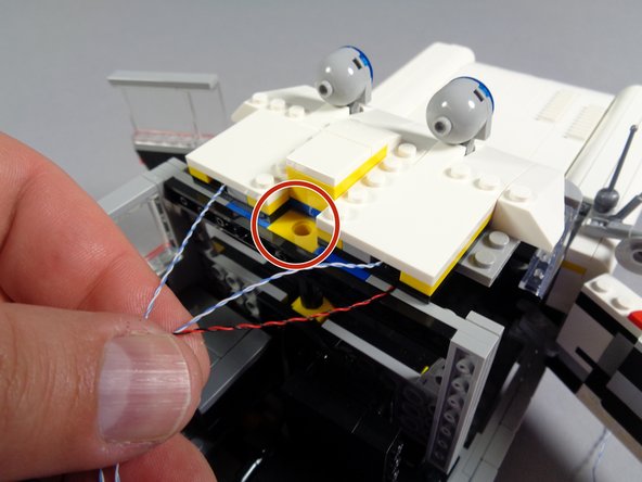
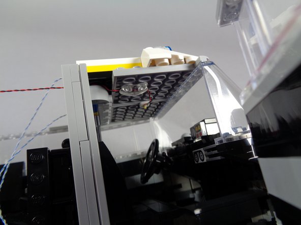
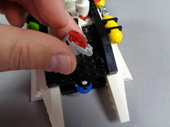
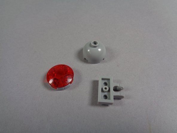
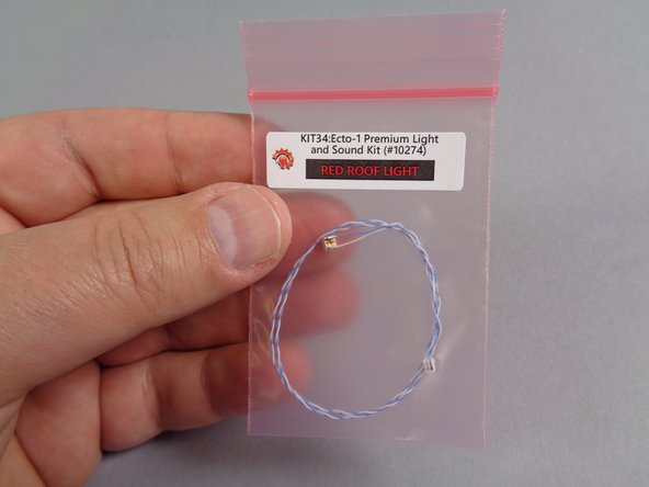
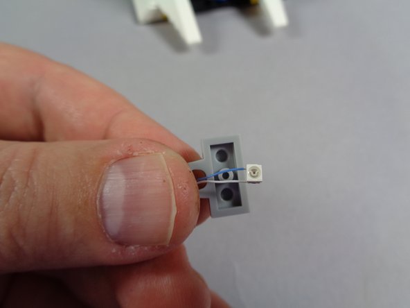
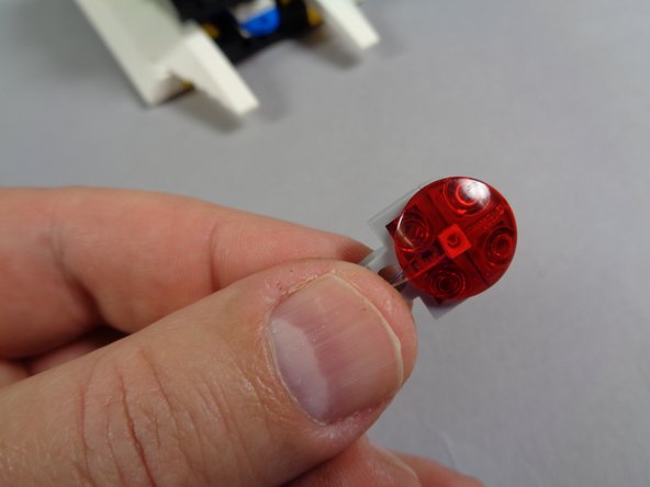
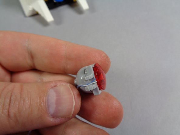
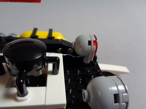
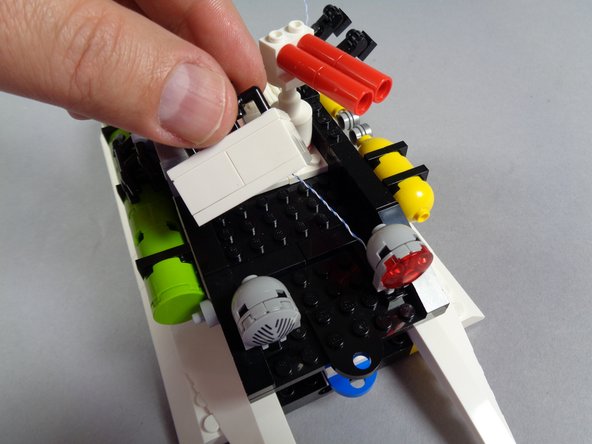
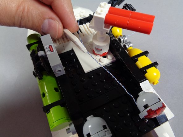
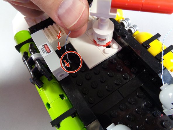
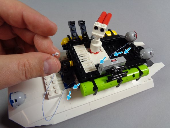
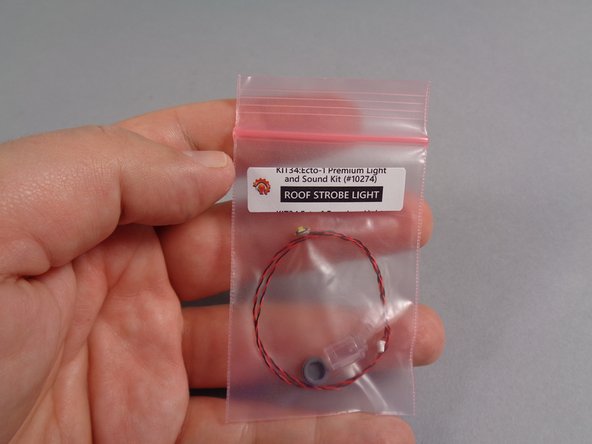
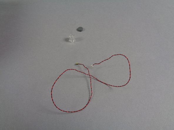
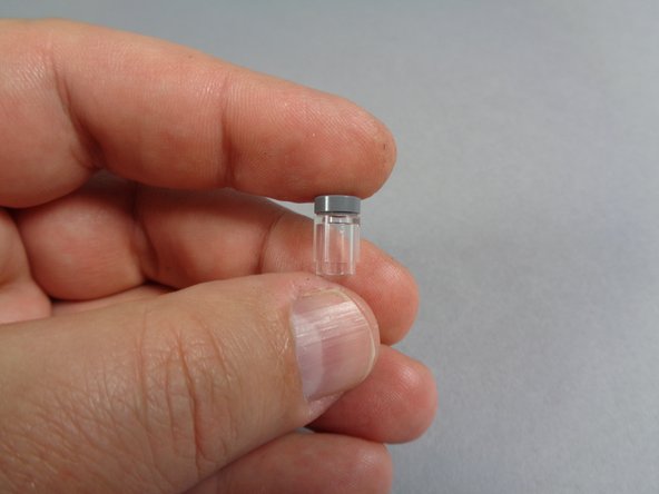
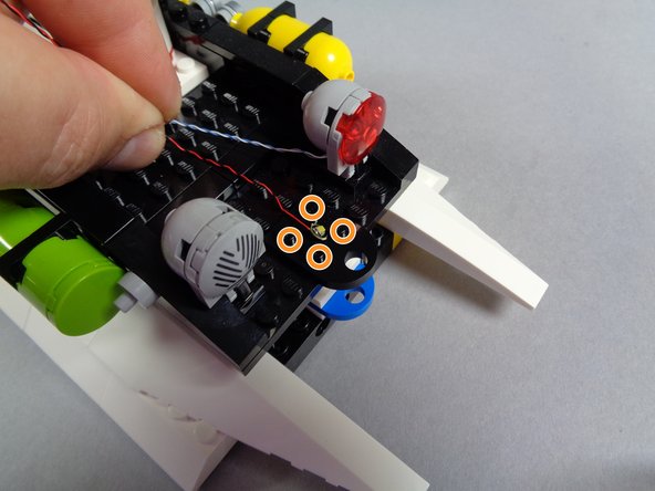
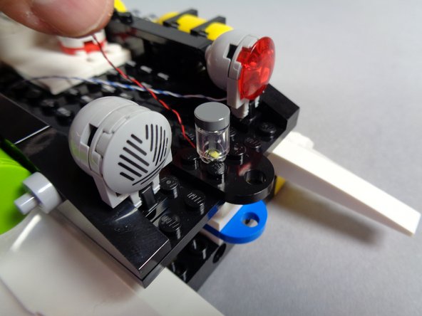
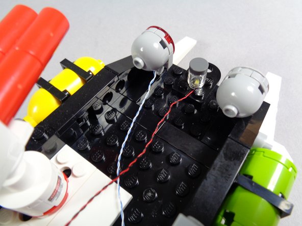
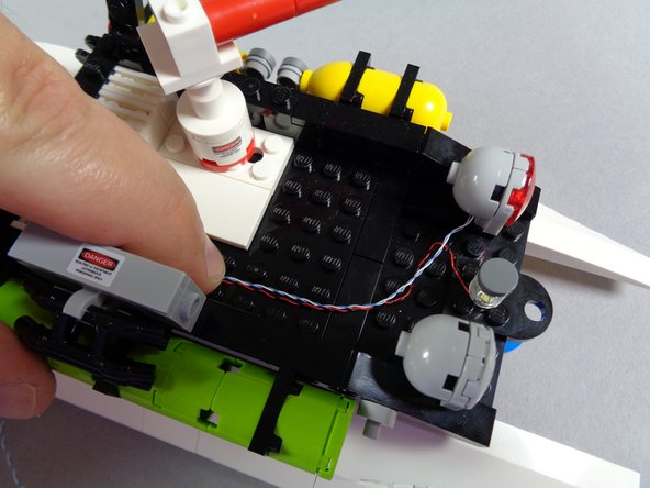
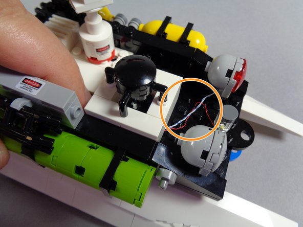
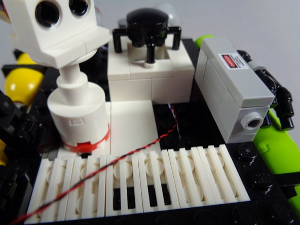
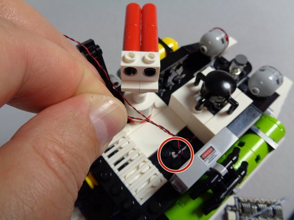
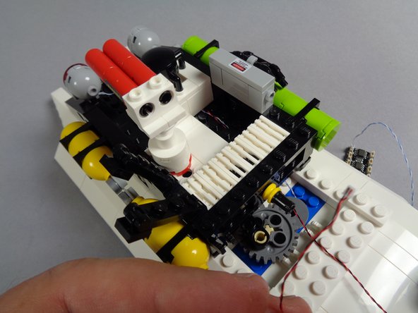
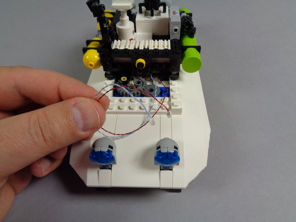
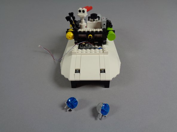
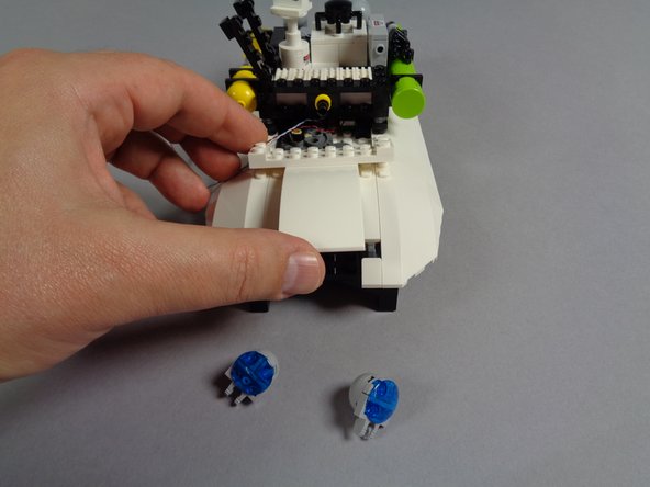
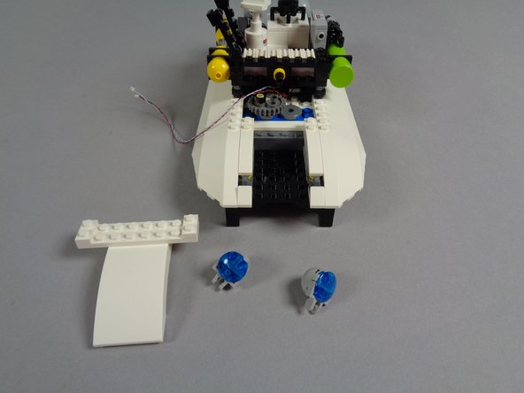
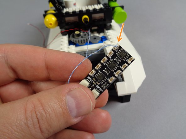
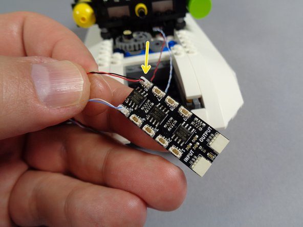
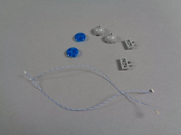
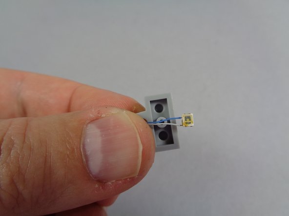
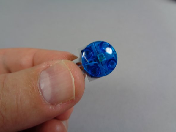
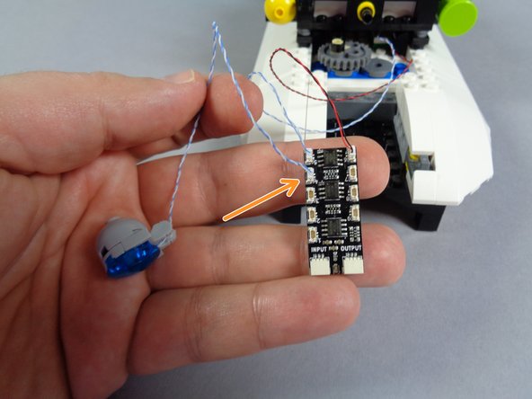
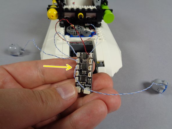
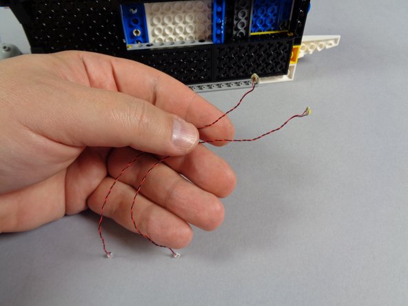
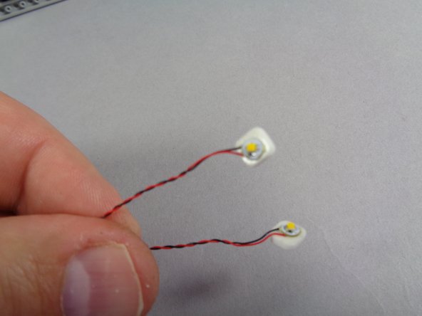
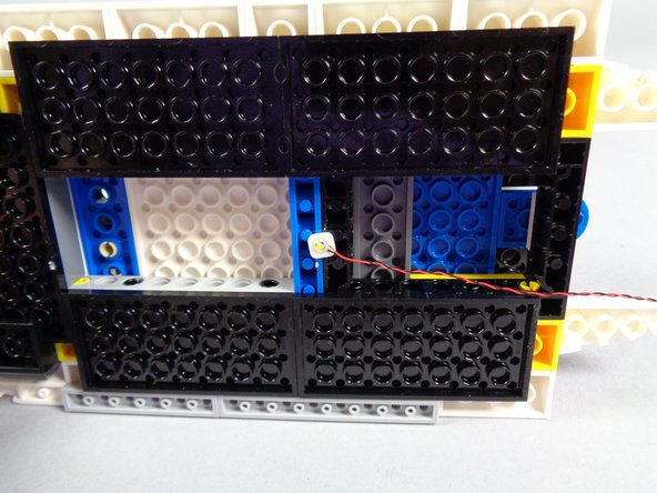
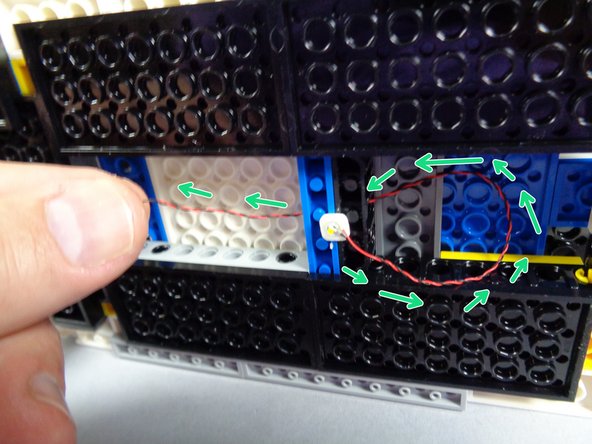
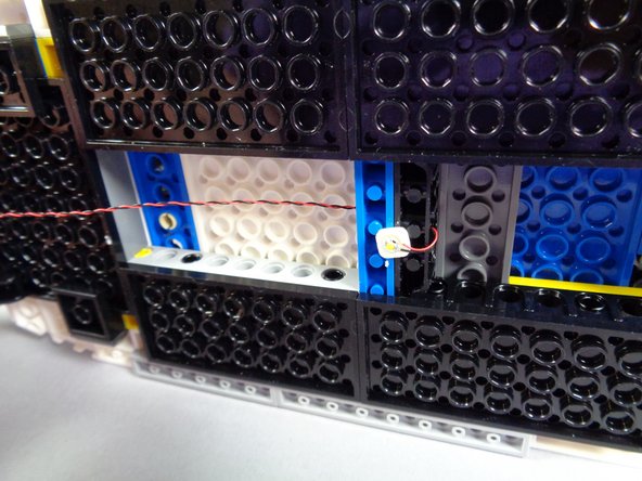
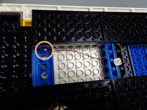
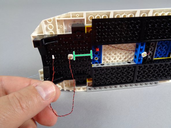
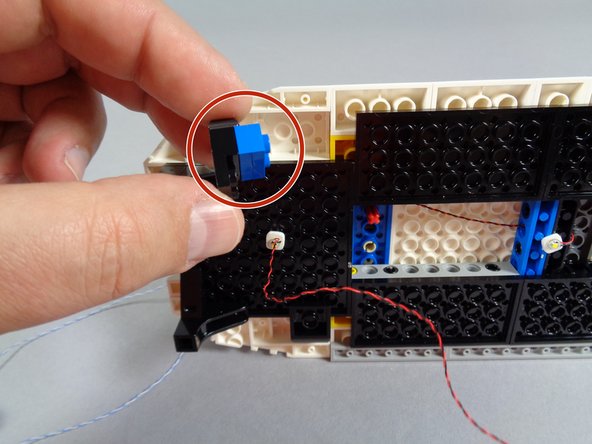
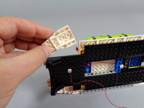
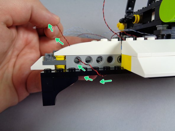
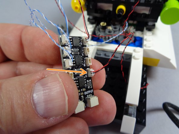
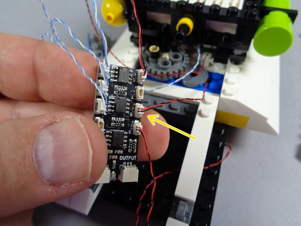
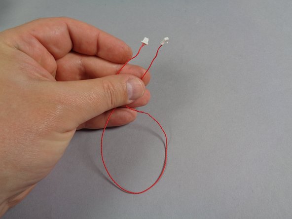
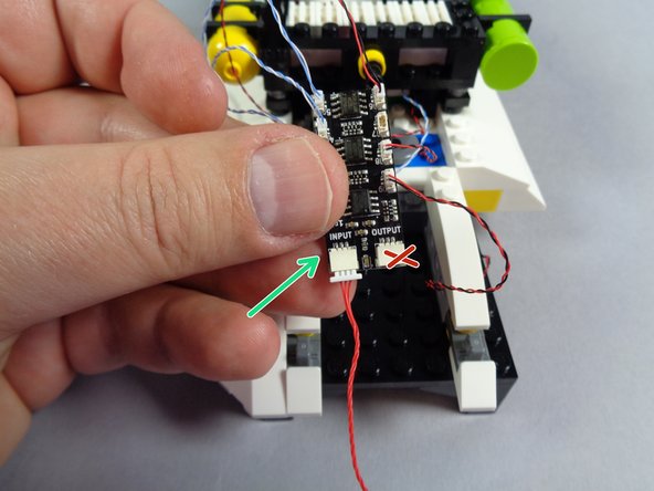
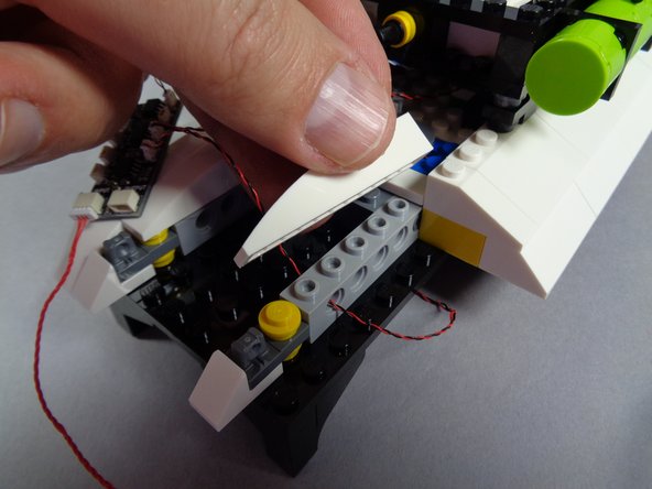
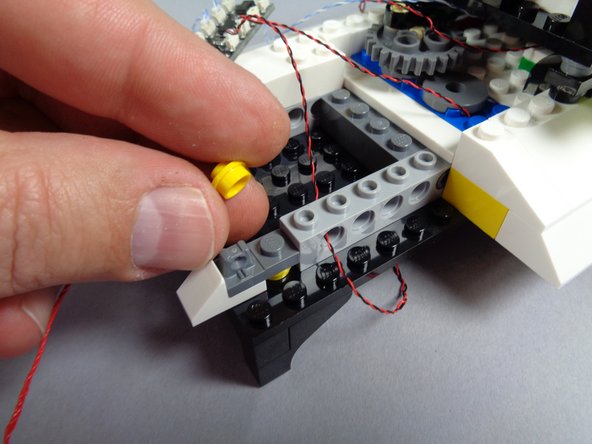
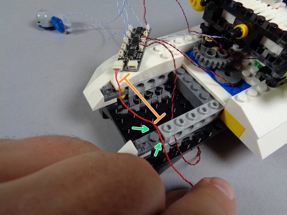
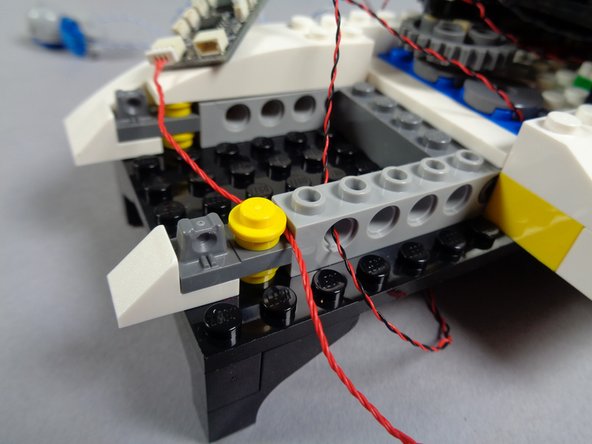
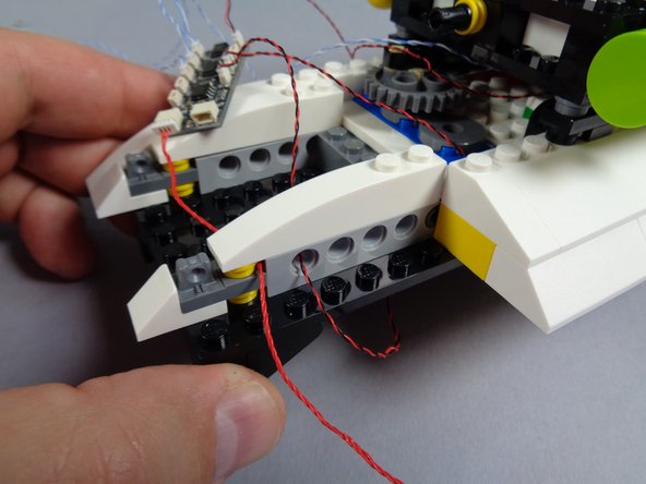
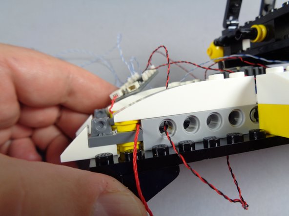
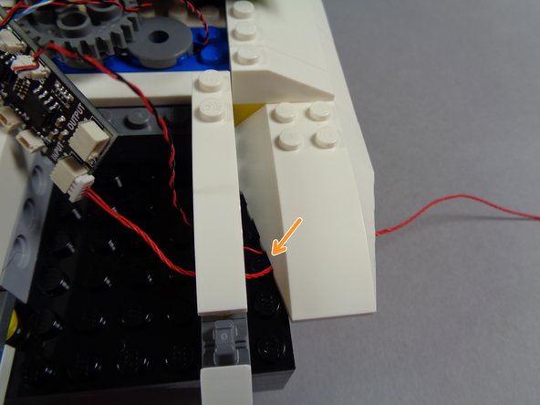
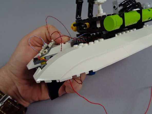
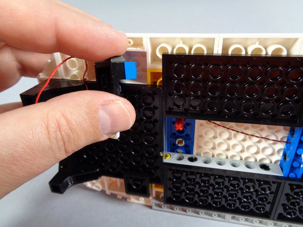
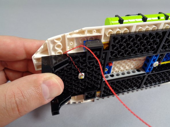
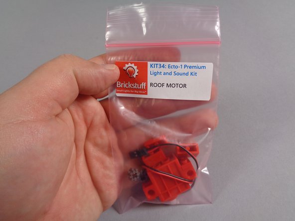
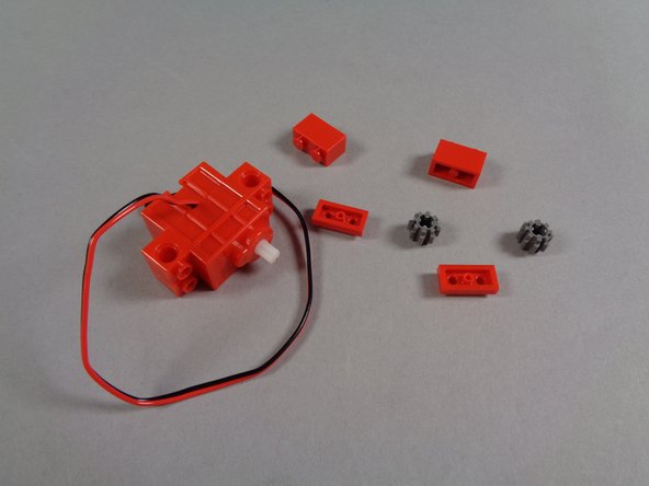
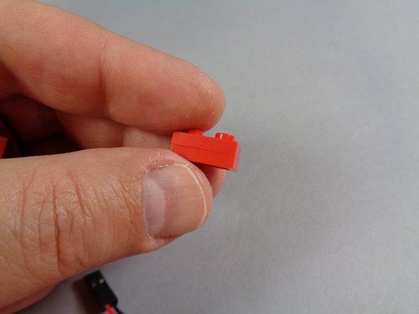
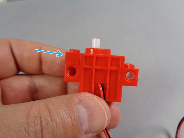
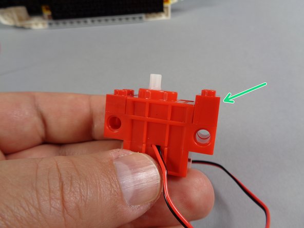
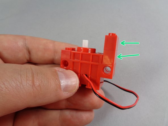
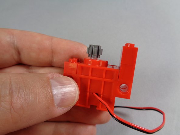
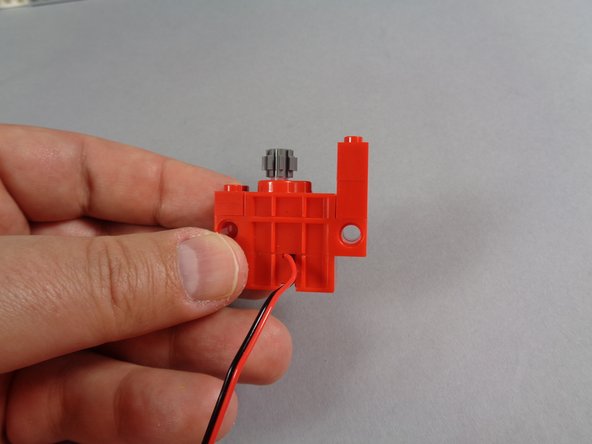
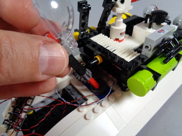
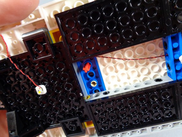
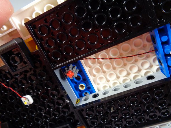
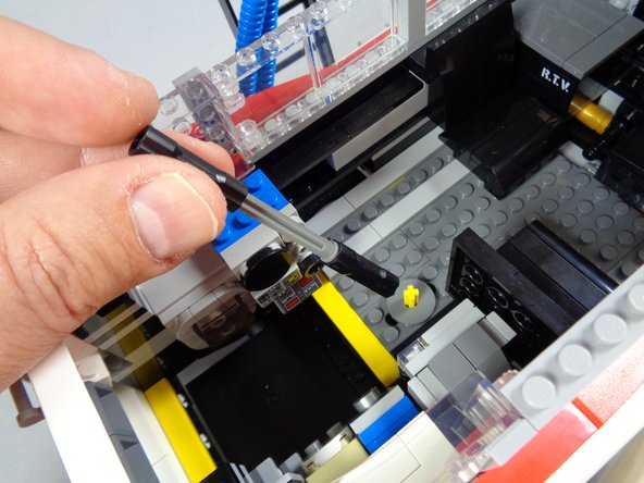
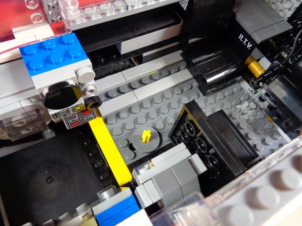
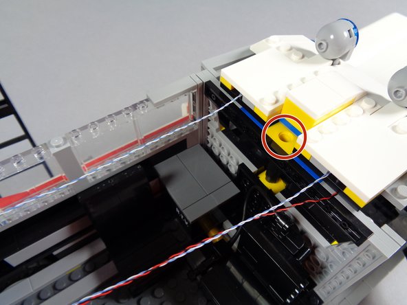
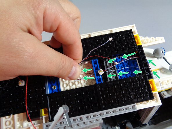
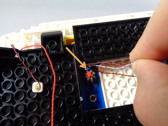
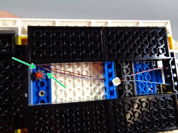
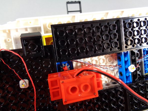
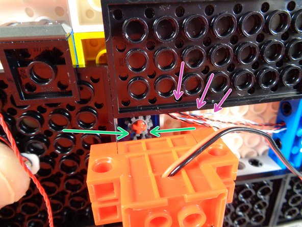
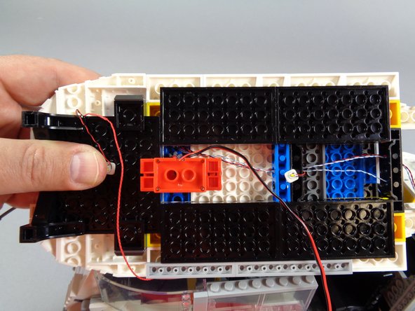
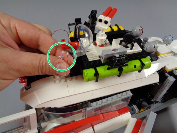
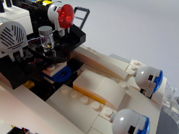
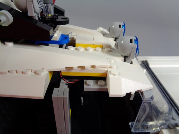
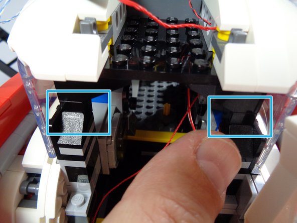
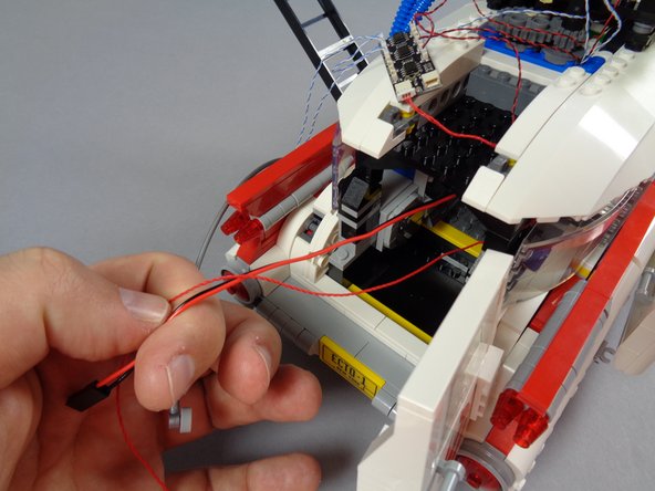
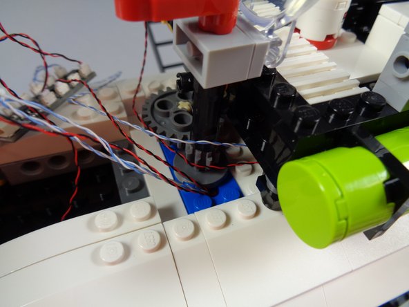
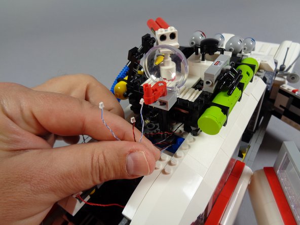
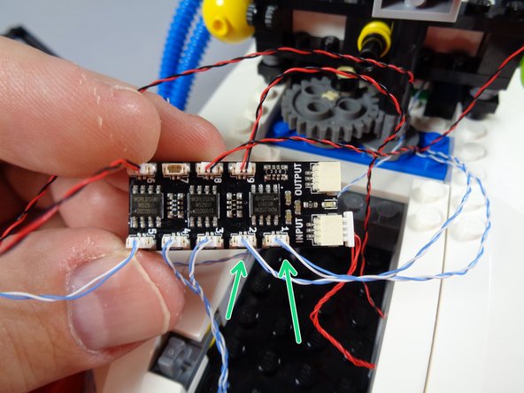
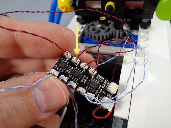
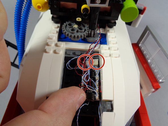
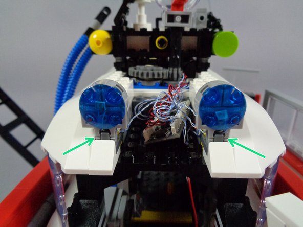
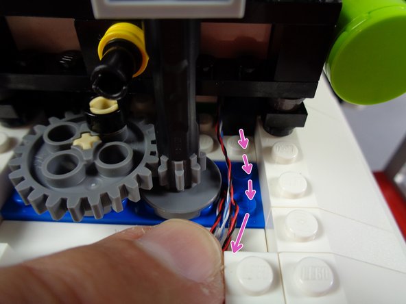
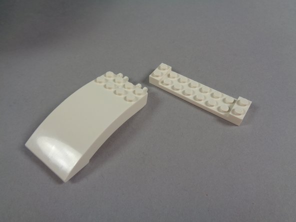
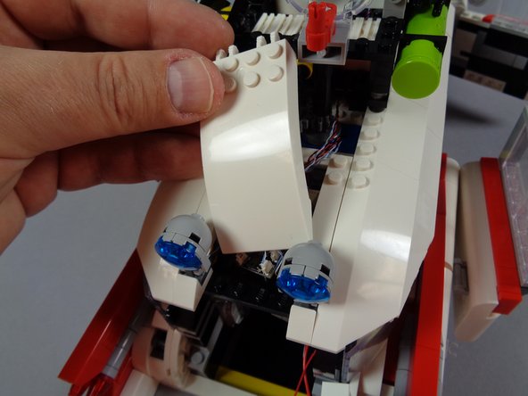

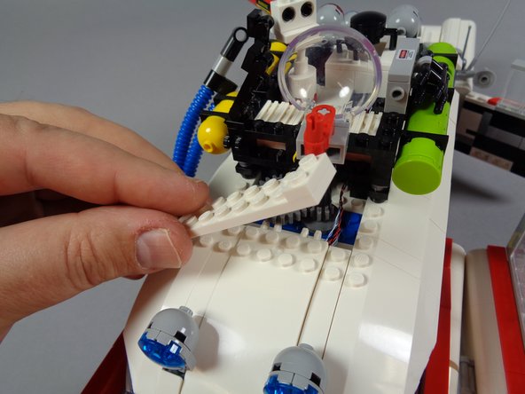
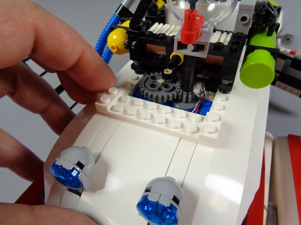
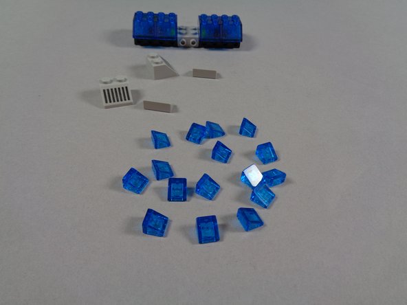
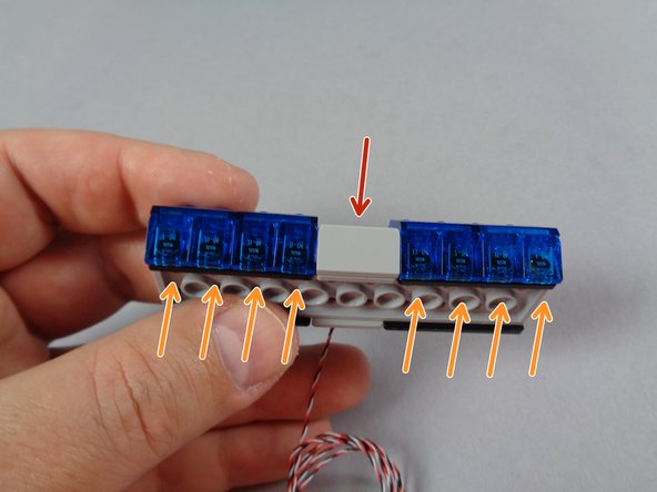
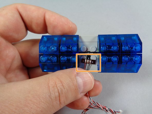
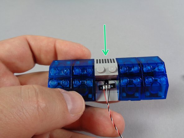
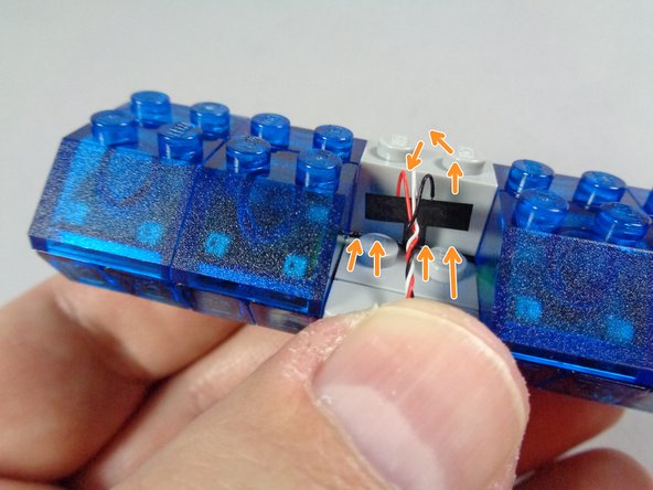
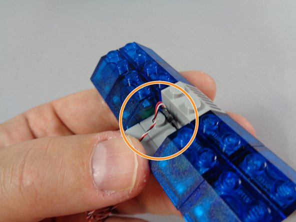
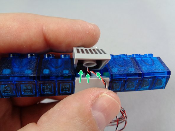
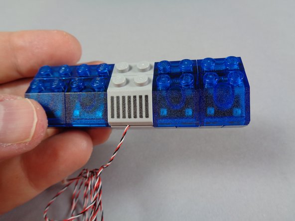
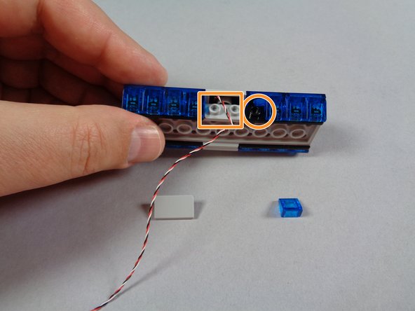
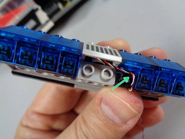
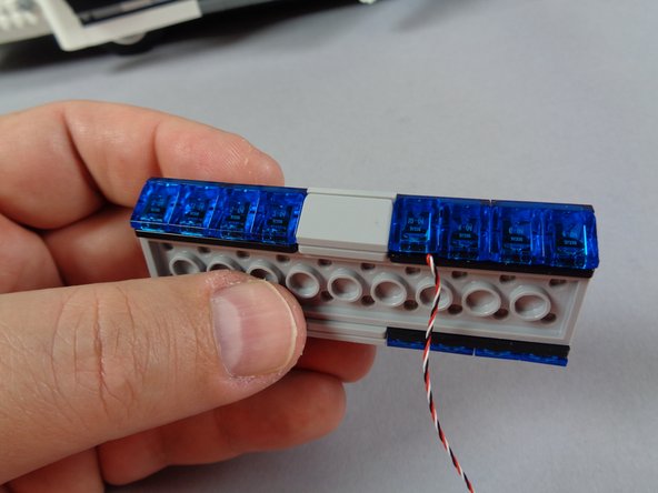
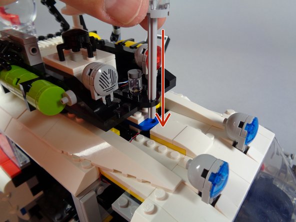
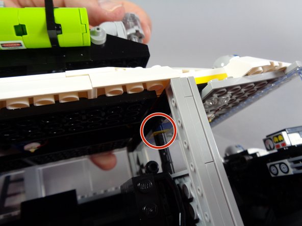
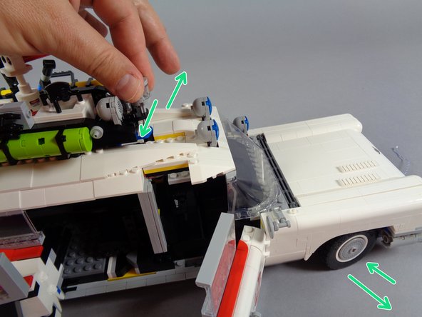
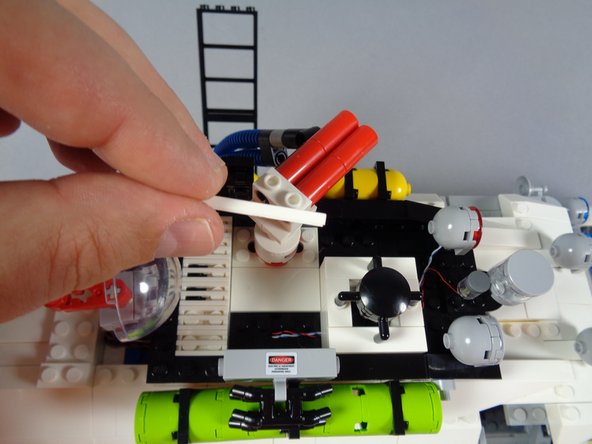
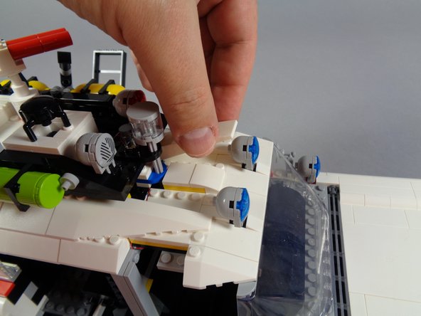
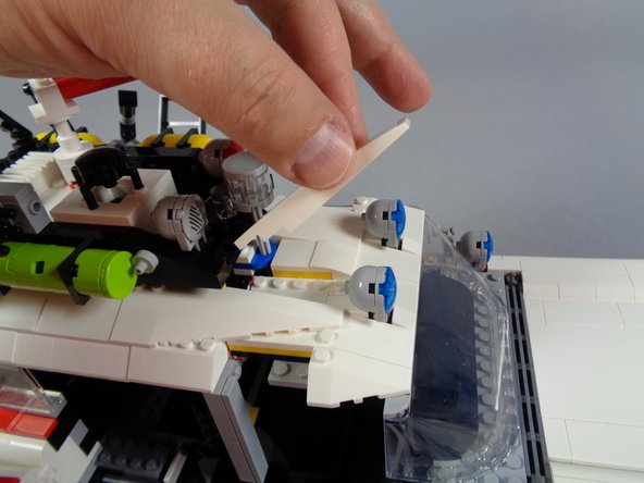
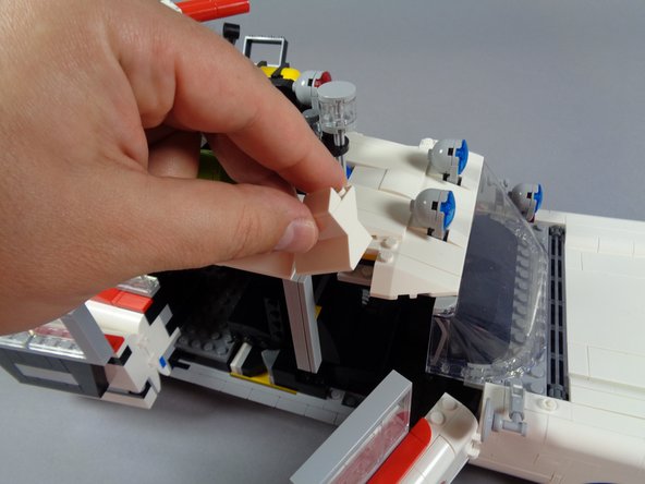
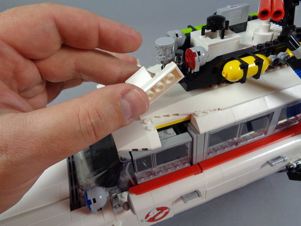
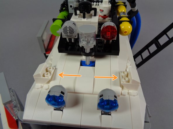
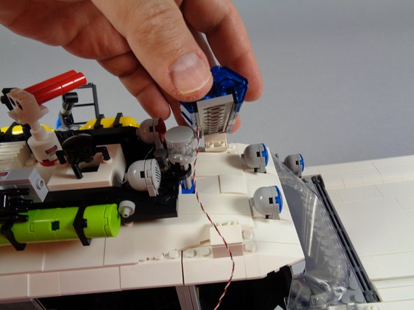
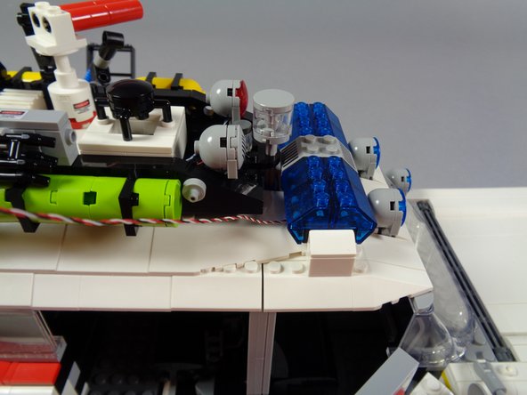
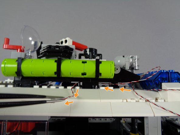
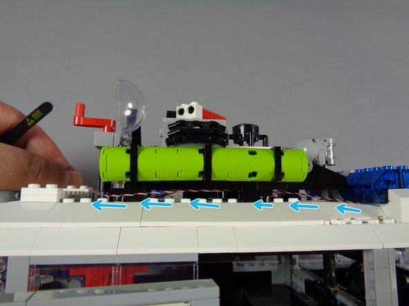
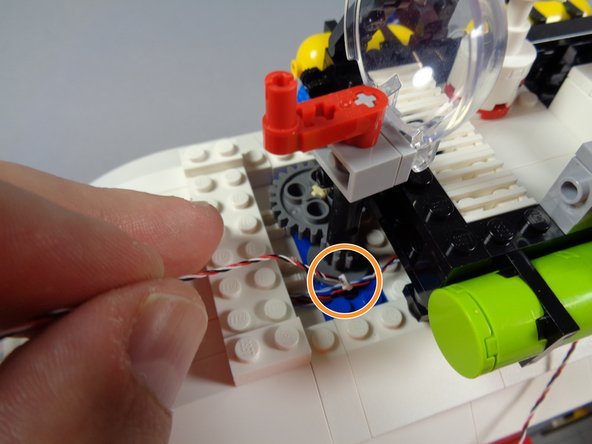
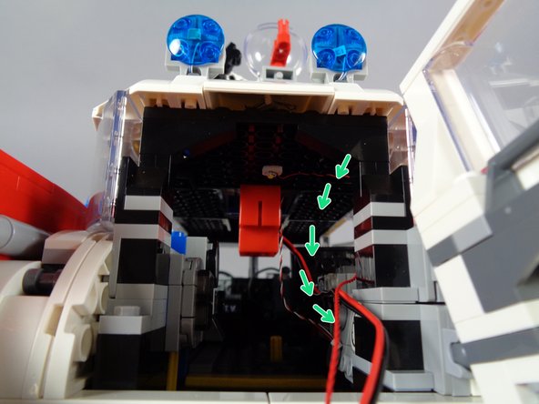
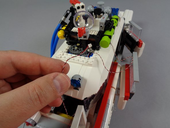
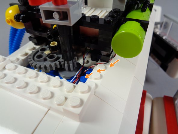
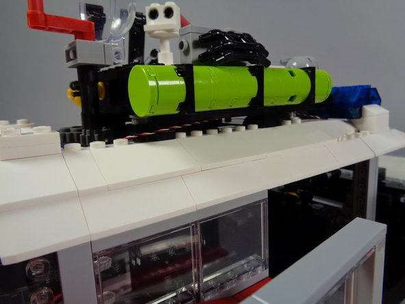
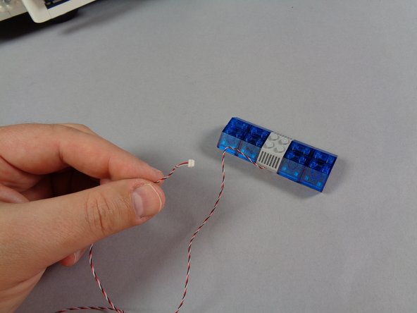
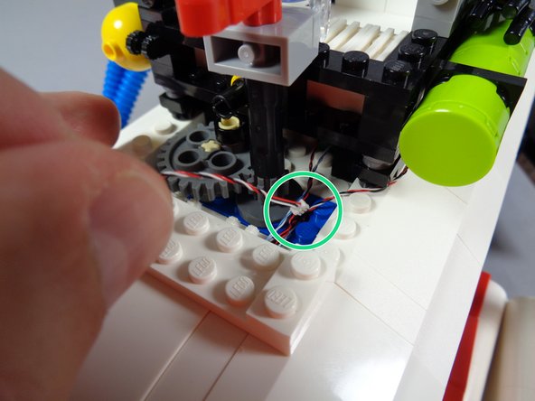
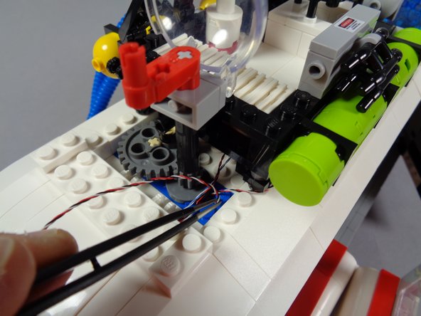
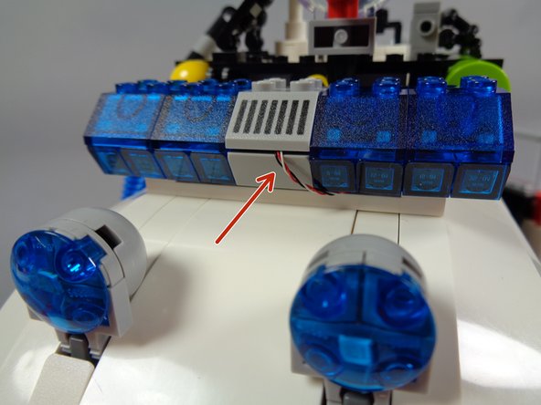
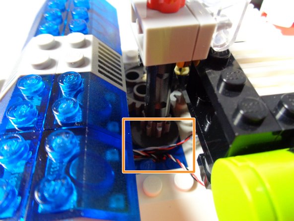
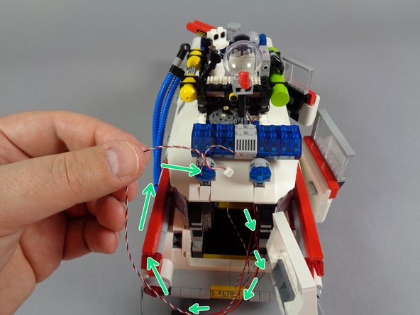
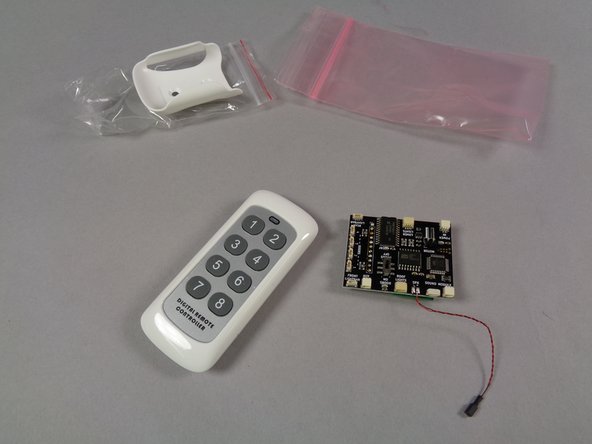
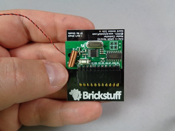
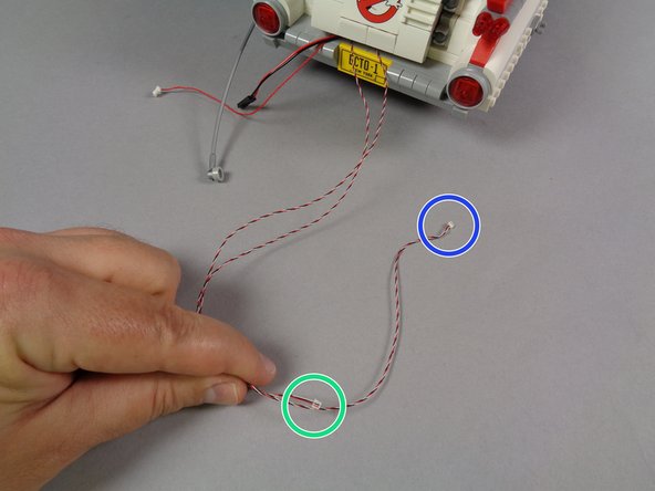
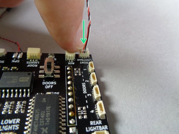
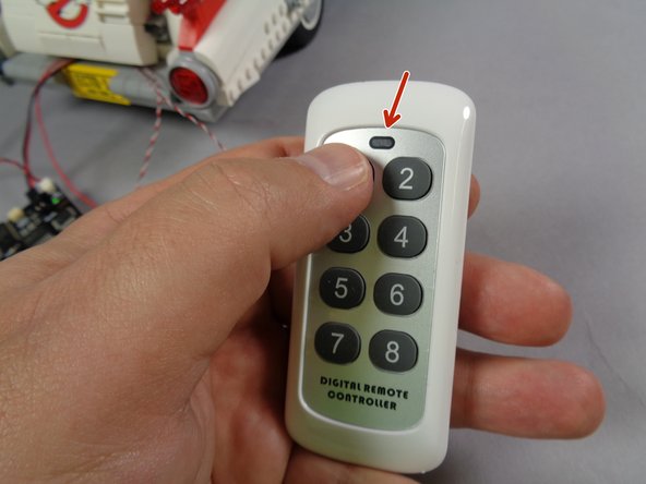
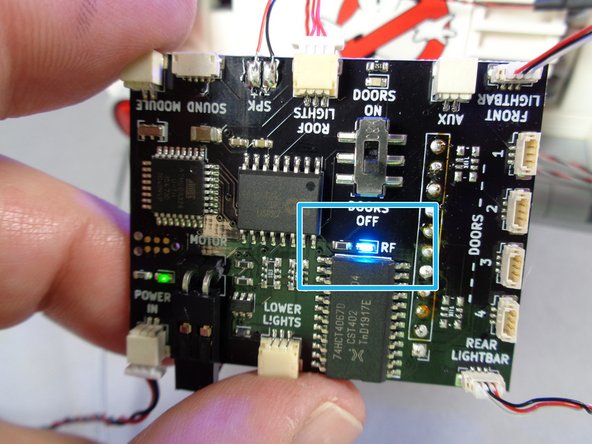
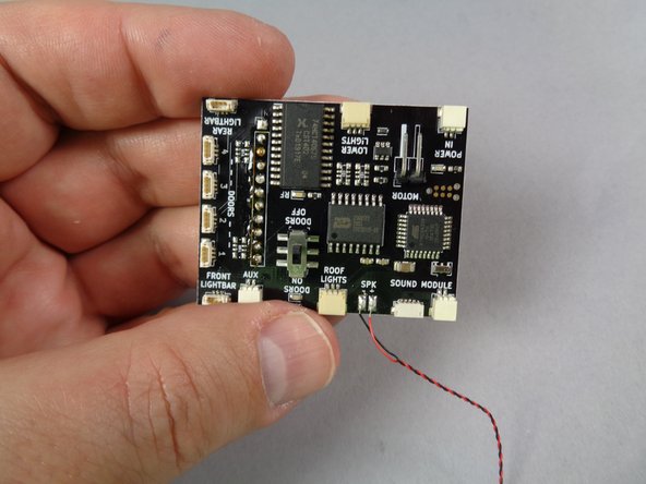
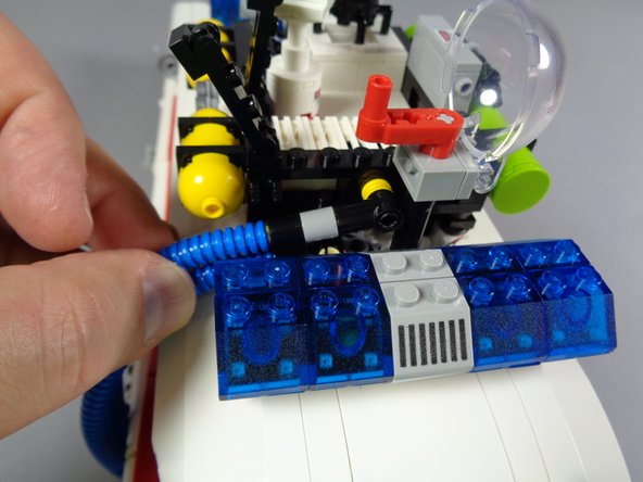
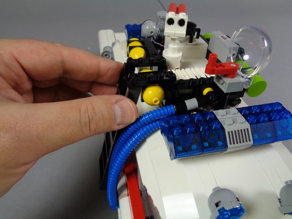
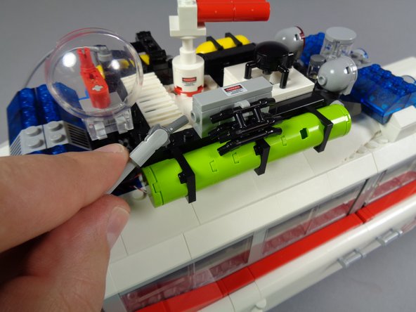
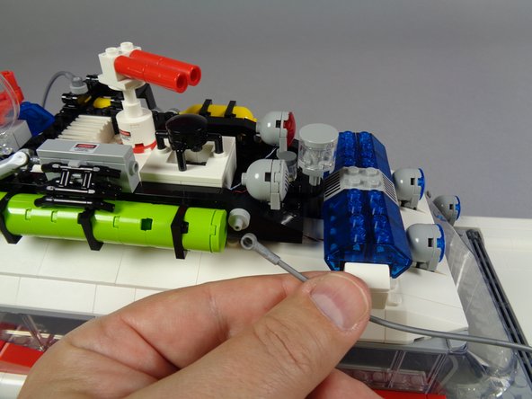
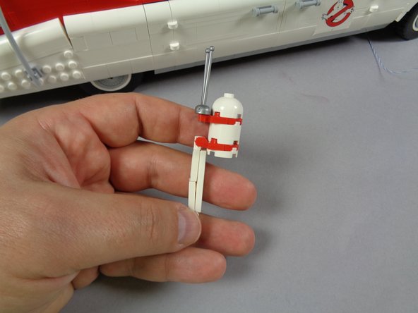
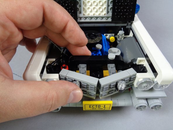
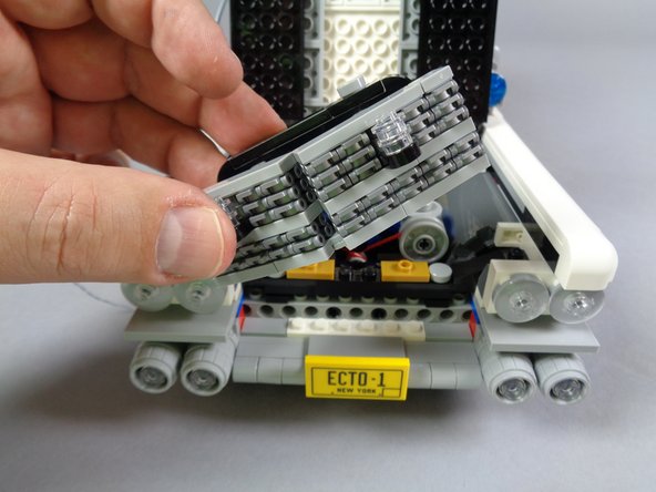
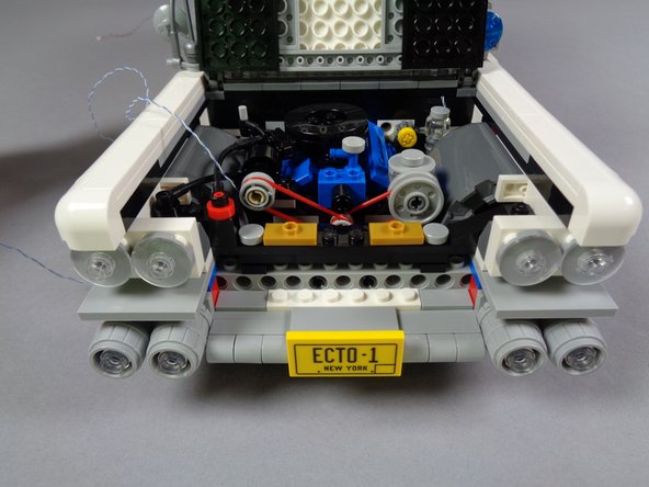
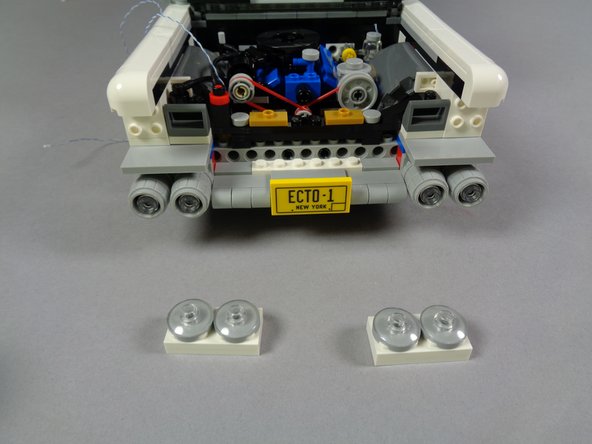
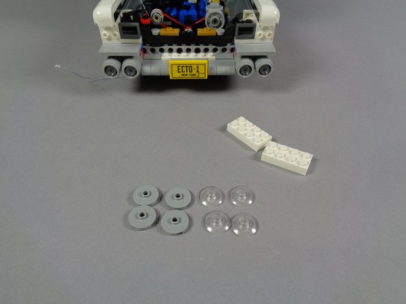
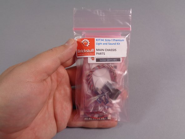
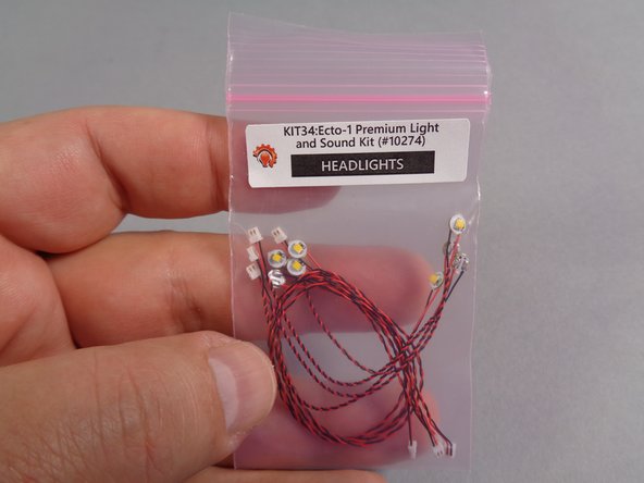
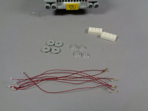
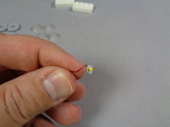
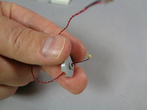
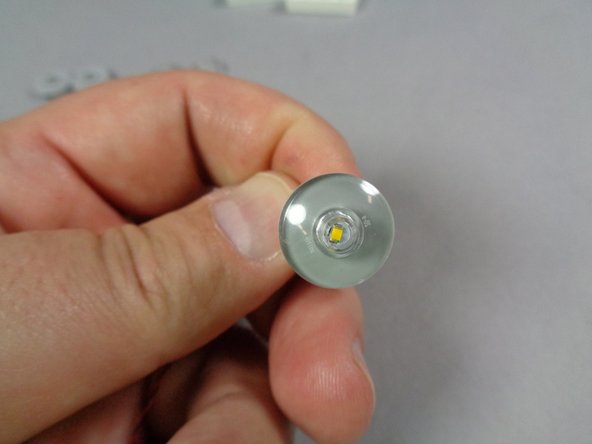
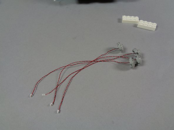
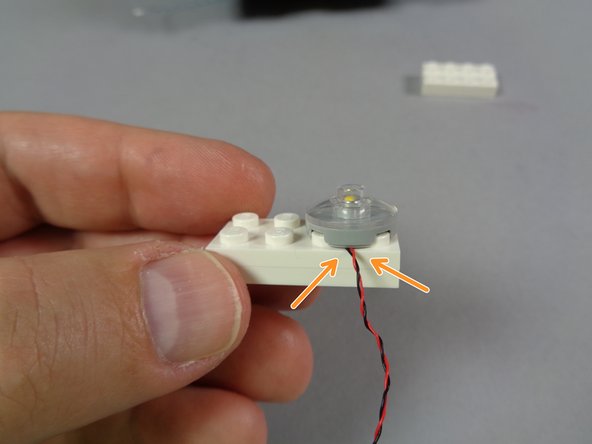
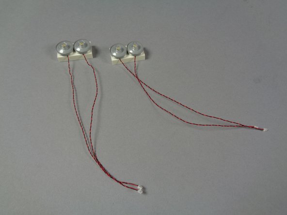
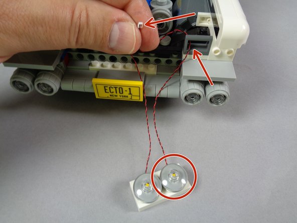
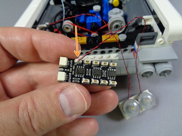
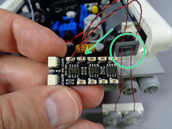
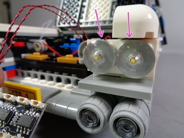
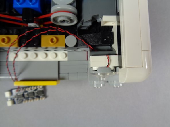
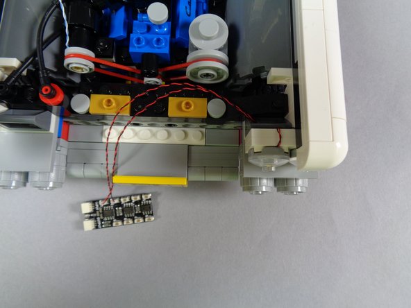
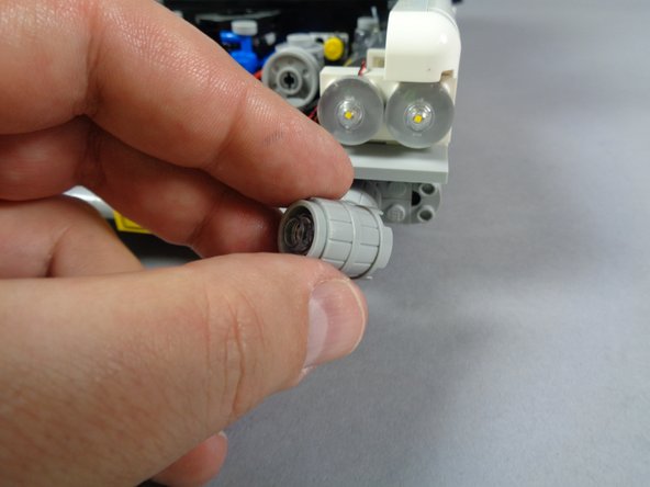
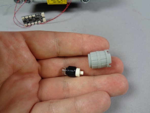
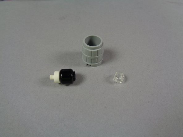
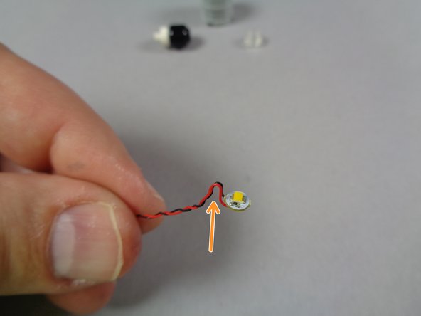
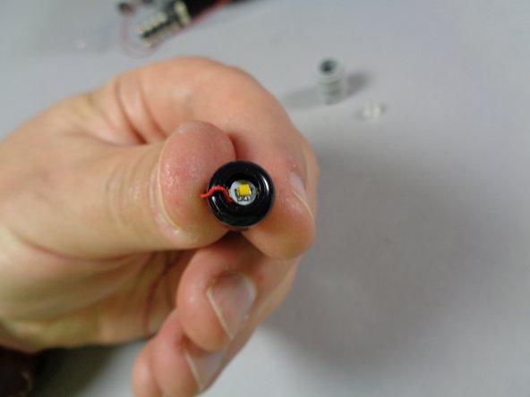
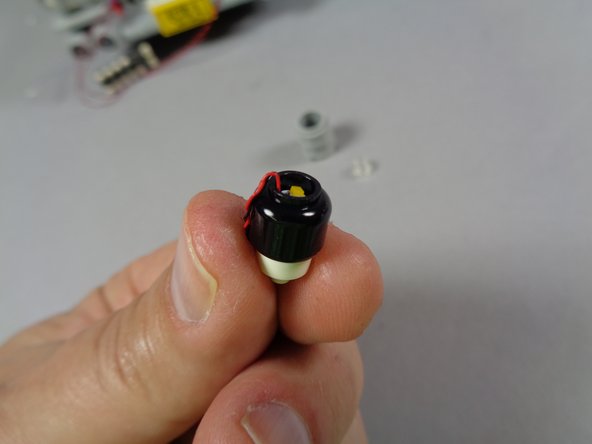
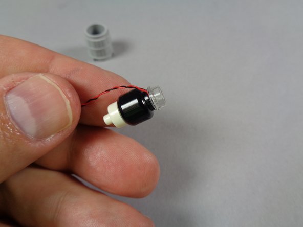
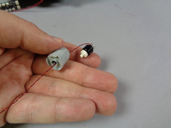
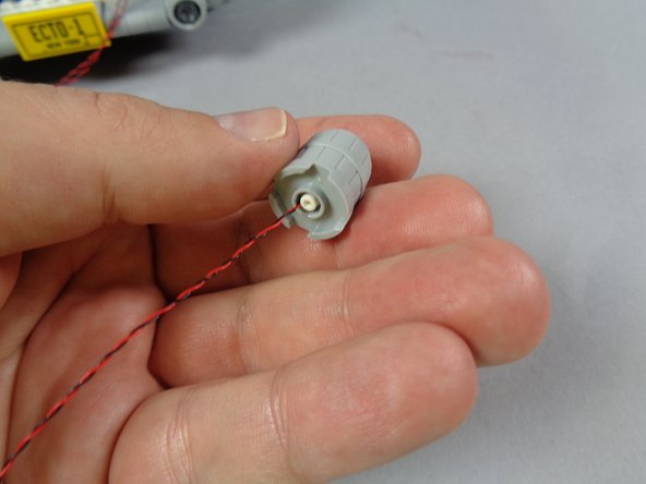
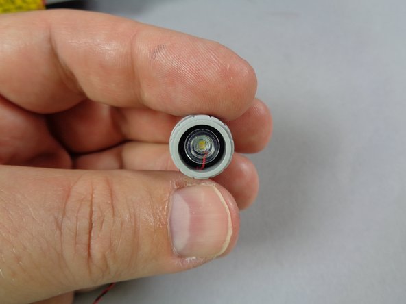
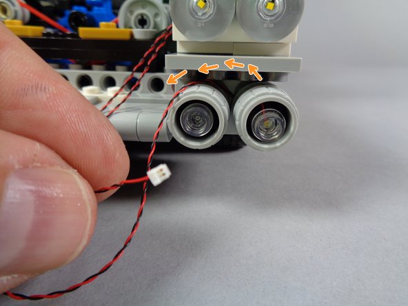
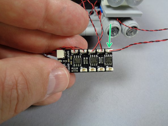
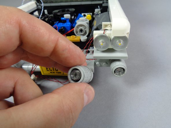
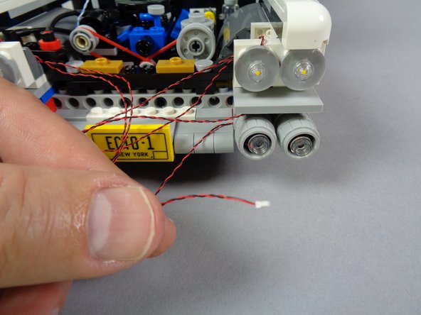
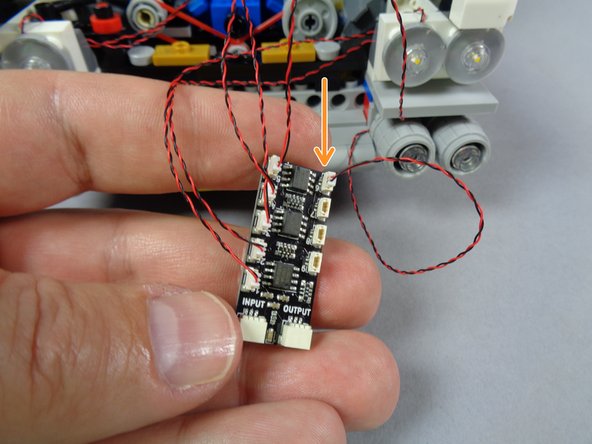
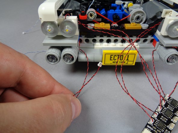
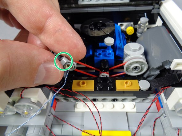
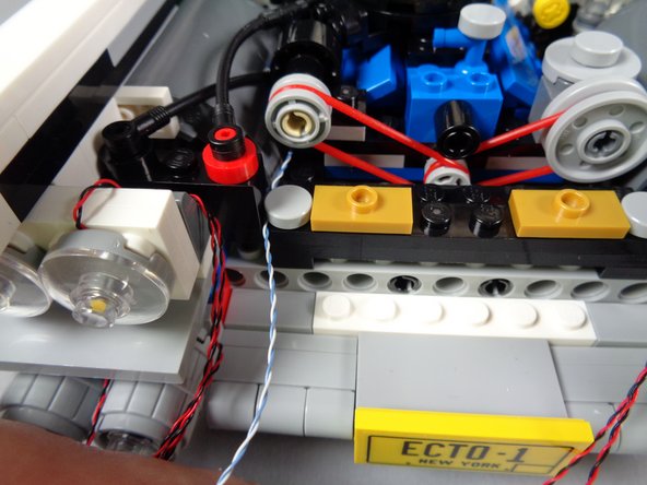
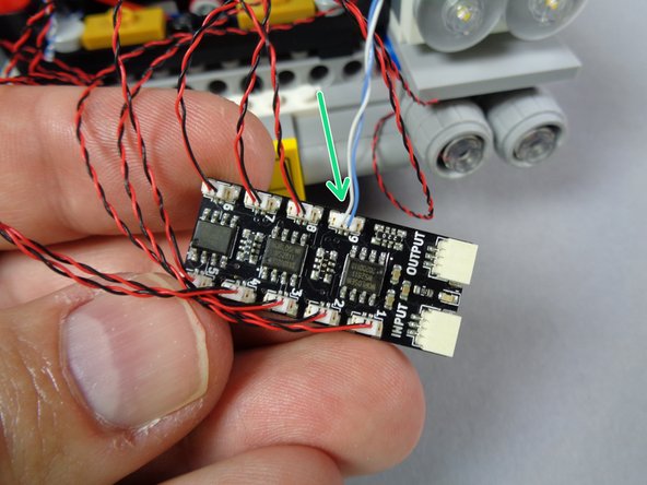
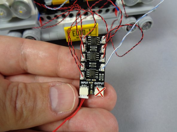
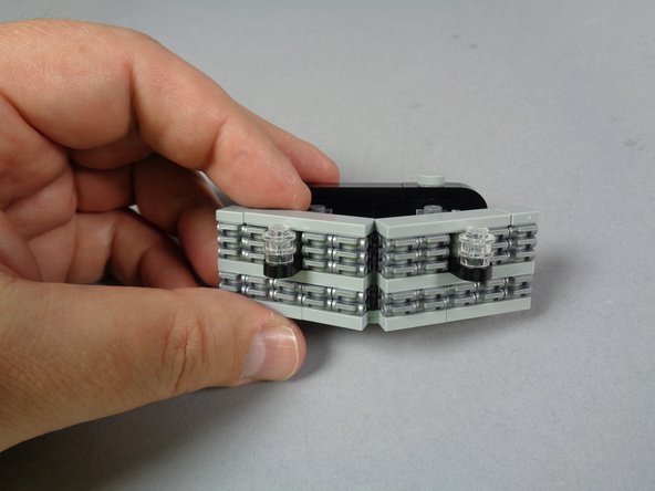
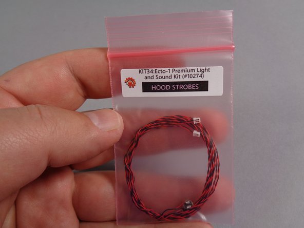
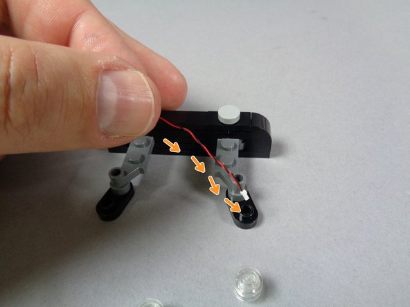
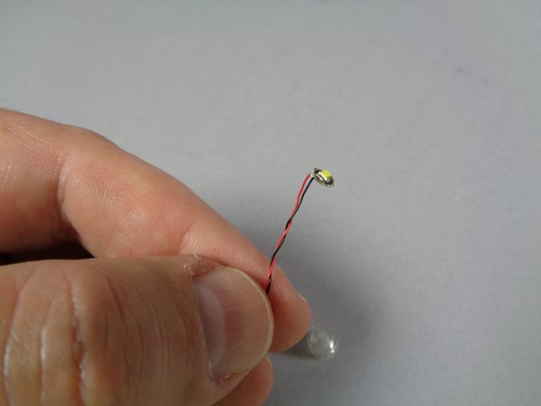
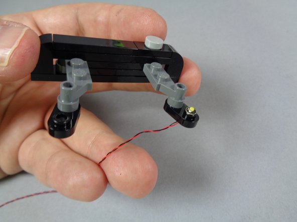
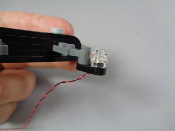
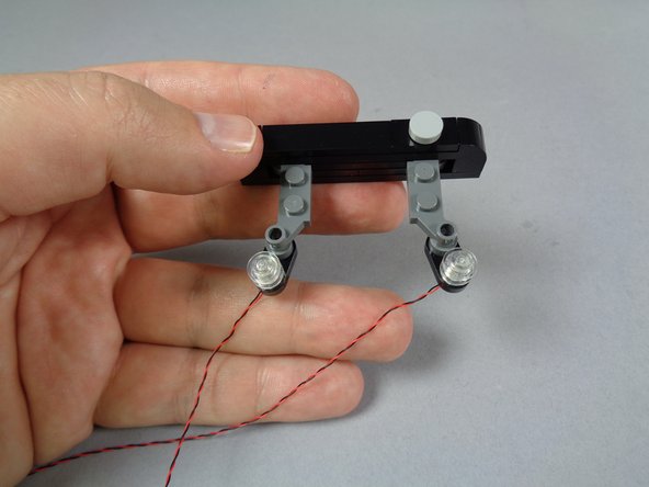
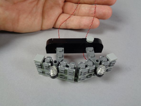
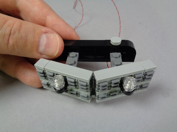
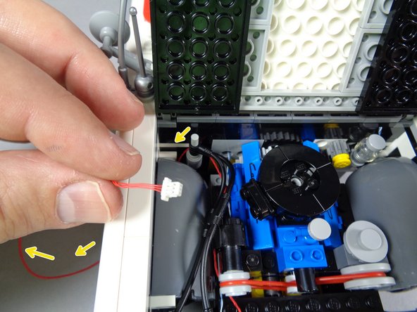
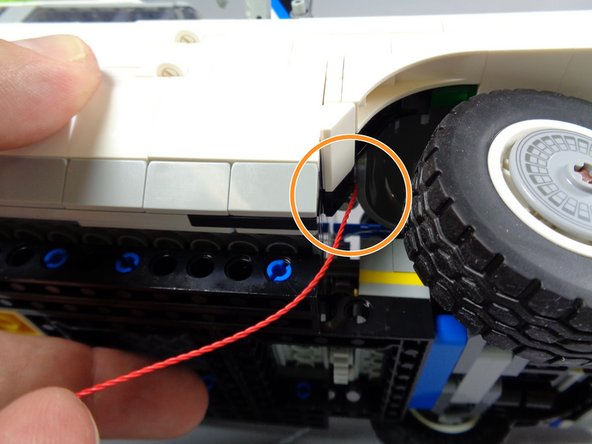
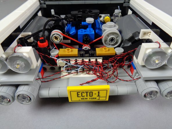
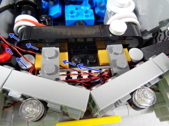
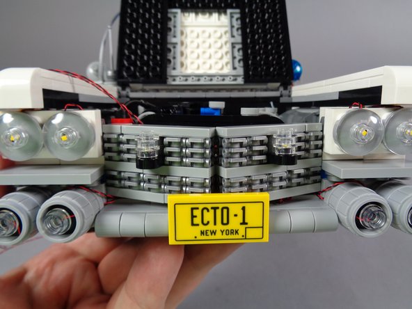
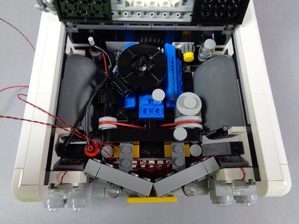
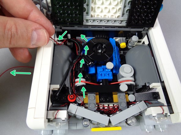
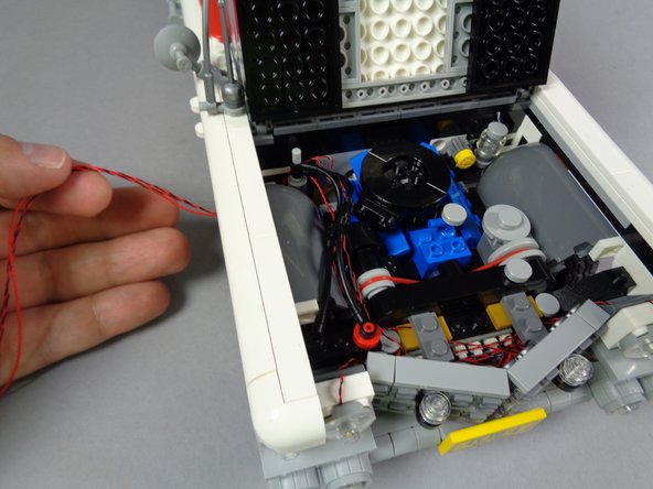
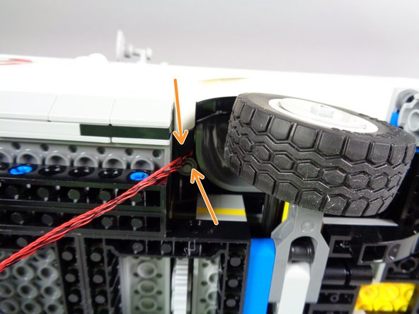
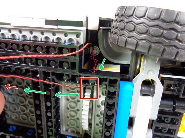
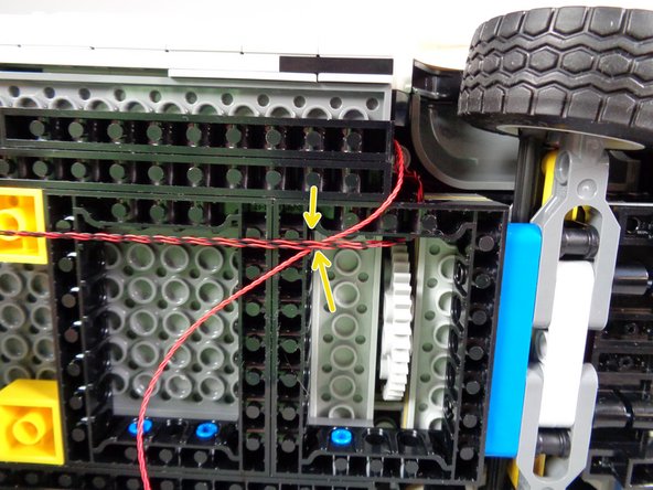
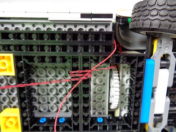
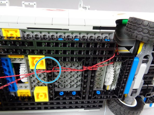
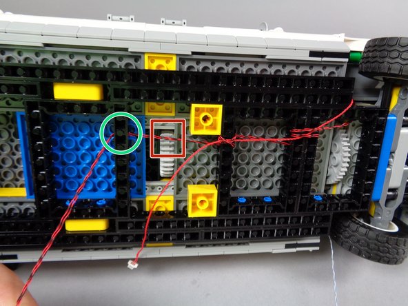
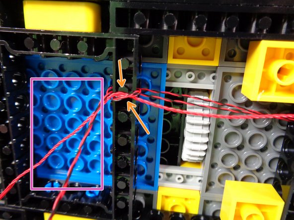
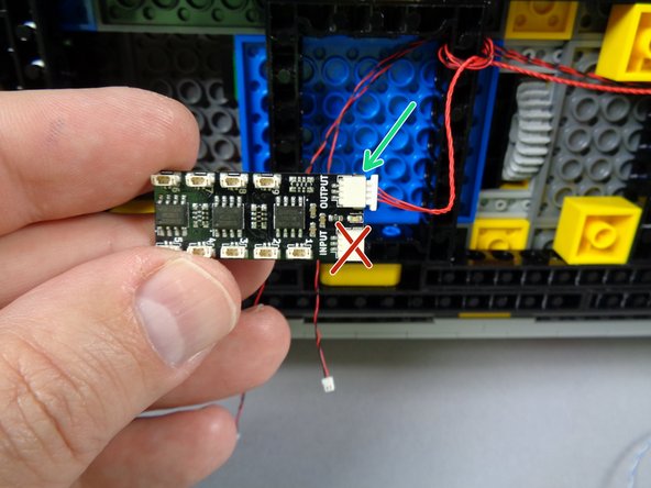
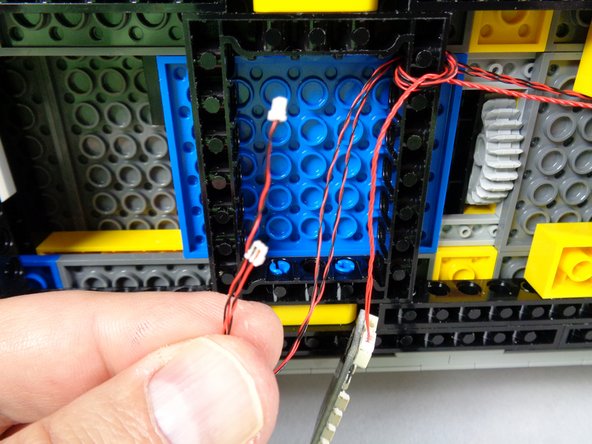
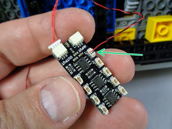
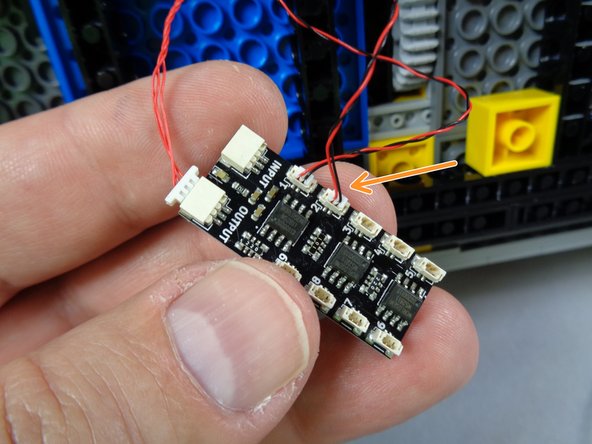
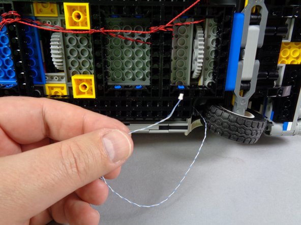
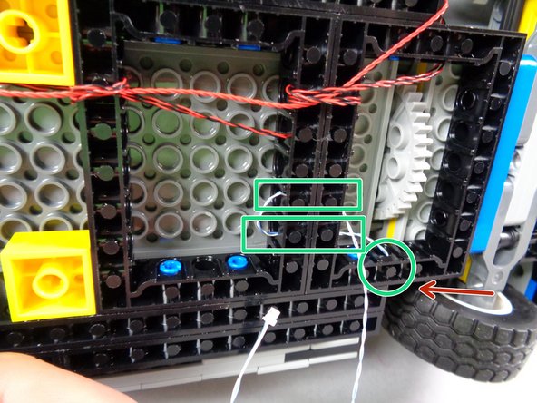
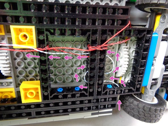
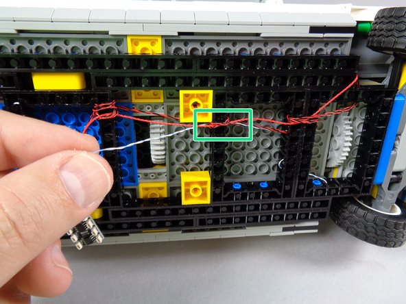
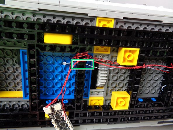
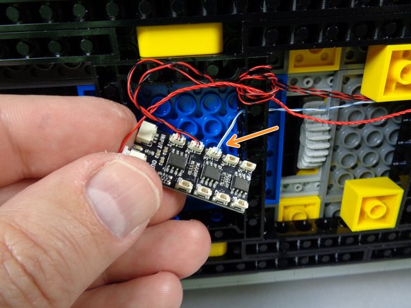
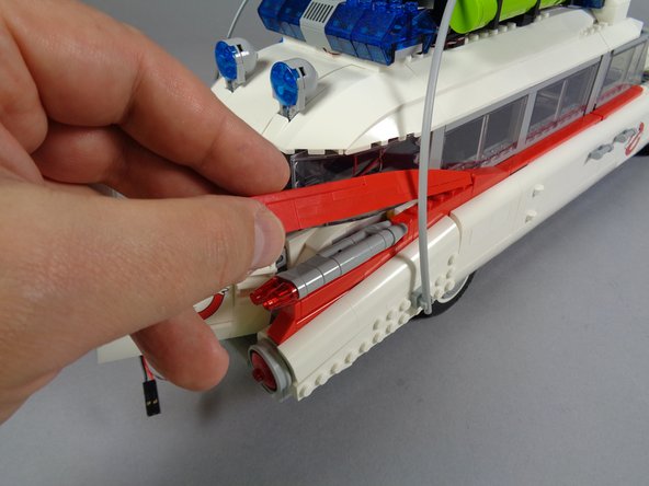
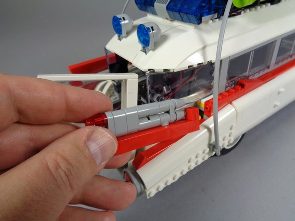
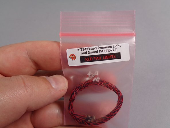
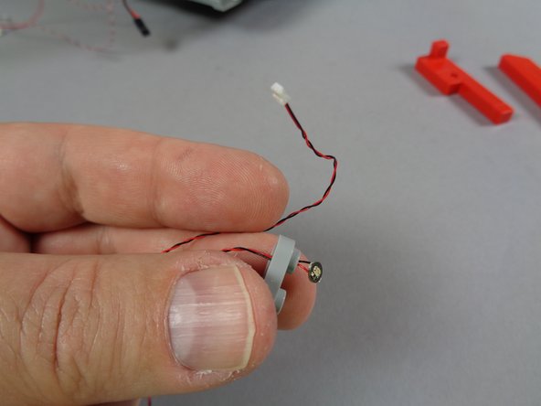
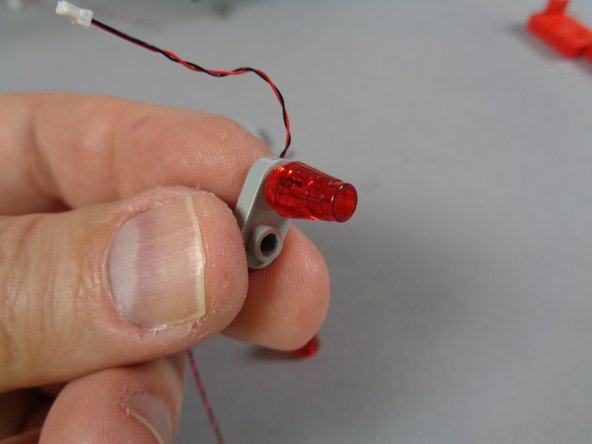
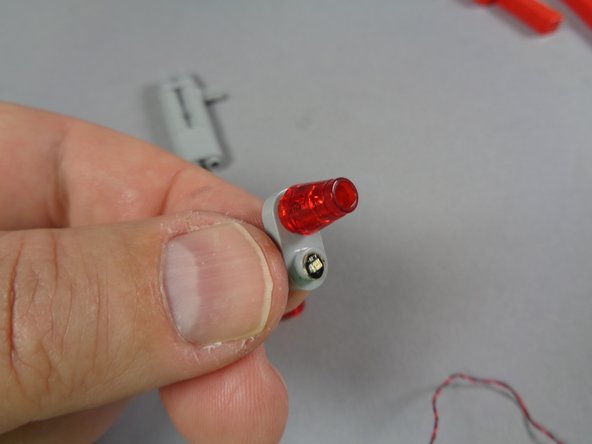
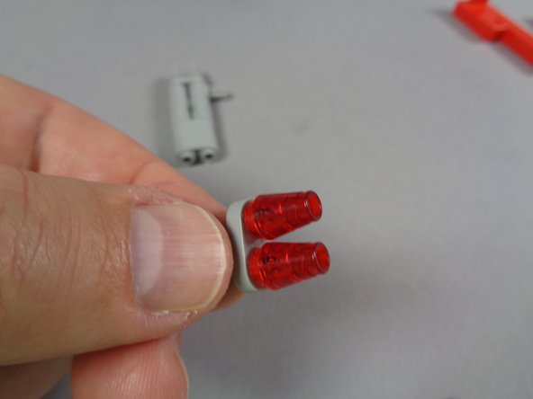
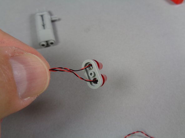
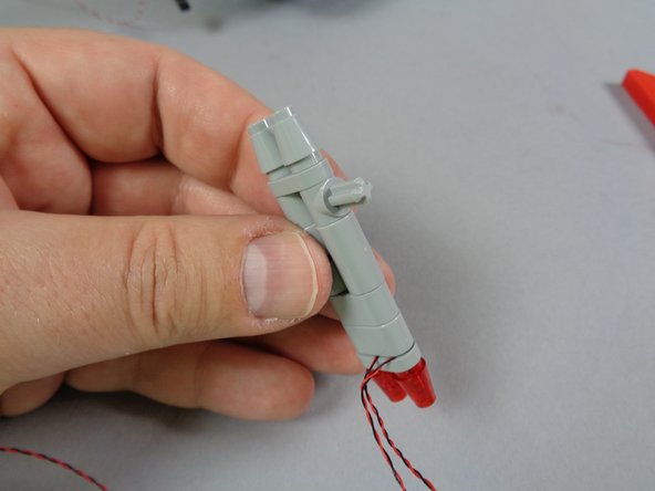
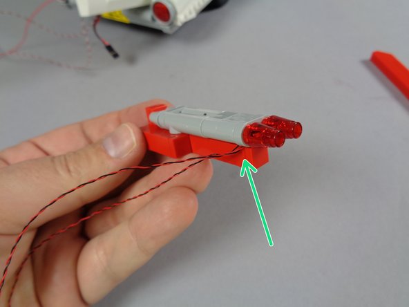
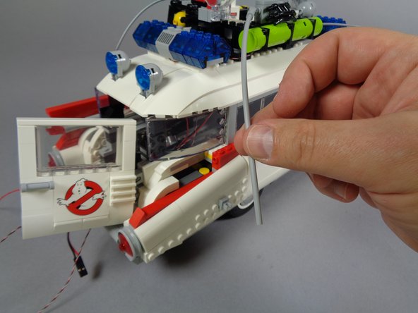
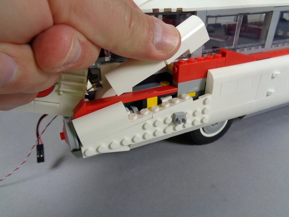
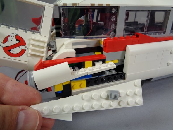
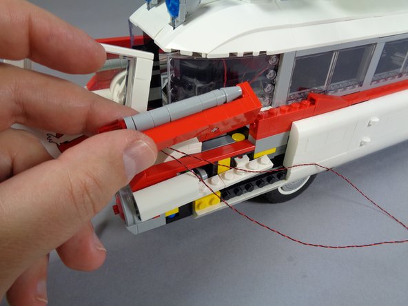
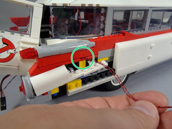
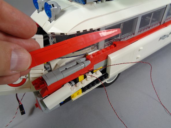
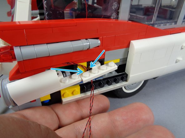
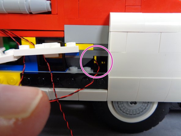
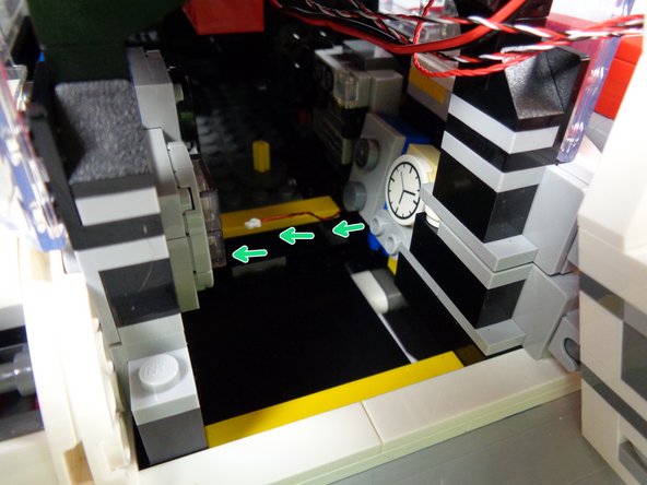
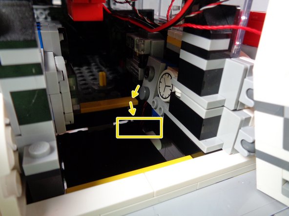
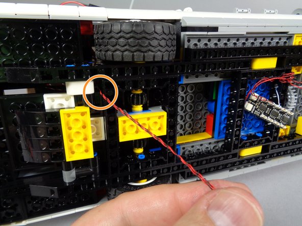
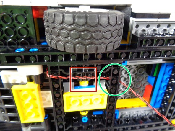
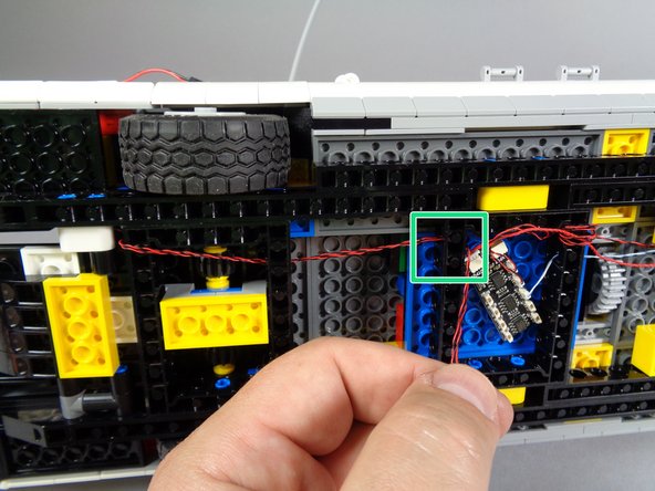
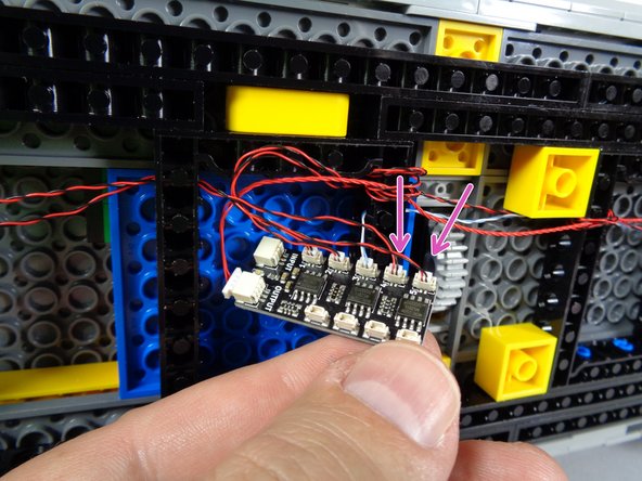
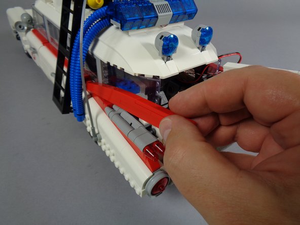
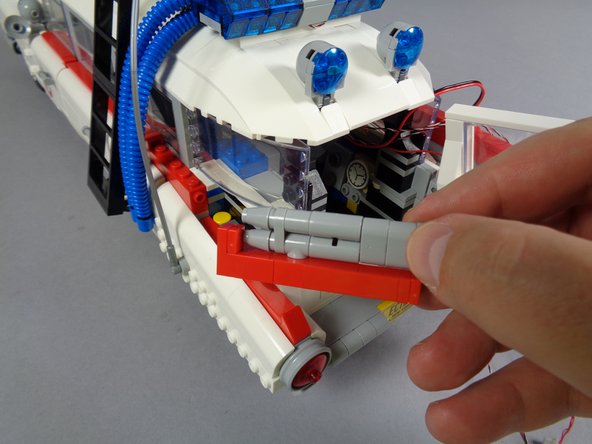
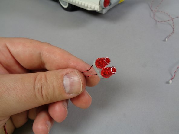
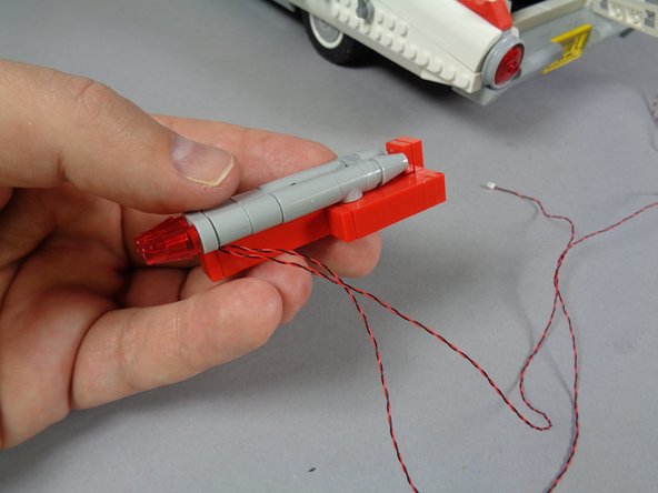
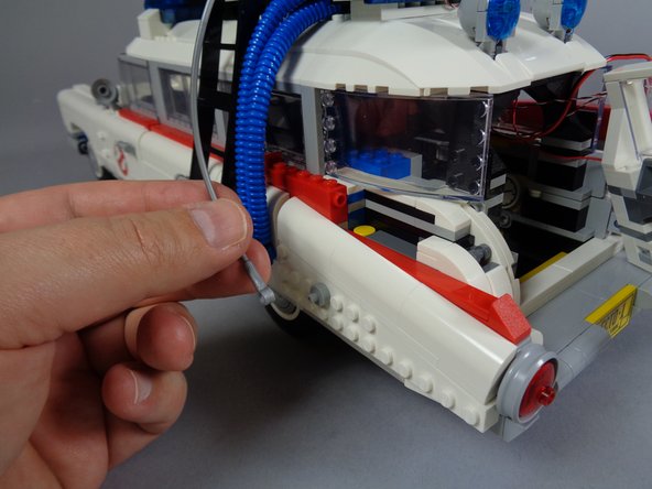
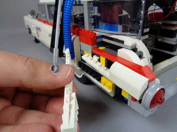
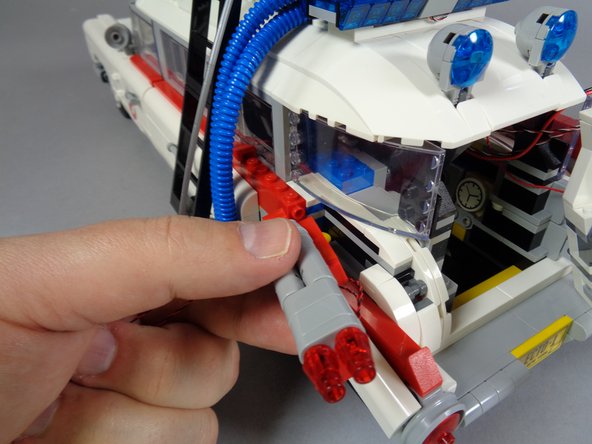
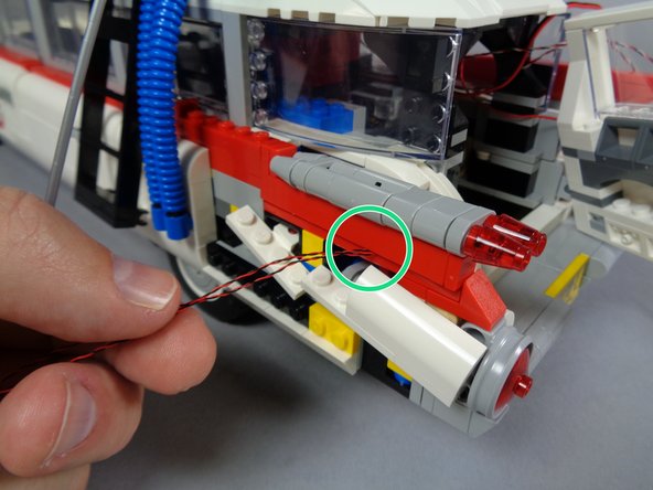
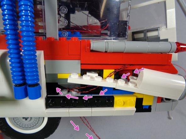
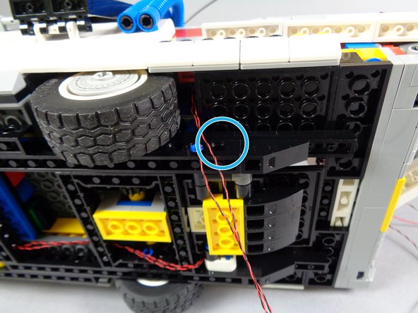
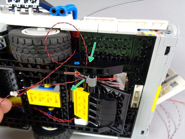
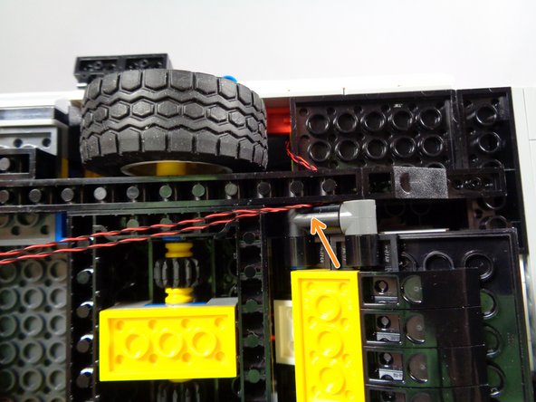
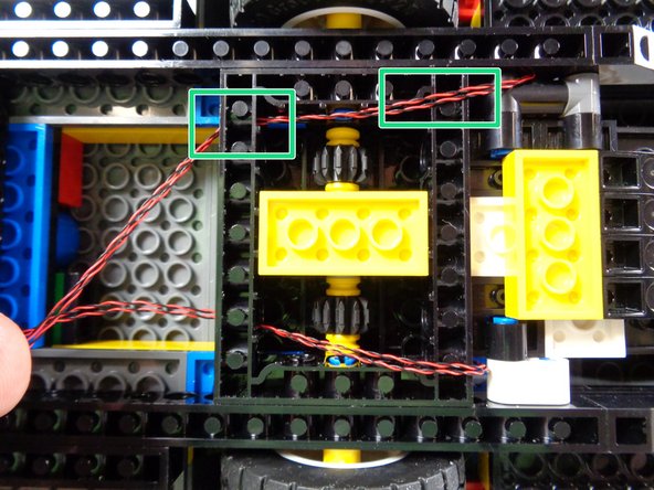
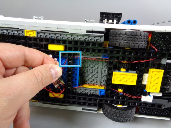
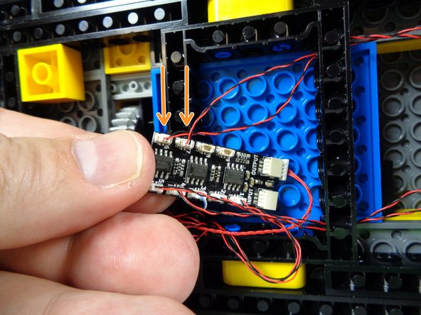
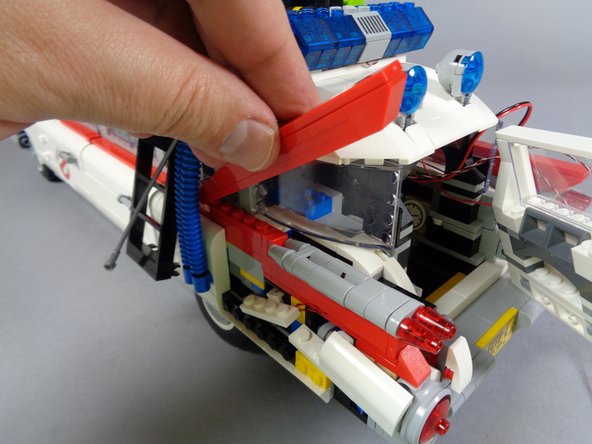
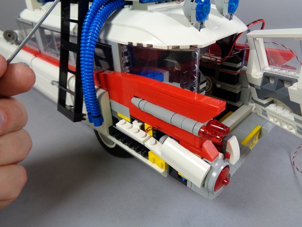
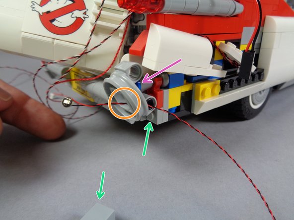
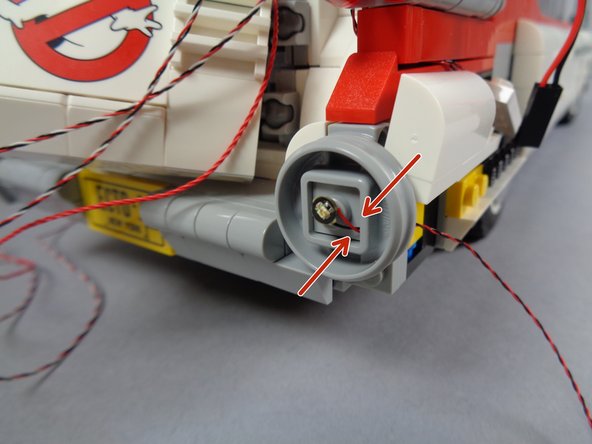
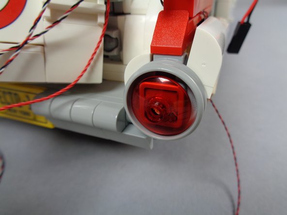
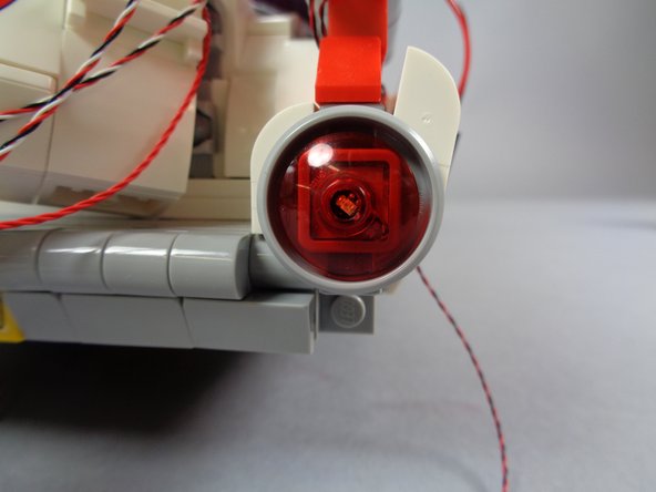
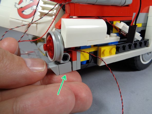
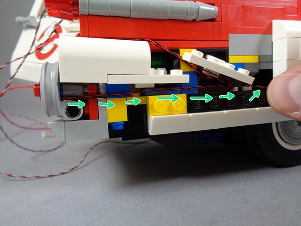
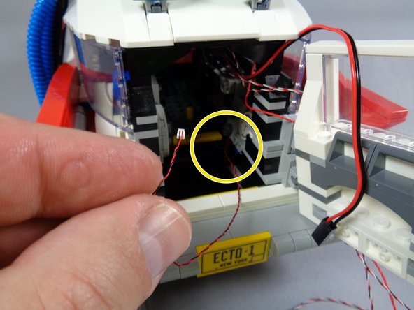
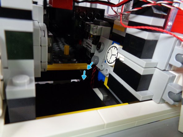
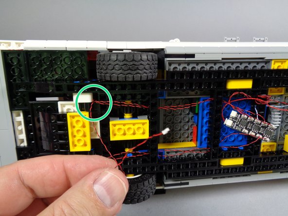
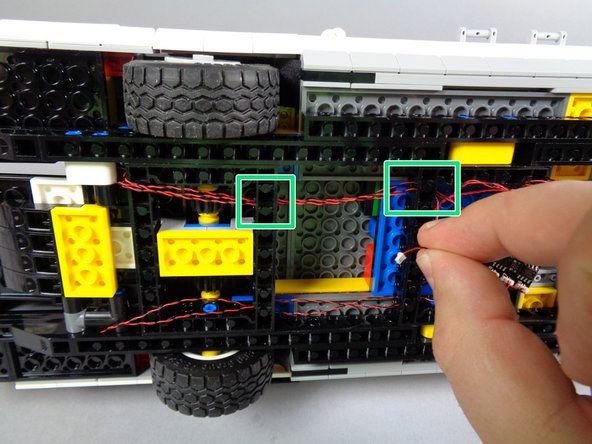
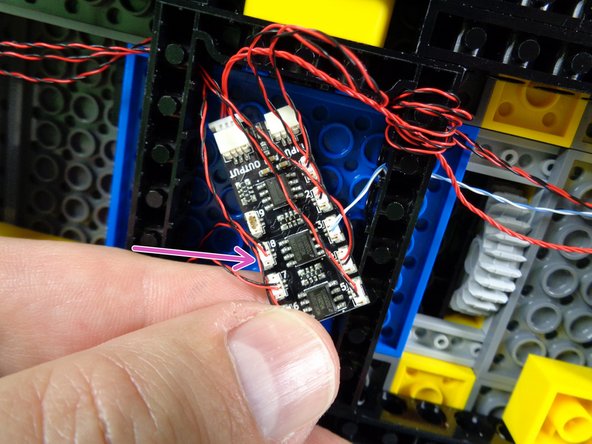
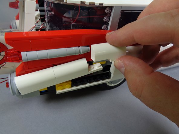
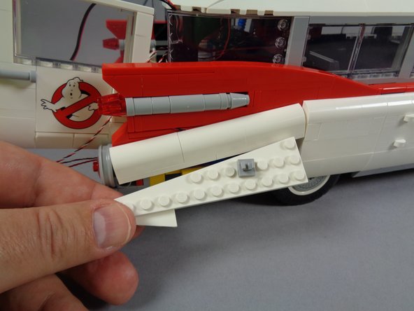
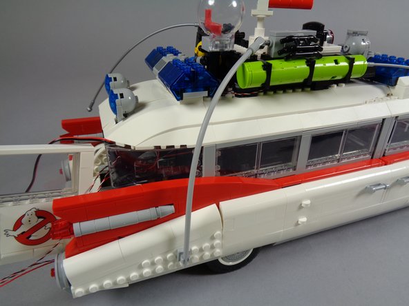
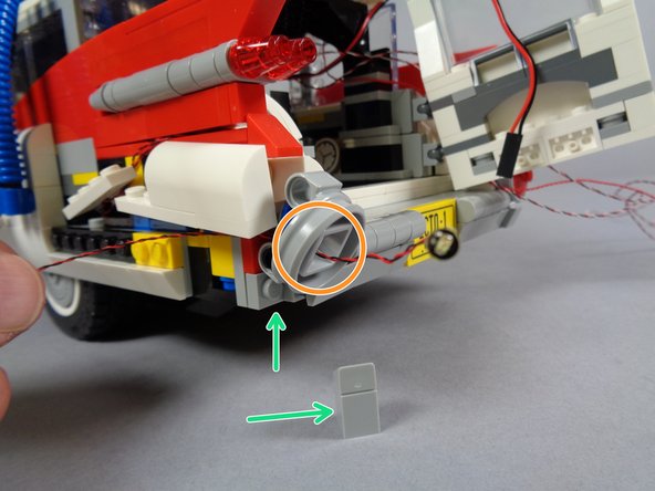
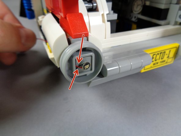
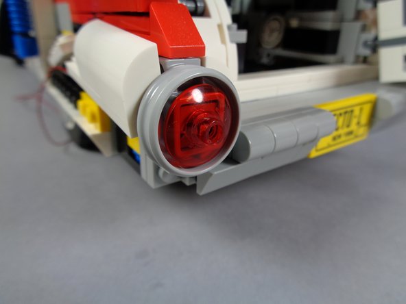
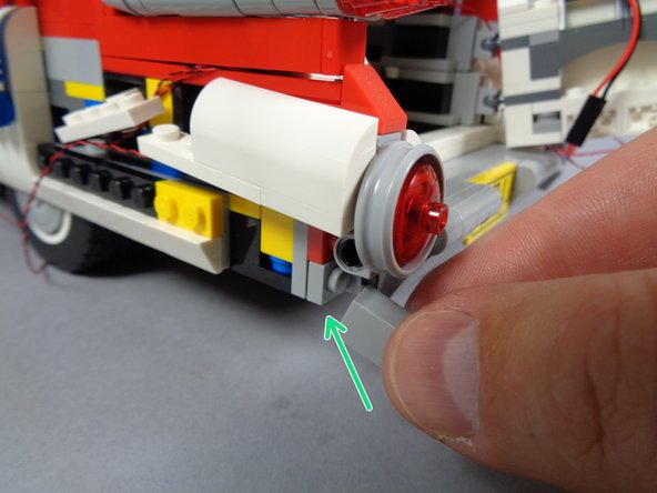
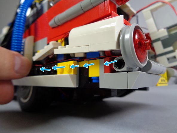
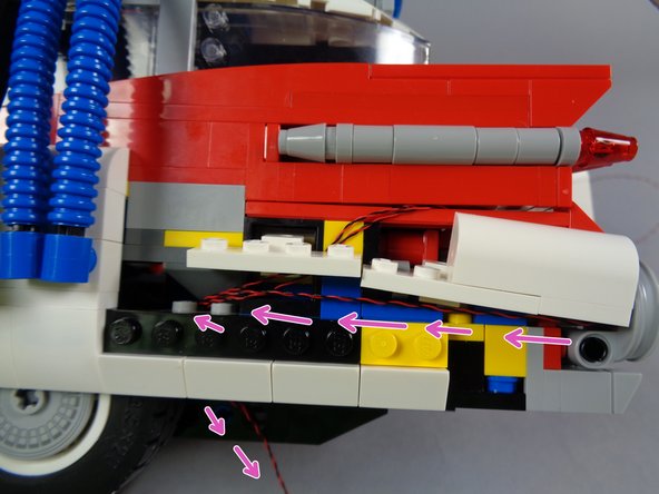
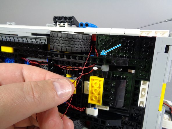
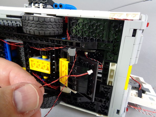
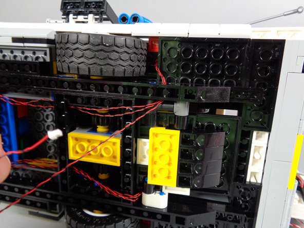
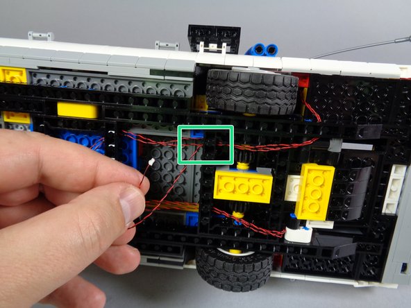
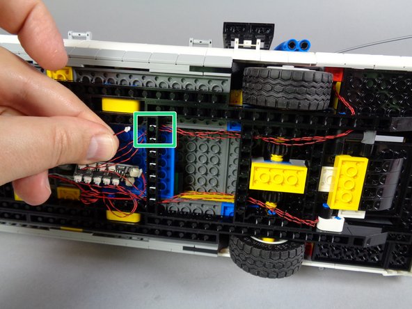
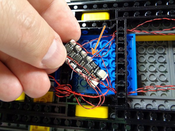
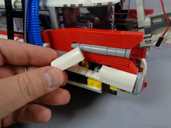
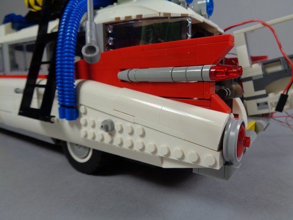
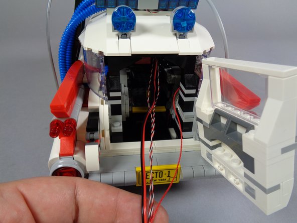
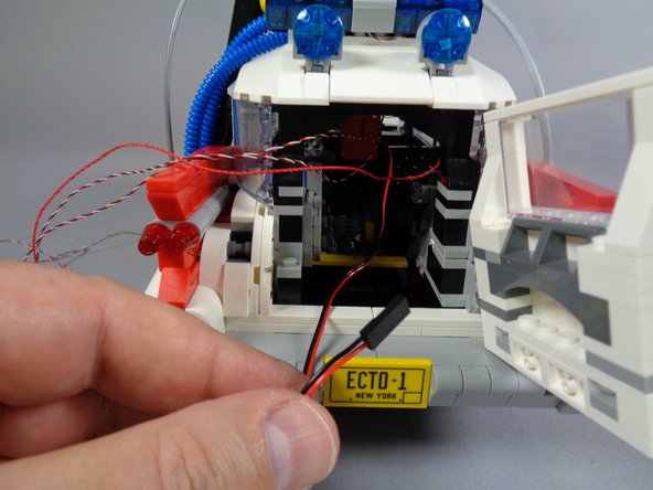
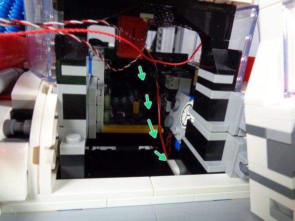
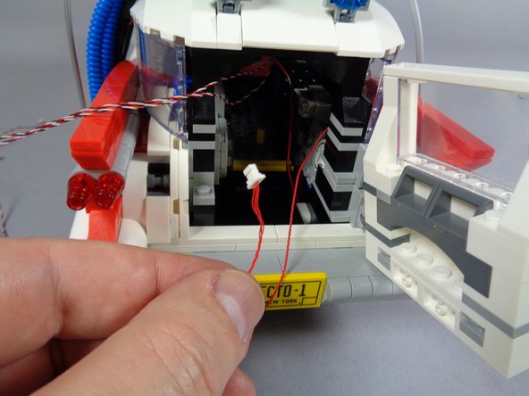
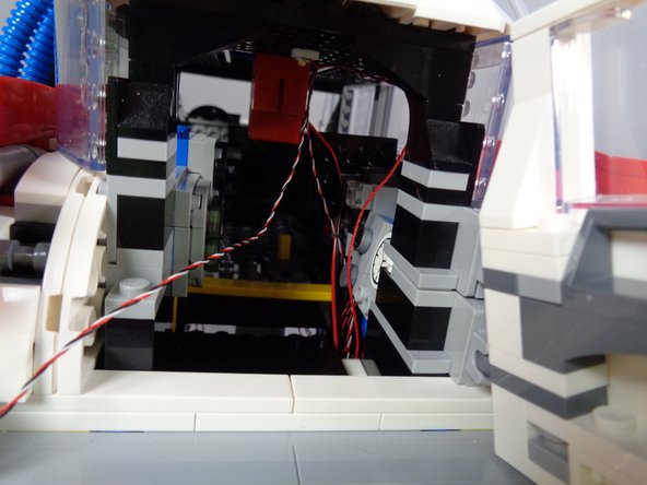
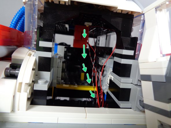
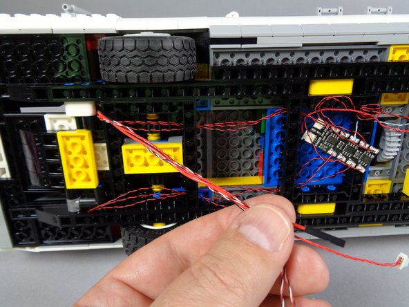
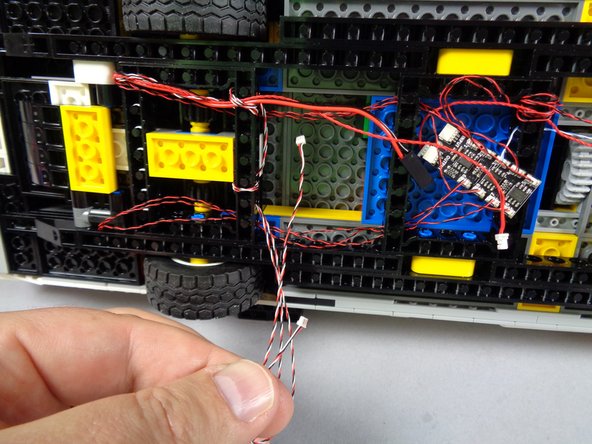
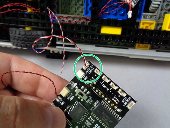
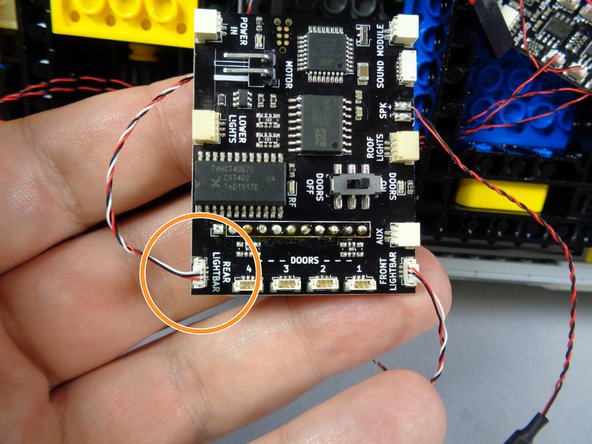
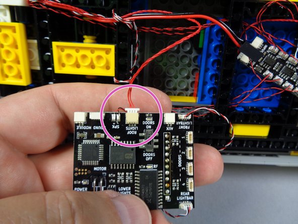
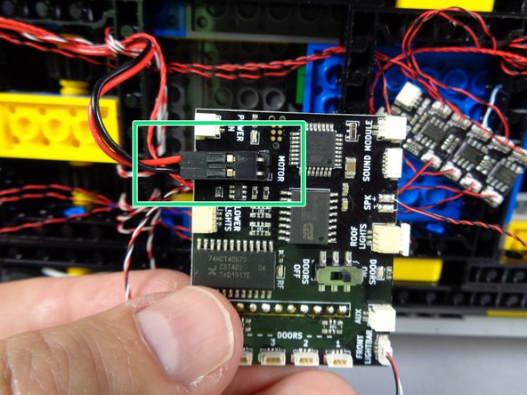
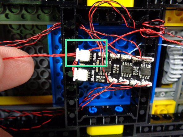
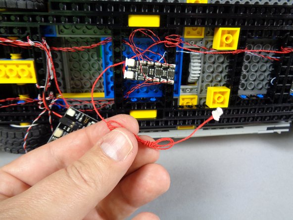
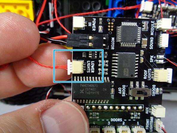
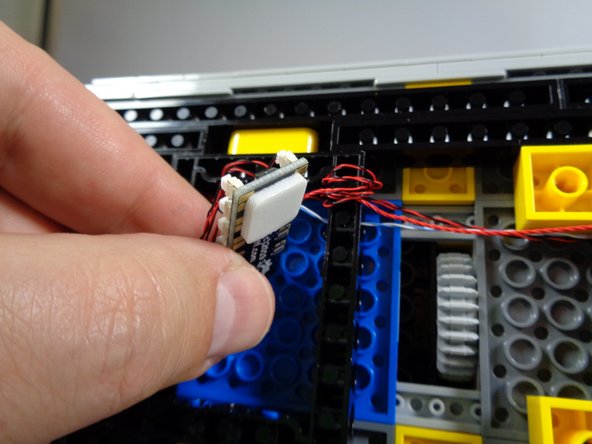
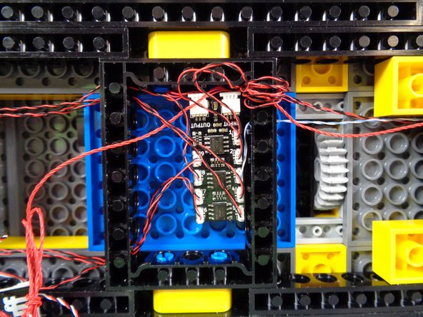
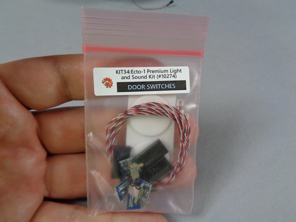
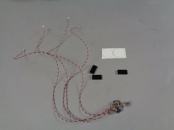
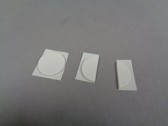
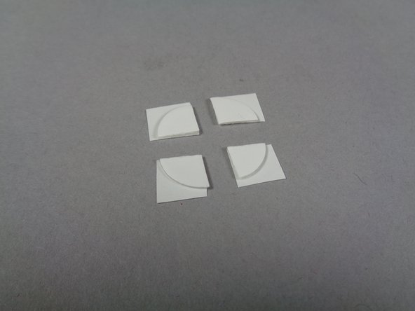
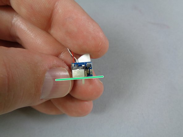
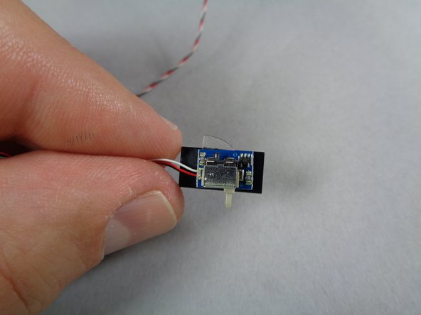
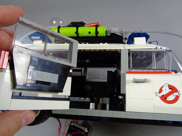
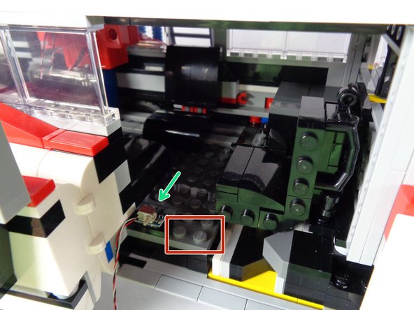
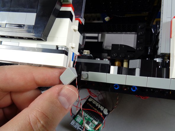
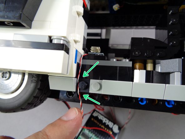
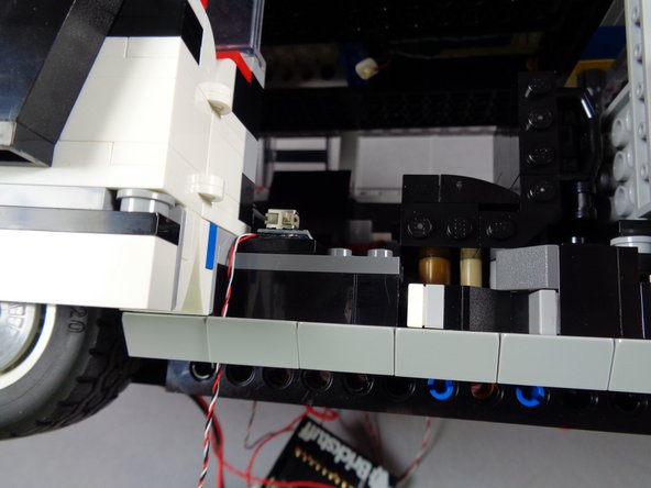
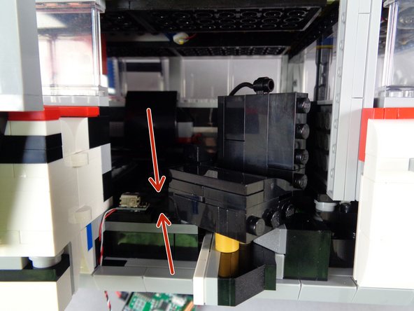
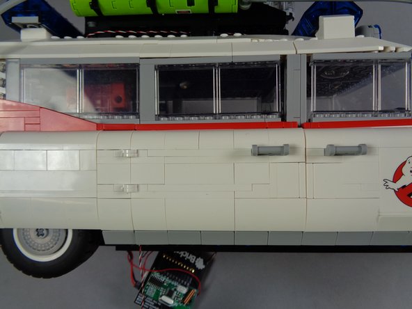
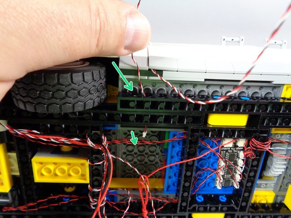
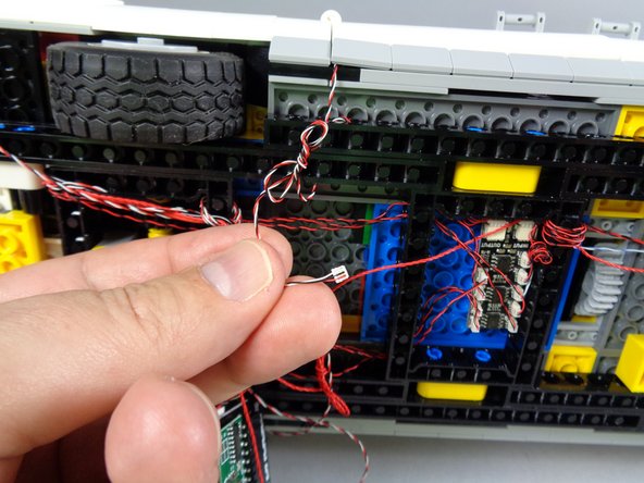
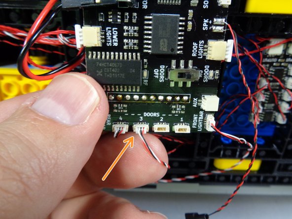
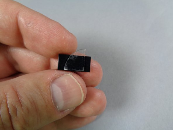
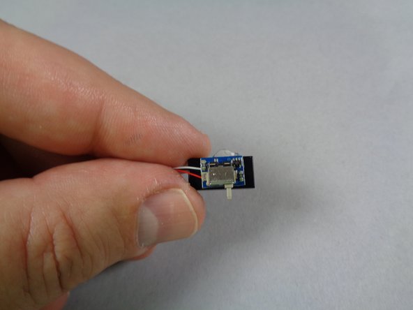
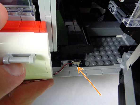
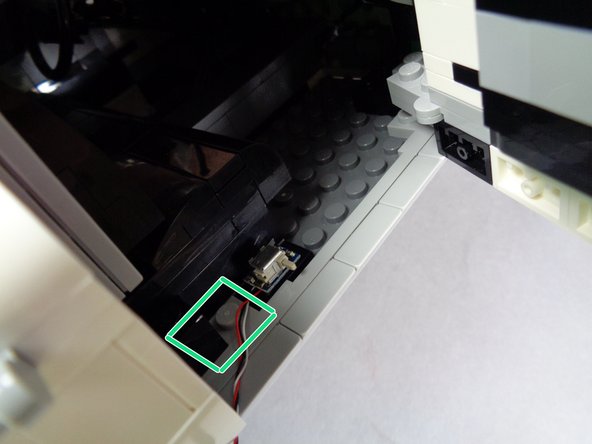
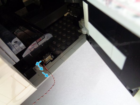
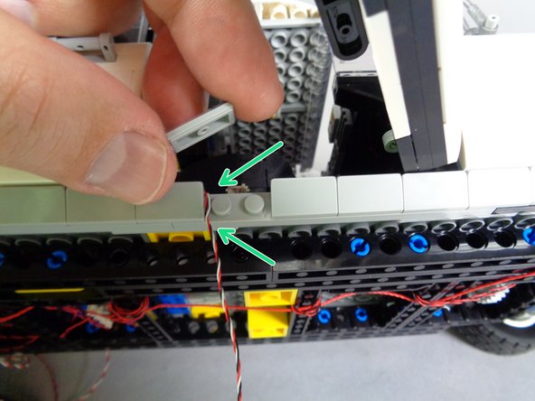
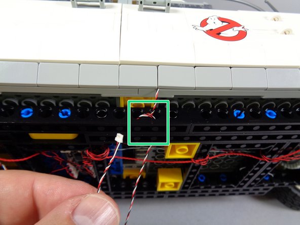
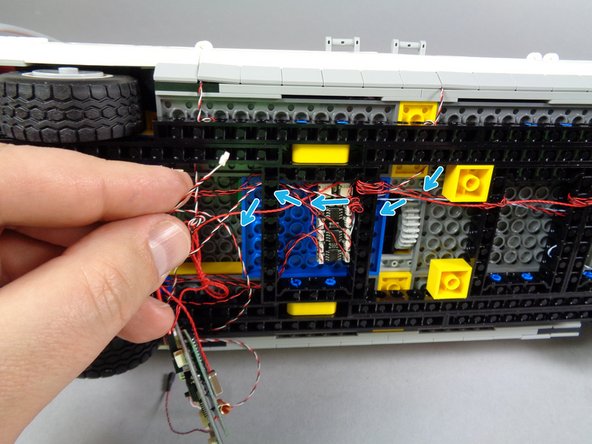
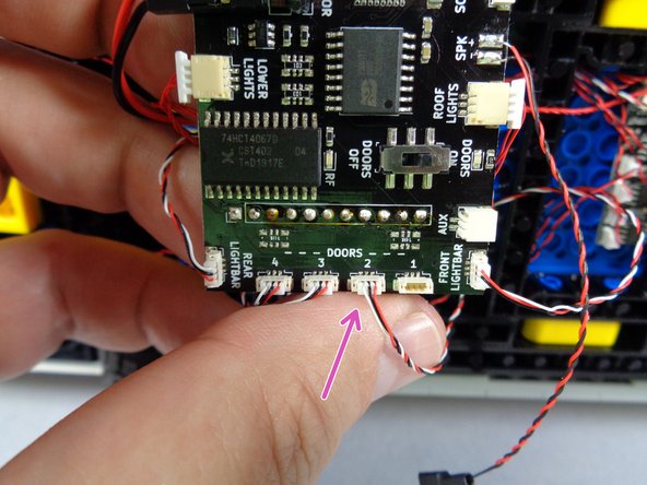
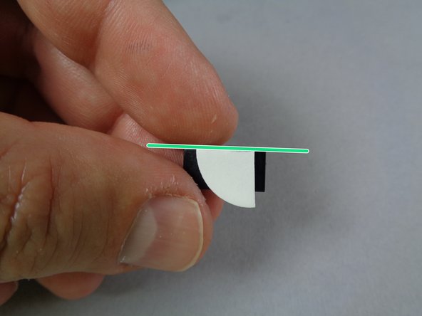
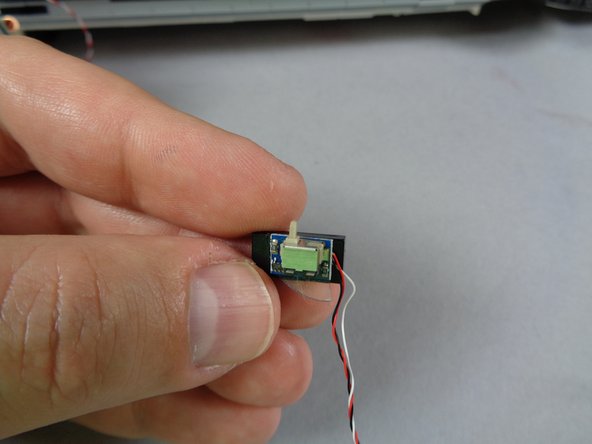
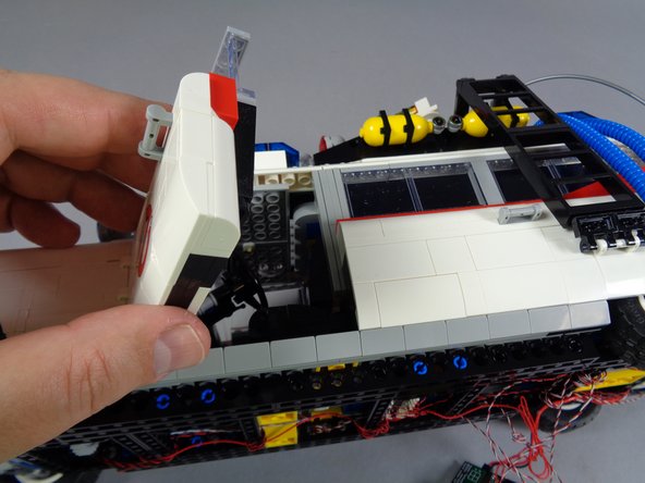
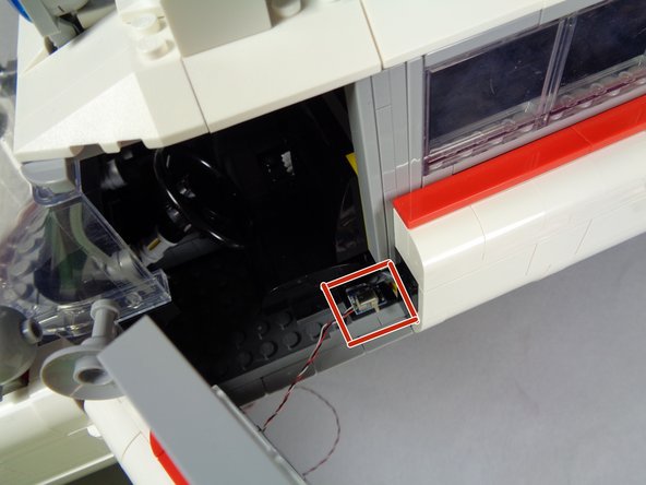
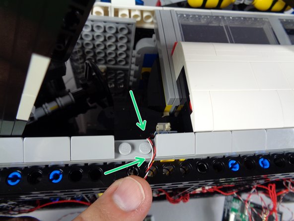
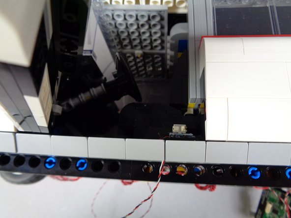
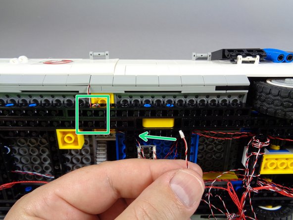
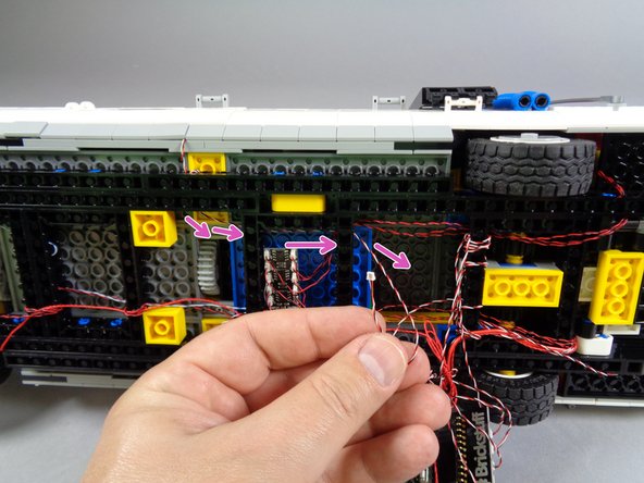
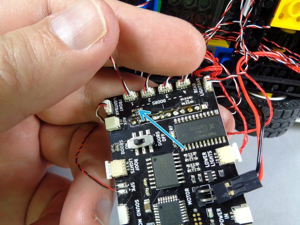
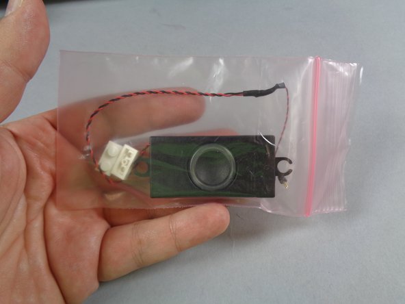
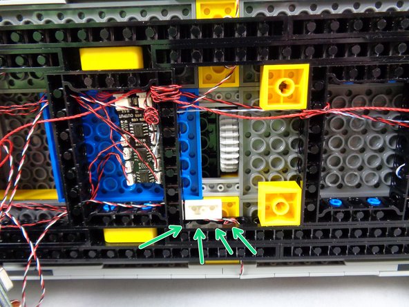
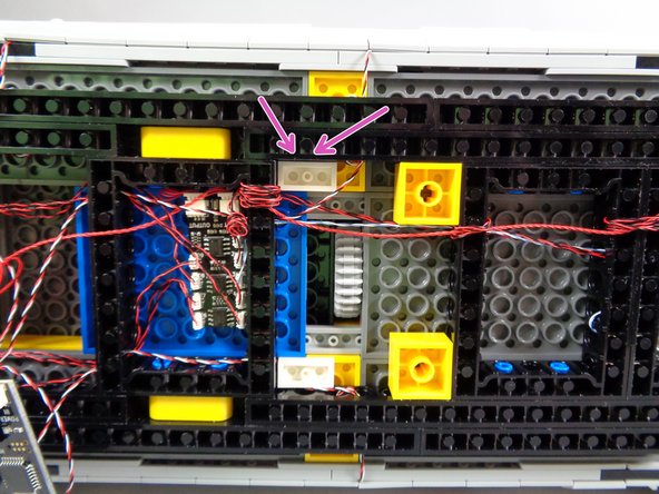
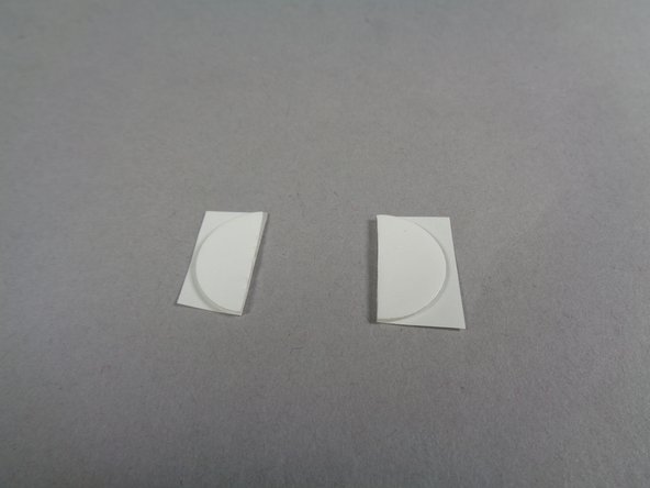
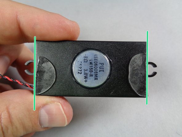
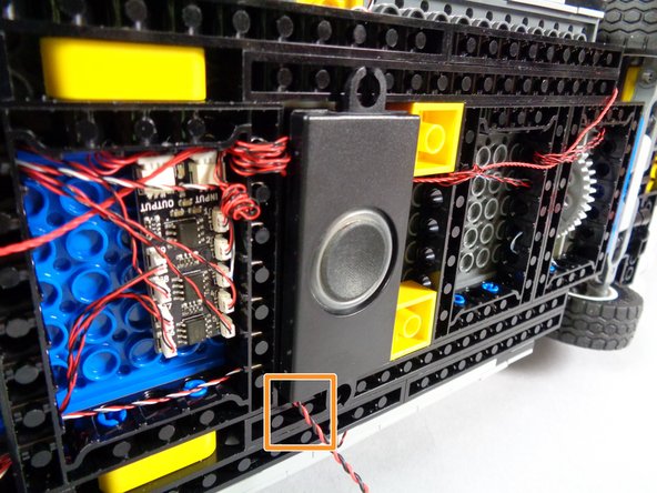
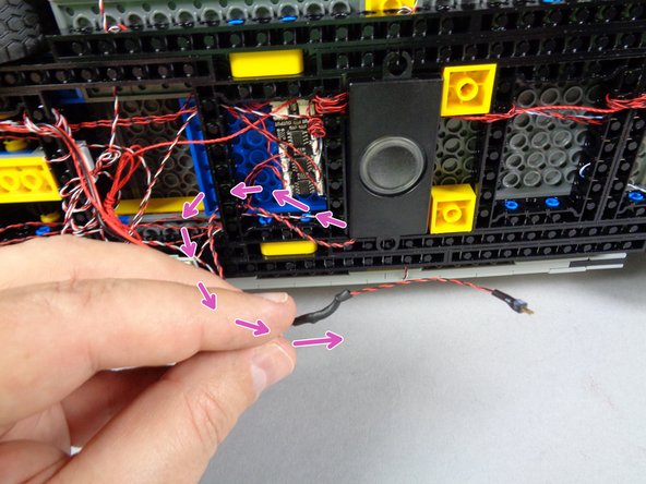
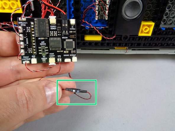
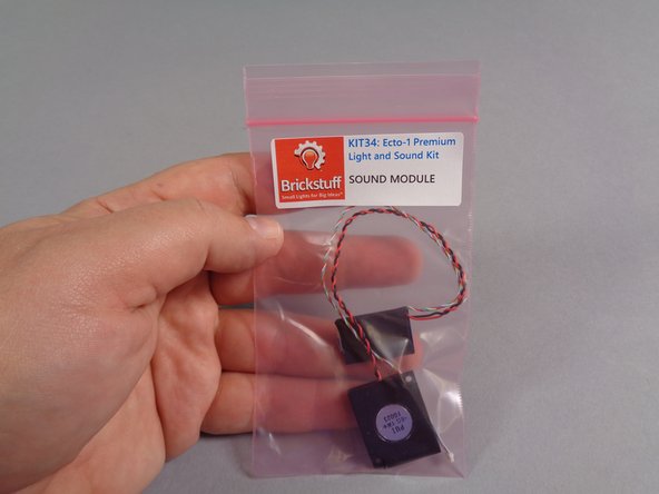
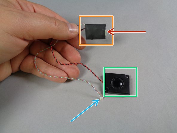
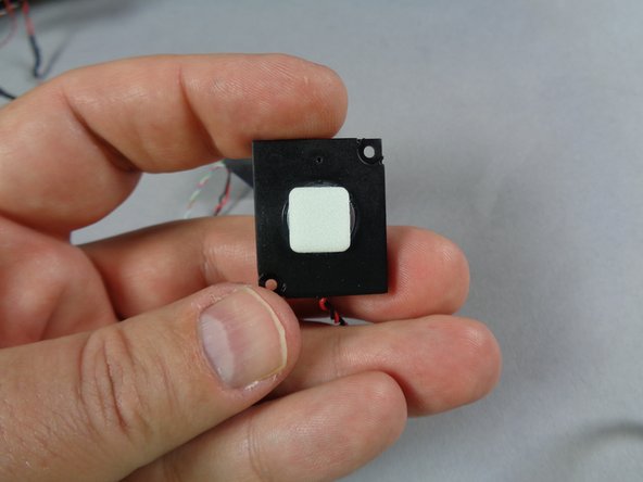
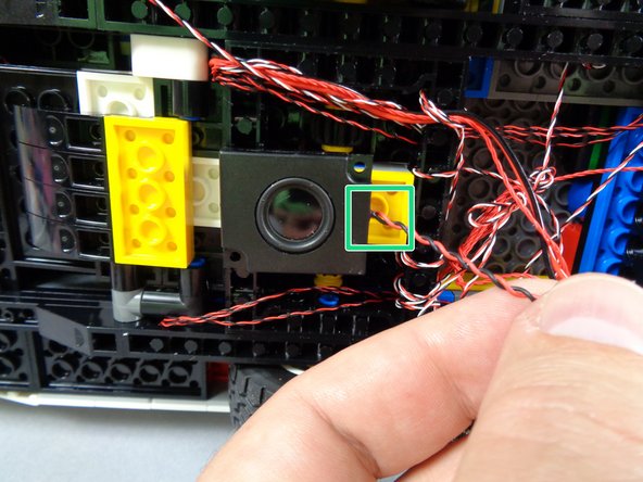

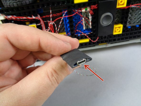
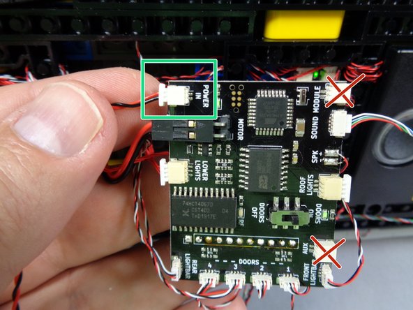
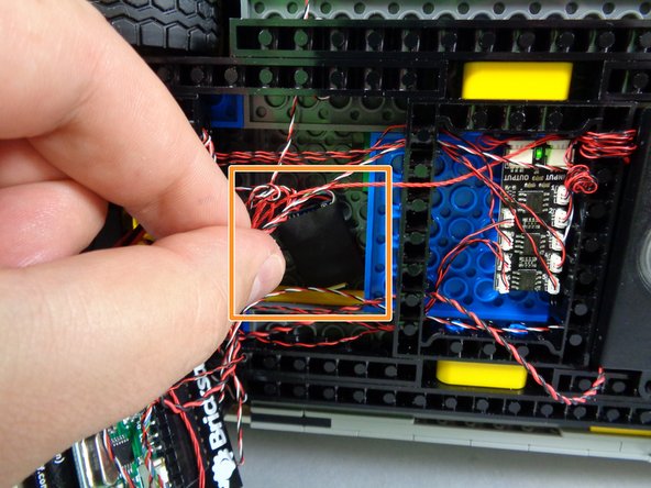
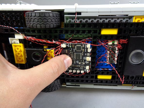
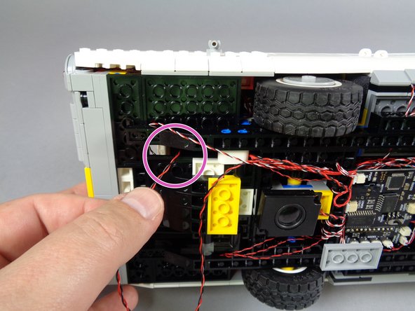
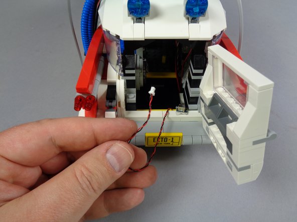
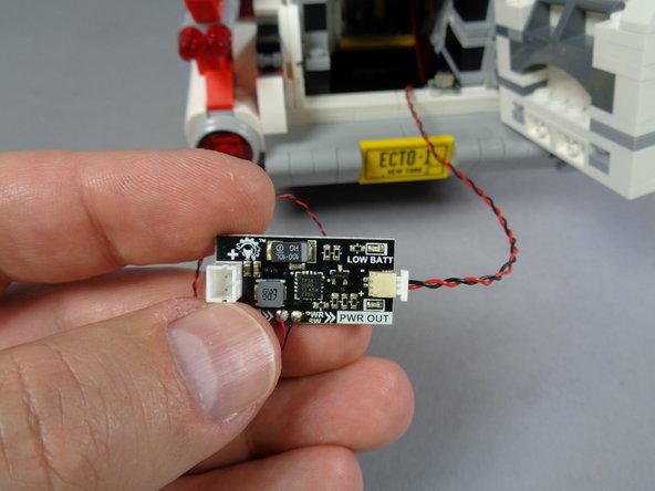
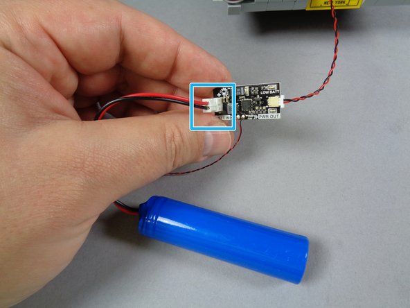
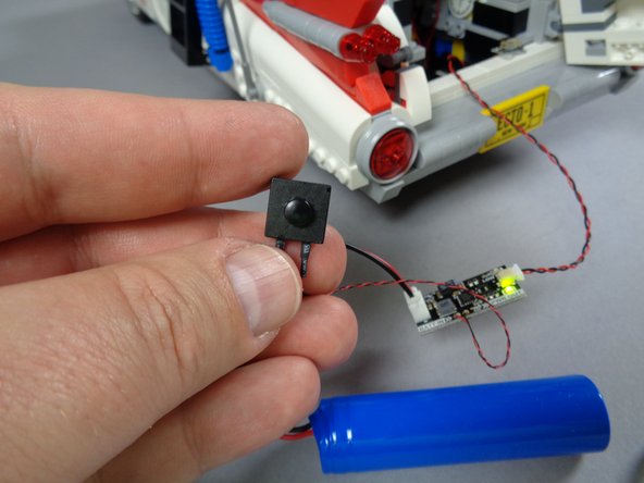
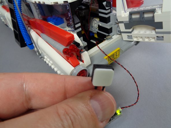
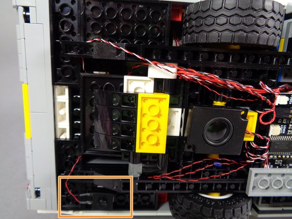
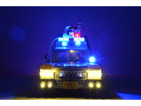
Attached Documents
