Tools
Parts
-
-
There are several ways to read this guide:
-
Reading it on the web in your browser.
-
Downloading a PDF copy of the guide. You can do this by selecting "Download PDF" as shown by the red rectangle in the first photo. Click on the Options heading in the upper right corner of the screen (see the green rectangle).
-
In the "Dozuki" application, which is available for download from the Apple App Store and various Android and Google marketplaces.
-
New line.If you view this guide in the Dozuki app, search for "Brickstuff" the first time you open the app, then select "Product Guides" from the categories listed under Brickstuff. Scroll down to find this guide.
-
You can also translate this guide into another language when viewing on the web. To do this, install a translator extension into your browser and use that extension/plug-in to translate the page. Using the main Google translate website (translate.google.com) does not work.
-
-
-
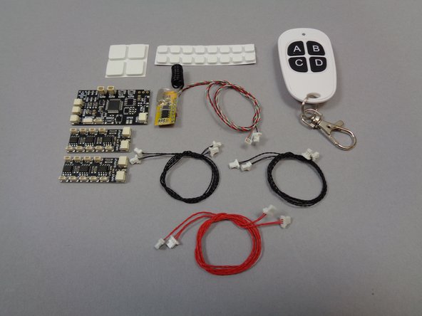
This kit includes two types of controller/adapter boards:
-
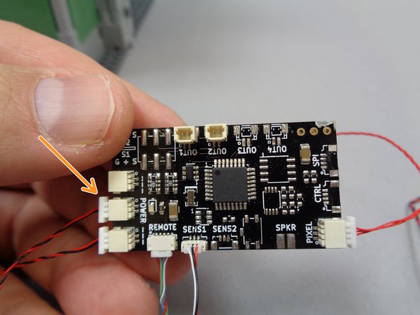
TRUNK08 master controller (see first photo). This is the main controller that manages all of the light and sound effects in the kit.
-
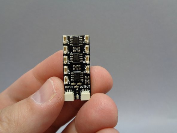
BRANCH09X adapter boards (your kit contains two of these, see the second photo). These are the boards to which the lights connect. Each board has nine connectors numbered 1-9. For the lights to work properly, you must pay close attention to which plug each light connects. These boards also have one large INPUT plug and one large OUTPUT plug.
-
Here are some very important tips to keep in mind as you connect the parts in this kit:
-
Plugs connect to adapter boards and controllers only one way. Do not force plugs.
-
Do not remove plugs with tabs by pulling on the wire. Always use your fingernails or tweezers to remove plugs by pulling on the tabs of the plug, not the wires.
-
Many boards have connectors that face vertically (upward). Use extra care when connecting or disconnecting plugs to these connectors. Pulling or pushing sideways on any vertically-facing plug can cause the plug to come detached from its circuit board.
-
-
-
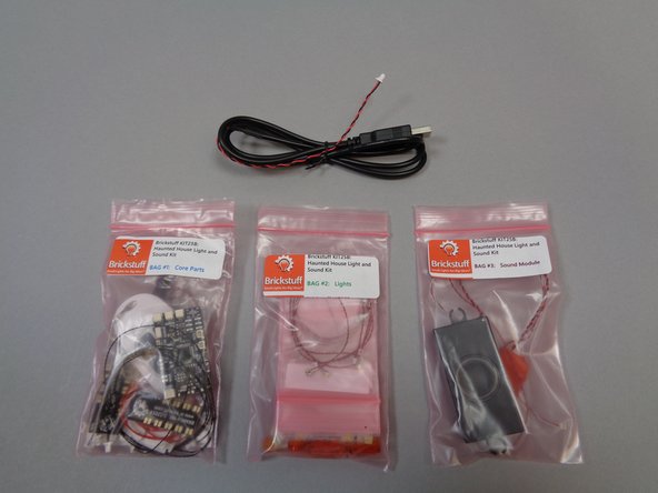
The photos for this step show the parts included with your kit. As shown in the first photo, there are three main bags and one USB cable.
-
You can use any standard iPhone or iPad type charger to power the USB cable, or any USB battery bank. We also sell our own mains adapter with global voltage and plug support on our website.
-
The second photo shows the contents of Bag 1 (labeled "Core Parts).
-
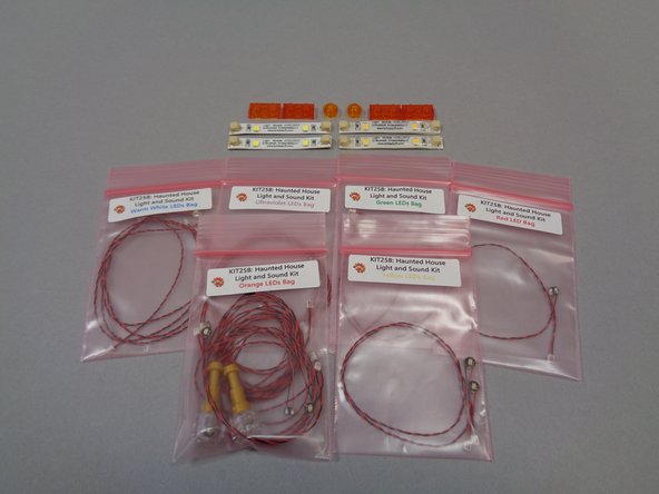
The third photo shows the contents of Bag 2 (labeled "Lights"). There are six smaller bags inside Bag 2, each with a different color Pico LED light. Bag 2 also contains four light strips (two warm white and two cool white) and six transparent LEGO® plates for use with the fireplace.
-
Because most of the Pico LEDs look similar despite having different colored lights, you should keep the lights in their own bag until needed to install.
-
Bag 3 contains the sound module with pre-loaded sounds specific to this kit.
-
-
-
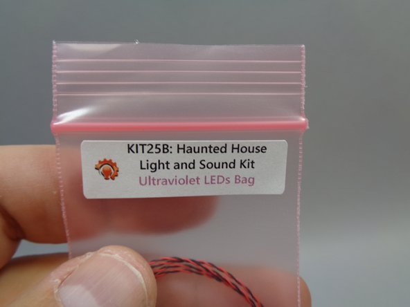
Your kit includes two ultraviolet lights that can be used to make the two ghosts in the Haunted House glow in the dark.
-
These instructions show how to mount the ultraviolet lights on the front roof of the house. You can mount the two ultraviolet lights anywhere within 12" (30.4cm) of the second floor of the house.
-
As shown in the coming steps, the two ultraviolet lights must be connected to plugs #8 and #9 of the BRANCH09X adapter board in order to operate. Keep this in mind if you choose to mount the ghosts in another location.
-
You can also choose not to mount the ultraviolet lights. In this case, just leave them disconnected from the BRANCH09X adapter board. The rest of your kit will operate normally.
-
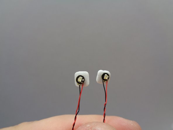
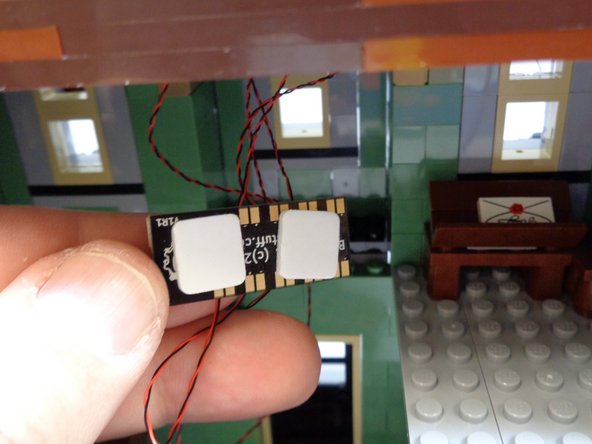
As shown in the first photo, take the small "Ultraviolet LEDs Bag" out of Bag 2 and attach two small sticky squares to the back of the lights as shown in the second photo. The sticky squares are inside Bag 1.
-
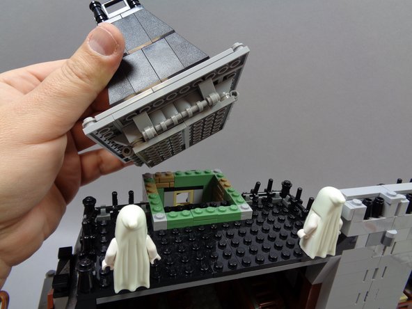
As shown in the third photo, carefully remove the top of the cupola on the haunted House roof.
-
-
-
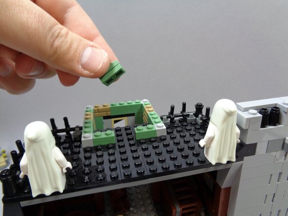
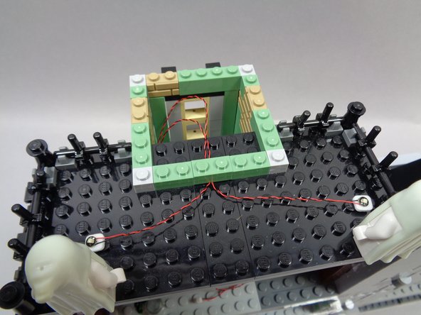
As shown in the photos for this step, remove the center rear section of the cupola wall (two sand green 1x2 plates as shown in the first photo).
-
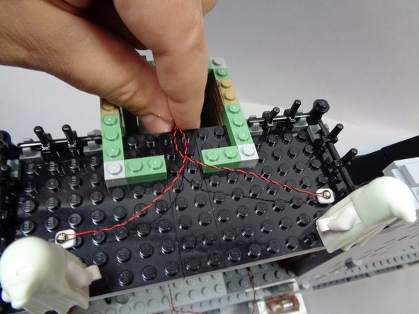
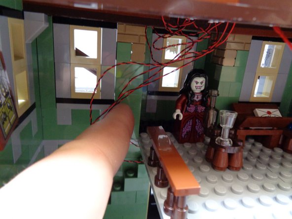
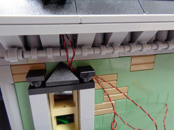
As shown in the second photo, stick the ultraviolet lights in front of the ghosts and run the light wires toward the center of the roof and down into the opening under the cupola.
-
Make sure the light wires run BETWEEN the studs on the roof top, not on top of any studs. Wires can become pinched or damaged if you place LEGO® parts on top of them if they run on top of studs.
-
As shown in the third photo, re-attach the pieces you removed earlier. This should secure the two ultraviolet light wires in place.
-
-
-
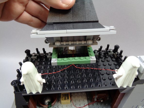
As shown in the first and second photos, re-attach the cupola. the ultraviolet light wires should now pass into the open area under the cupola.
-
As shown in the third photo, carefully remove the large section of attic floor.
-
-
-
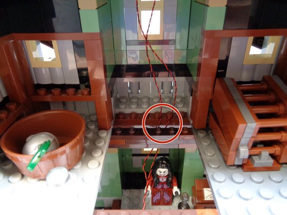
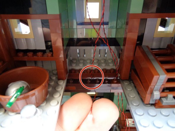
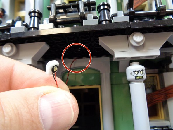
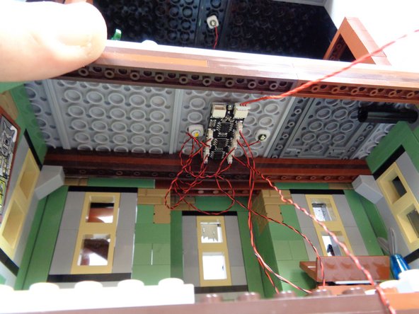
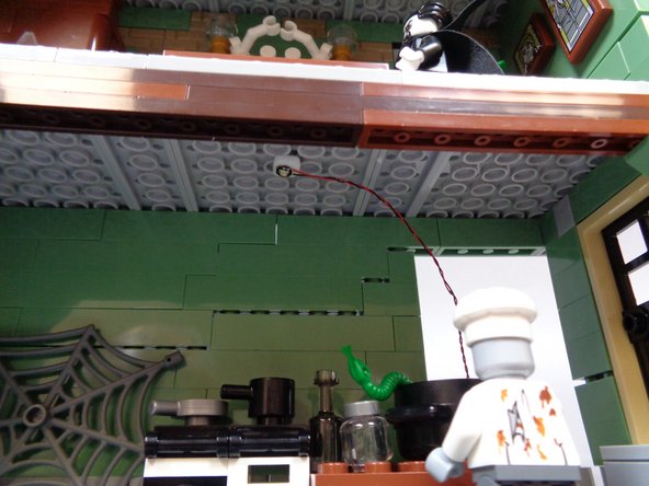
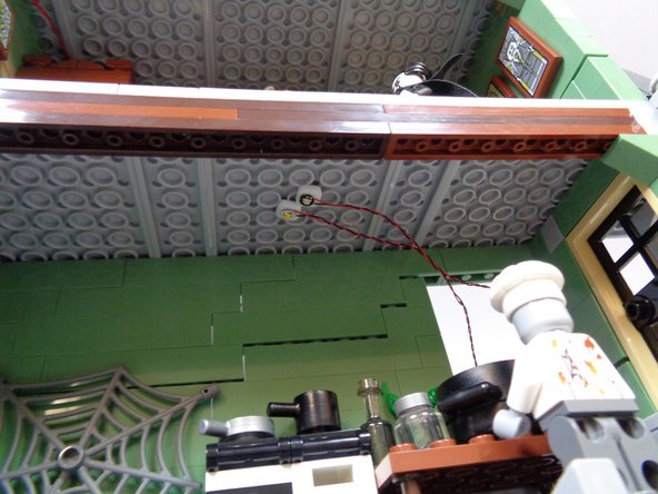
As shown in the first photo, pass the two ultraviolet light wires down through the hole in the attic floor.
-
As shown by the red circle in the first photo, make sure the two wires pass BEHIND the horizontal floor support.
-
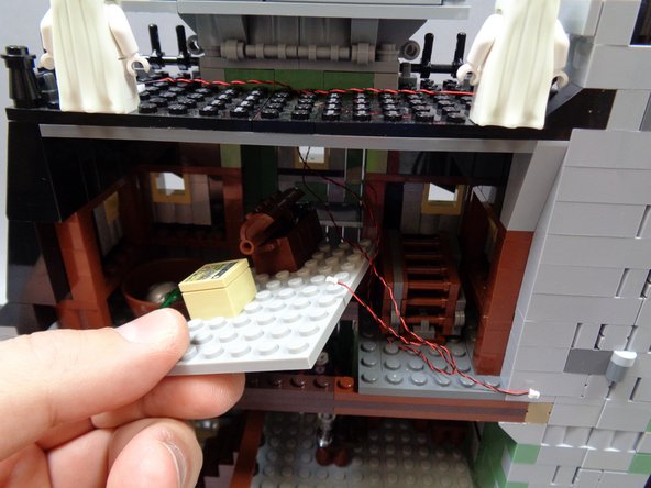
Remove one of the BRANCH09X adapter boards from Bag 1 as shown in the second photo.
-
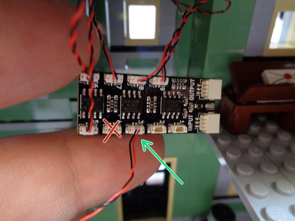
As shown by the green arrows in the third photo, connect the two ultraviolet light wires to plugs #8 and #9 on the BRANCH09X adapter board.
-
It is very important that you connect each light to the exact plug number on each BRANCH09X adapter. If you connect a light to the wrong plug, the lighting effects will not operate as designed.
-
-
-
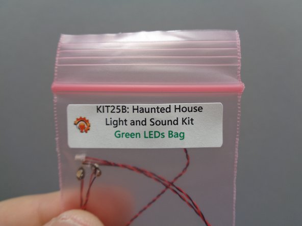
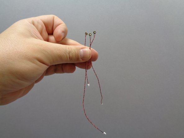
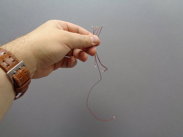
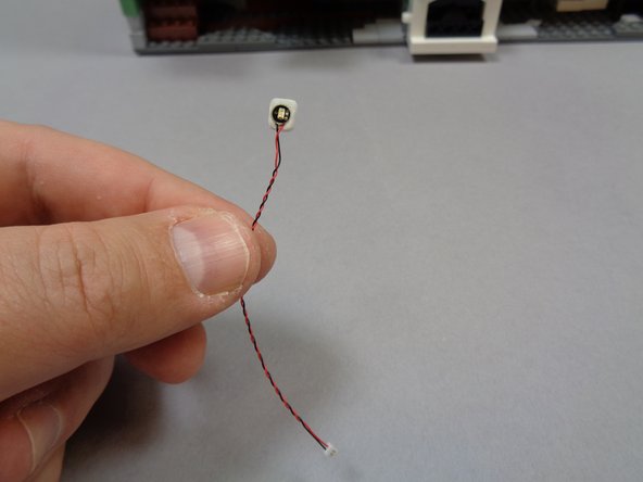
Remove the small "Green LEDs Bag" from Bag 2. Inside will be three green lights with two different wire lengths: one light with a 3" (7.6cm) wire and two lights with 6" (15.2cm) wires.
-
The second photo shows the different lengths of wire for the green lights.
-
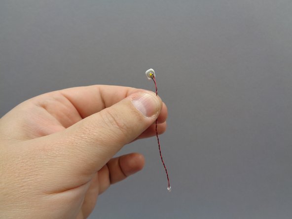
Take one of the green lights with 6" (15.2cm) wires and attach a small sticky square to the back as shown in the third photo.
-
Put the other two green lights back into the Green LEDs bag. Remember that most lights look alike, so you should keep each color light in its bag until ready to use.
-
-
-
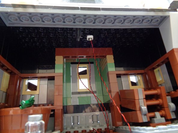
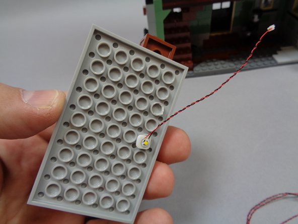
As shown in the first photo, attach the green light to the center of the attic ceiling.
-
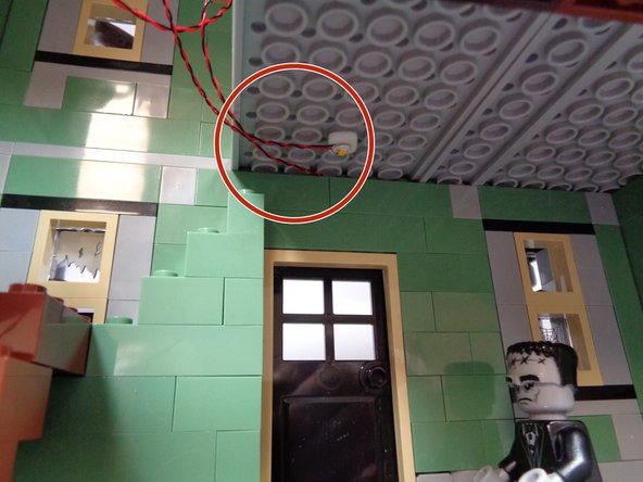
As shown in the second photo, pass the green light wire down through the hole in the attic floor, making sure to pass the wire BEHIND the horizontal floor support as shown by the red circle.
-
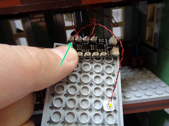
As shown by the green arrow in the third photo, connect the green attic light to plug #7 on the BRANCH09X adapter board.
-
-
-
Take the small "Warm White LEDs Bag" out of Bag 2. Inside will be four warm white Pico LED lights with three different wire lengths: one 3" (7.6cm) wire, two 6" (15.2cm) wires, and one 12" (30.4cm) wire. See the second photo for a comparison of wire lengths.
-
As shown in the third photo, attach a sticky square to the back of the warm white Pico LED light with the 3" (7.6cm) wire.
-
-
-
As shown in the first photo, mount the warm white Pico LED light to the underside of the attic floor section you removed earlier. Make sure to attach the light in the center, to one side as shown.
-
The second photo shows how the light should look from the side.
-
As shown by the green arrow in the third photo, connect the warm white Pico LED light wire to plug #6 on the BRANCH09X adapter board.
-
-
-
As shown in the first photo, attach a small sticky square to the back of the green Pico LED light with 3" (7.6cm) wire from the bag of green LEDs.
-
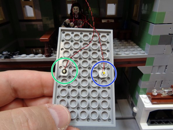
As shown in the second photo, mount the green Pico LED light on the opposite side of the attic floor from the warm white light.
-
The green circle in the second photo shows where the green light should be mounted, and the blue circle shows where the warm white light should be mounted.
-
As shown by the green arrow in the third photo, connect the green Pico LED light wire to plug #5 on the BRANCH09X adapter board.
-
-
-
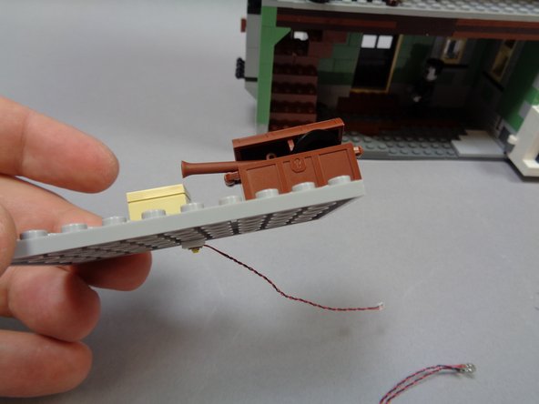
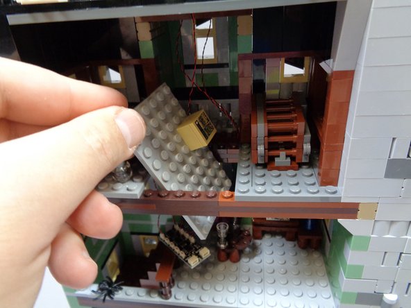
As shown in the first photo, remove the brown trunk from the attic floor.
-
As shown in the second photo, carefully pass the attic floor section up from the second floor, and rest it in the attic as shown in the third photo.
-
Do not fully re-attach the attic floor section yet.
-
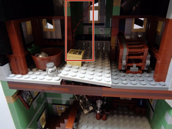
As shown by the red rectangle in the third photo, make sure all light wires pass to the left of the attic floor section. These will be the two wires from the rooftop ultraviolet lights and the one green light on the attic ceiling.
-
-
-
As shown in the first photo, remove the large center floor section from the second floor.
-
Take one of the warm white Pico LED lights with 6" (15.2cm) wire and attach a small sticky square to the back as shown in the second photo.
-
As shown in the third photo, attach the warm white light to the underside of the floor as shown, in the center and toward the front as shown.
-
-
-
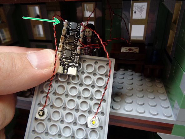
Take the small "Yellow LEDs Bag" out of Bag 2, and attach a small sticky square to the back of one of the yellow Pico LED lights as shown in the second photo.
-
As shown in the third photo, use a brick separator to make a space above the front doorway to pass the yellow LED light wire.
-
This can be a difficult process, as the bricks are attached firmly and it may be hard to pry with enough force to separate them. This is a good reason to keep your LEGO® building instructions close by, in case you need to re-build a section of your Haunted House.
-
-
-
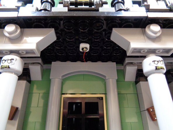
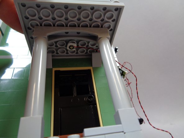
As shown by the red circle in the first photo, feed the wire from the yellow Pico LED light through the gap above the front door so the wire passes inside the house.
-
As shown in the second photo, mount the yellow Pico LED light on the porch ceiling in front of the front doorway.
-
Carefully press down on your Haunted House to re-attach the bricks you separated earlier. Make sure the wire from the front porch light passes between, not on top of, any studs.
-
As shown by the blue circle in the third photo, the wire from the front porch light should pass into the inside of the house.
-
-
-
As shown by the green arrow in the photo for this step. connect the yellow front porch light to plug #3 on the BRANCH09X adapter board.
-
DO NOT connect the light to Plug #4-- leave that plug open for now.
-
-
-
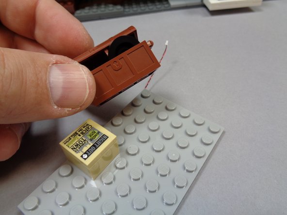
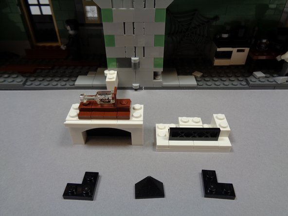
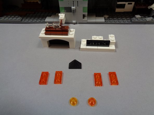
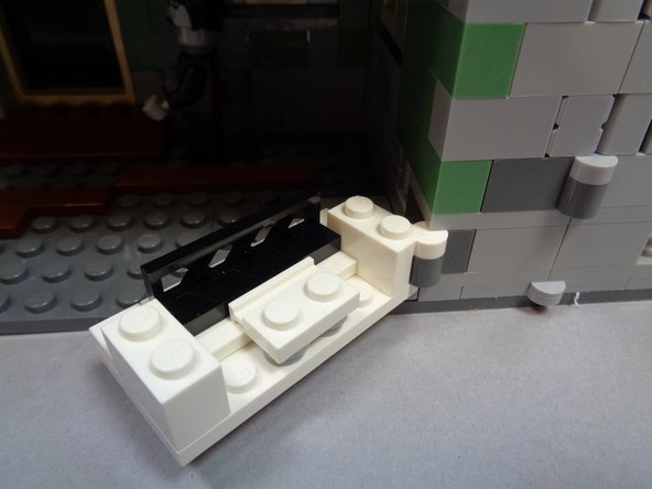
As shown in the first photo, separate the fireplace from its hinge and remove the three black pieces as shown.
-
As shown in the second photo, you will no longer need the two black "L" shaped plates.
-
Remove the transparent orange parts from Bag 2. You will use these to re-construct the fireplace with lights inside.
-
-
-
Take the small "Orange LEDs Bag" out of Bag 2, and remove the two lights with 18" (45.7cm) wires. These will be the lights with the longest wires in the bag of orange lights.
-
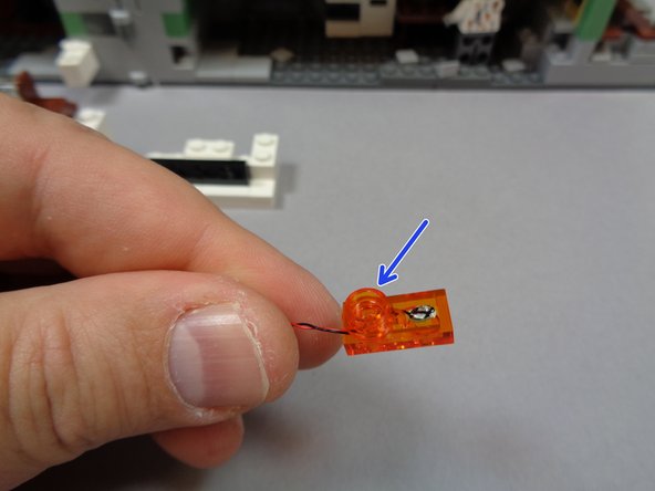
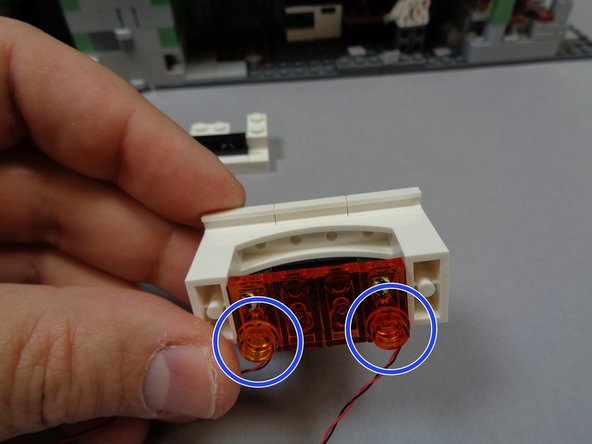
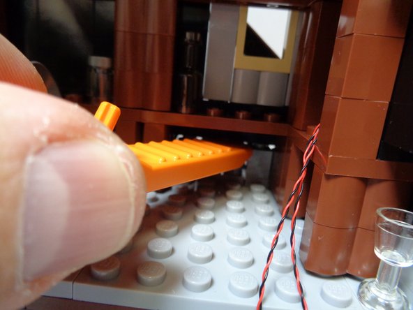
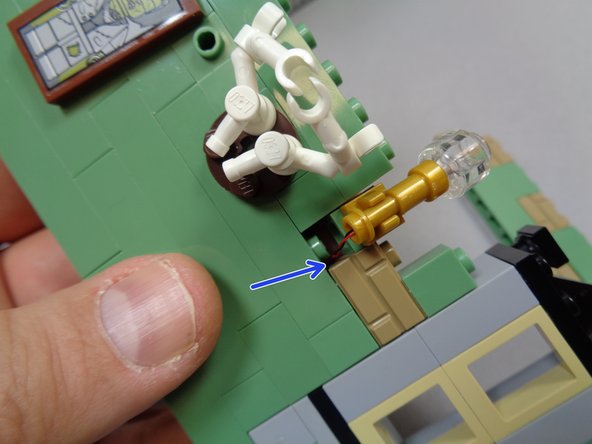
As shown in the second photo, place one of the orange Pico LED lights under the front stud of one of the two transparent orange 1x2 LEGO® plates included in Bag 2.
-
Make sure the light faces upward toward the top of the plate, and that the light wire passes toward the back of the plate as shown in the second photo.
-
As shown by the blue arrow in the third photo, use one of the transparent round 1x1 LEGO® plates from Bag 2 to hold the orange Pico LED light wire as it passes out the back of the 1x2 plate.
-
-
-
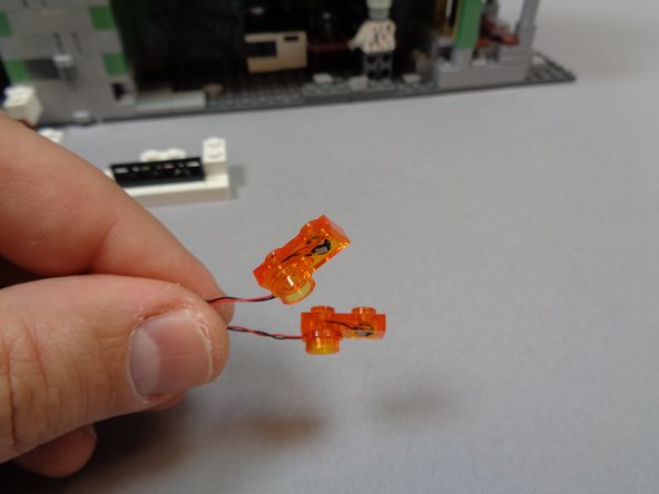
Repeat this process for the other orange Pico LED light with 18" (45.7cm) wire as shown in the first photo.
-
As shown in the second photo, attach the 1x2 transparent orange LEGO® plates with the orange lights to the bottom of the fireplace on either side.
-
As shown by the two blue circles in the second photo, make sure the round plates are at the back side of the fireplace.
-
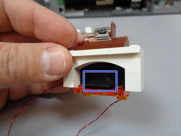
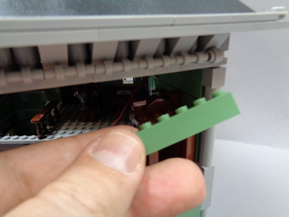
Attach the other two transparent orange 1x2 LEGO® plates and re-attach the black half-slope as shown by the blue rectangle in the third photo.
-
-
-
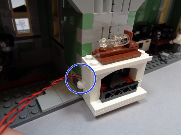
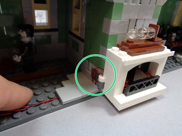
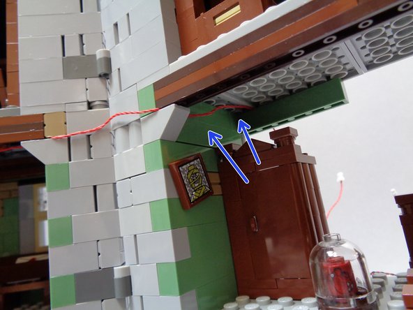
As shown in the photos for this step, re-assemble the fireplace and re-attach it to the wall-mounted hinge beginning with the bottom of the fireplace.
-
As shown by the red circle in the second photo and the blue circle in the third photo, make sure the two light wires pass between the fireplace and the wall ABOVE the hinge.
-
-
-
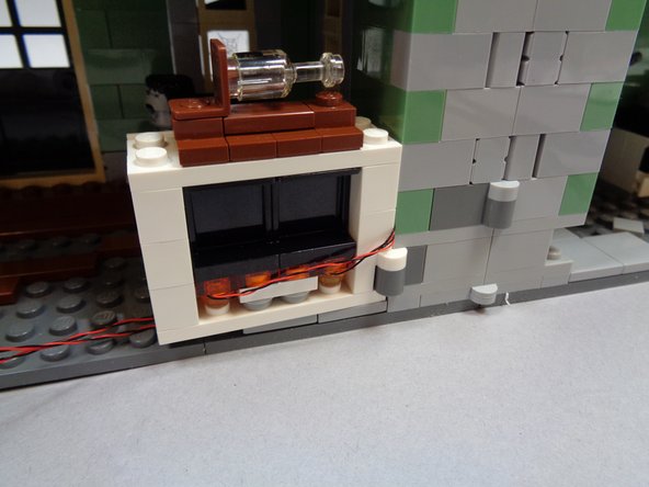
As shown in the first photo, remove the two large 2x2 LEGO® tiles behind the fireplace.
-
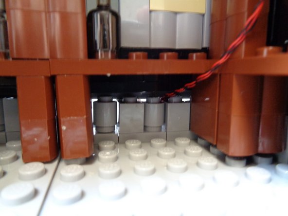
As shown in the second photo, pass the two light wires between the studs on the floor.
-
Make sure the wires pass between the studs, not on top of them. Wires passing on top of studs can become damaged.
-
As shown in the third photo, re-attach the two 2x2 LEGO® tiles you removed earlier.
-
As shown by the green circle in the third photo, make sure there is a little extra "slack" in the wire to allow the fireplace to move back and forth on the hinge without pulling the wires.
-
-
-
Move the fireplace back and forth to make sure it can still move with the lights mounted inside.
-
As shown in the photo, the fireplace should be able to rotate all the way inside the house and all the way back to the inside of the chimney when the house is open.
-
If the fireplace does not fully rotate or if wires get pulled, remove the two 2x2 LEGO® tiles from the floor and re-position the two light wires so there is more slack to allow the fireplace to move freely.
-
-
-
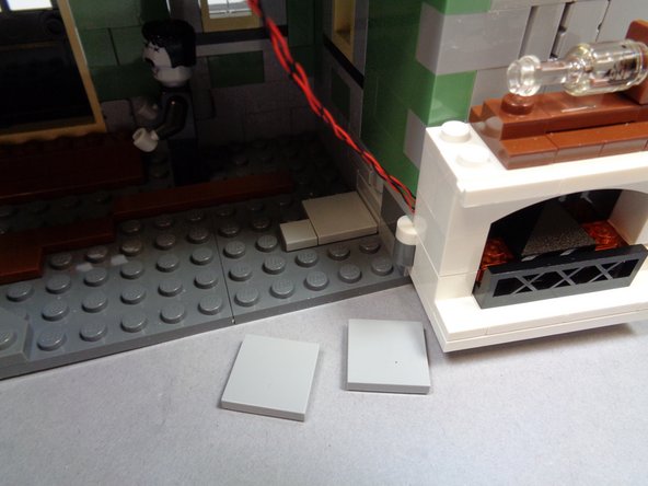
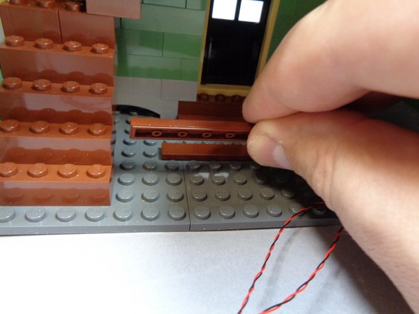
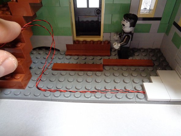
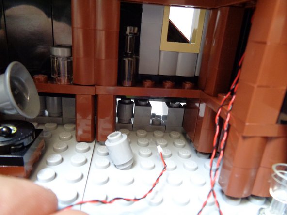
As shown in the first and second photos, remove the dark bluish gray plate and brown tile from the floor.
-
As shown in the third photo, run the two fireplace light wires along the floor and back toward the staircase.
-
Make sure all wires pass BETWEEN studs, not on top of them.
-
-
-
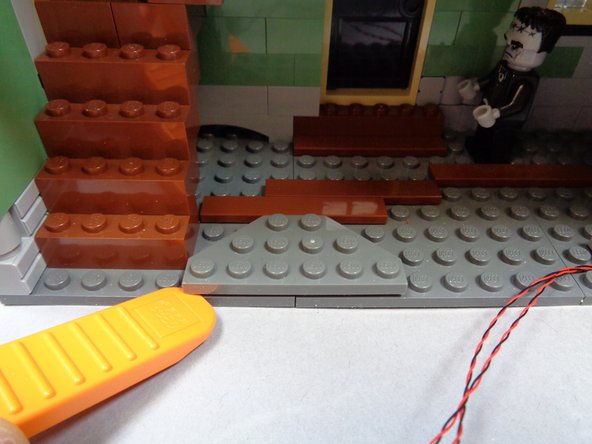
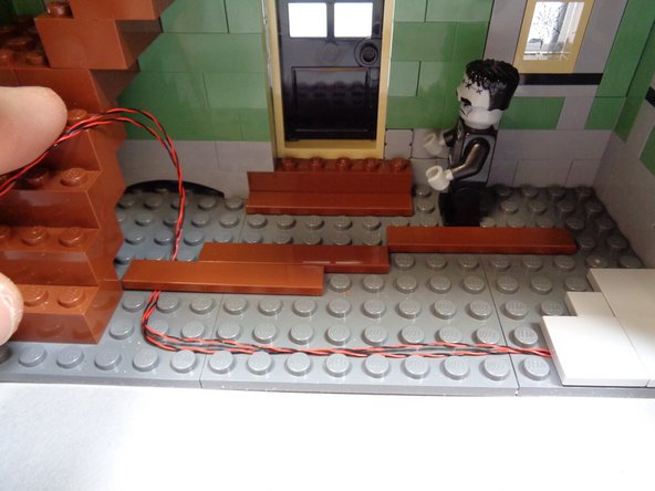
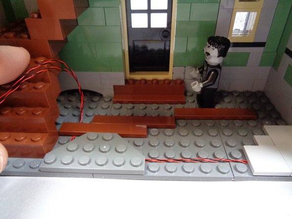
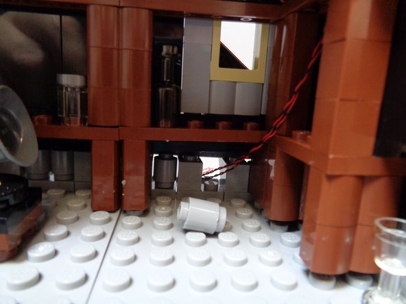
As shown in the first and second photos, replace the dark bluish gray plate and brown tiles you removed earlier. These should now be holding the two fireplace light wires in place.
-
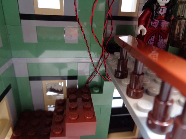
As shown in the third photo, remove the top four brown 2x4 bricks that make up the staircase.
-
-
-
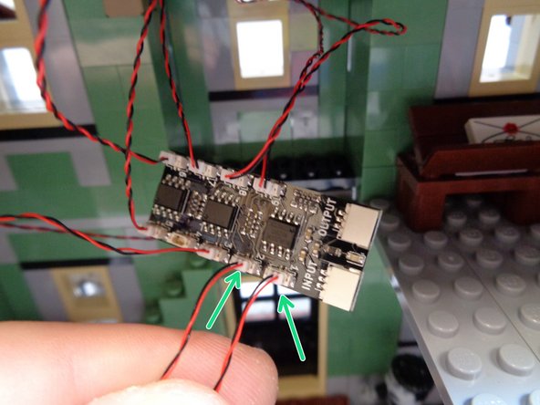
As shown by the two green arrows in the first photo, connect the two fireplace light wires to plugs #1 and #2 on the BRANCH09X adapter board.
-
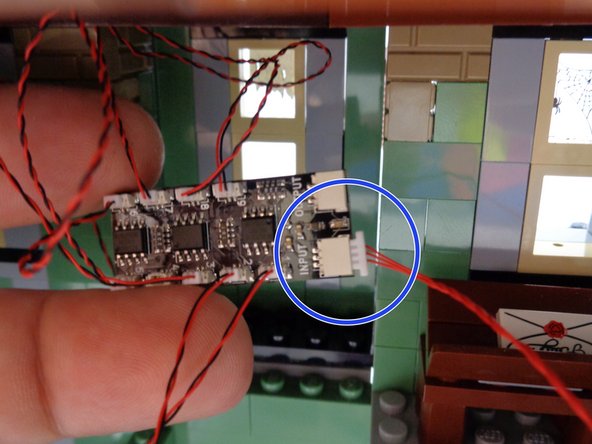
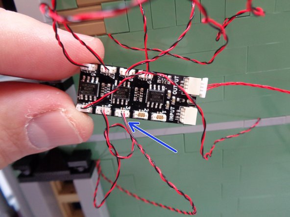
Take one of the red 12" (30.4cm) 3-wire cables from Bag 1 and connect one end to the large plug on the BRANCH09X adapter board labeled INPUT as shown by the blue circle in the second photo.
-
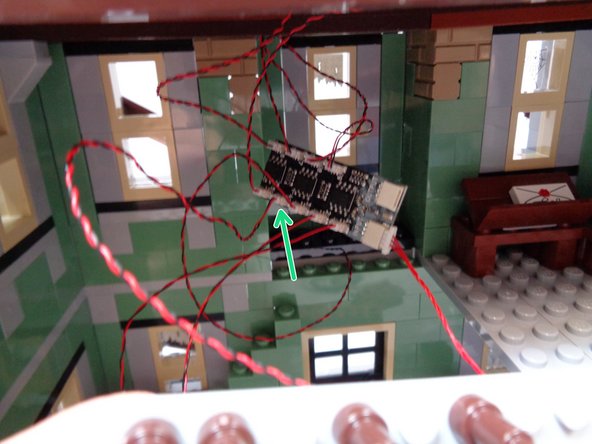
As shown by the green arrow in the third photo, connect the wire from the entryway warm white Pico LED light you mounted in Step 14 to the last open plug (#4) on the BRANCH09X adapter board.
-
-
-
As shown in the first photo, place two large sticky squares from Bag 1 on the back of the BRANCH09X adapter board.
-
As shown by the red circle in the second photo, make sure the light wires in the attic pass to the left of the floor section.
-
As shown by the blue arrow in the second photo, make sure the light wires pass around, not in front of, the center window.
-
Carefully press down on the attic floor plate to re-attach it to the frame of the house.
-
As shown in the third photo, attach the BRANCH09X adapter board to the underside of the attic floor section you just re-attached, so the board is in the center between the two Pico LED lights and so the red cable passes toward the rear as shown.
-
-
-
Re-position the second floor center section you removed earlier. As shown in the first photo, make sure the front porch light and the first floor warm white Pico LED light wires pass toward the left and to the side of the floor section as shown by the red circle.
-
As shown in the second photo, use your finger to move all light wires to the left side of the floor section.
-
As shown in the third photo, carefully press the center floor section back into place.
-
-
-
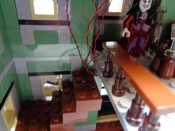
As shown by the orange circle in the first photo, take the two fireplace light wires and hold them along the wall where the staircase turns the corner.
-
leave just enough wire to reach the BRANCH09X adapter board on the ceiling. There will be a lot of extra wire coming from the fireplace-- you will hide that under the stairs later in this step.
-
As shown in the second photo, re-attach the lowest 2x4 LEGO® brick on the staircase. The brick should hold the two fireplace light wires in place along the front wall as shown by the orange arrow.
-
As shown by the blue arrows in the third photo, coil up any excess fireplace light wires under the staircase.
-
-
-
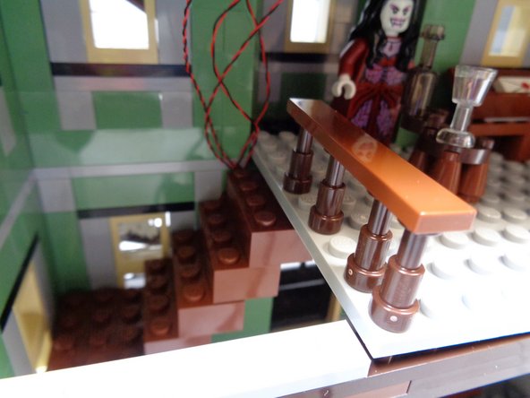
As shown by the photos in this step, re-attach the remaining three brown 2x4 LEGO® bricks to complete the staircase.
-
Each brick you re-attach should continue holding the fireplace light wires along the front wall.
-
You will need to lift the center floor section a little bit to place the last 2x4 staircase brick. Lift the floor section, replace the brick, and press the floor section back into place.
-
-
-
As shown in the photo, you should now have all sections of the stairs re-attached and all excess wires should be coiled up near the BRANCH09X adapter board.
-
-
-
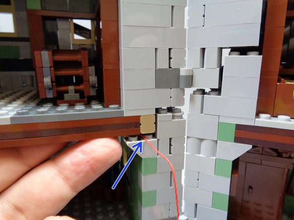
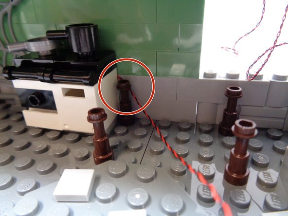
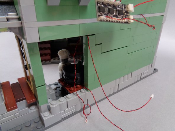
As shown in the first photo, use a brick separator to raise the second floor so you can run the red control wire connected to the BRANCH09X adapter on top of the light bluish gray floor support.
-
It may be difficult to separate the bricks enough to run the red wire. Move slowly and keep separating until there is enough room to pass the red wire BETWEEN the studs on top of the floor support. as shown by the blue arrow in the first photo.
-
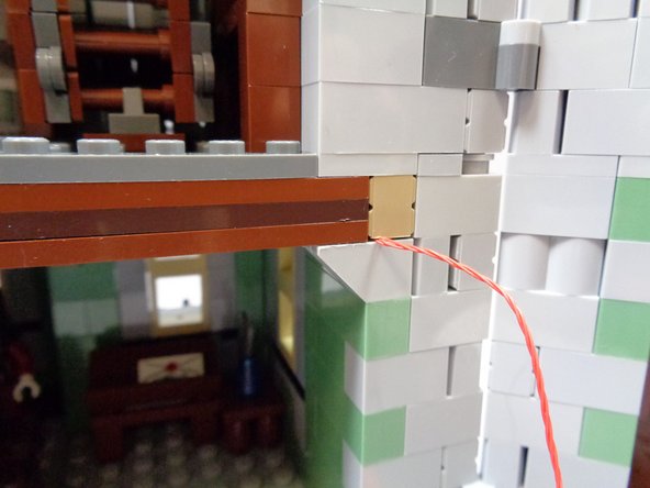
As shown in the second photo, make sure the red wire passes along the side of the drop-down attic stairs, so the stairs can still be lowered without hitting the red wire.
-
Carefully press down on your Haunted House to move the bricks back together.
-
-
-
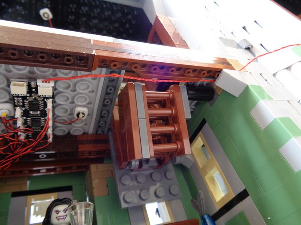
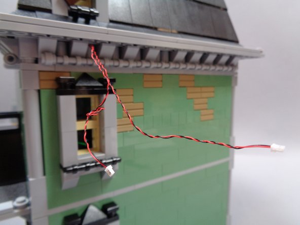
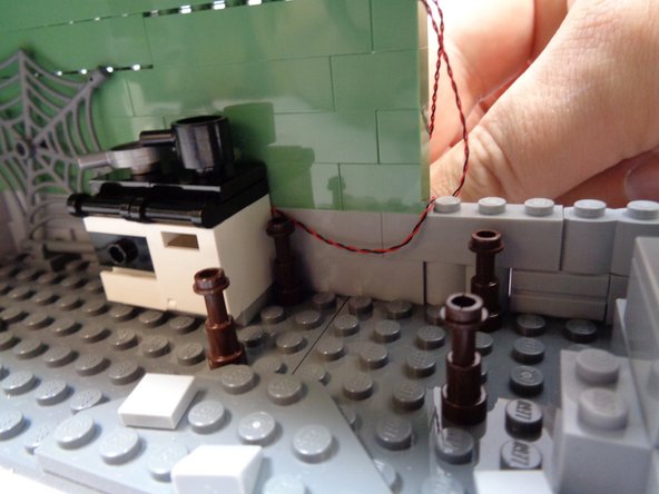
As shown in the first photo, now you will run the red wire to the other side of the house. Use a brick separator to create a space above the floor support on the back half of the house so you can pass the red wire between the studs on top of the floor support.
-
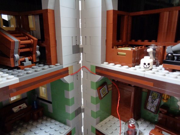
As shown by the blue line in the second photo, leave enough red wire between the two halves of the house that the house sections can be opened all the way.
-
As shown in the third photo, the red wire should bend up or down when you close the house.
-
-
-
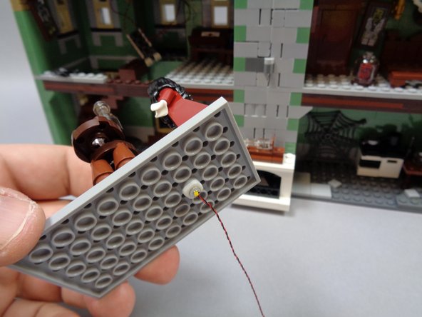
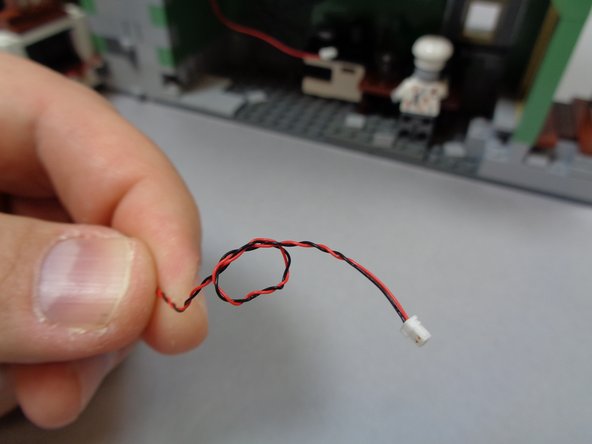
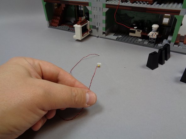
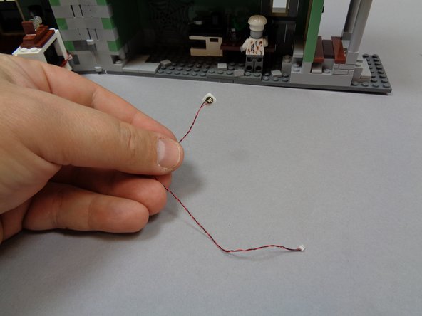
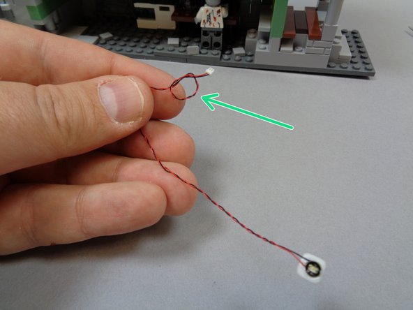
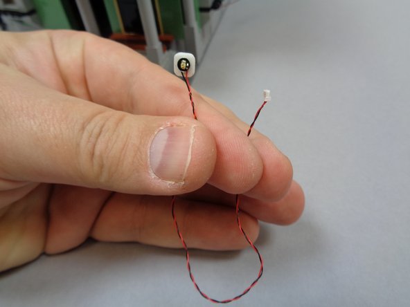
As shown in the first photo, take one of the orange Pico LED lights with a 12" (30.4cm) wire and attach a small sticky square to the back.
-
As shown in the second photo, tie a small knot in the wire by the plug. This will help you identify the light later.
-
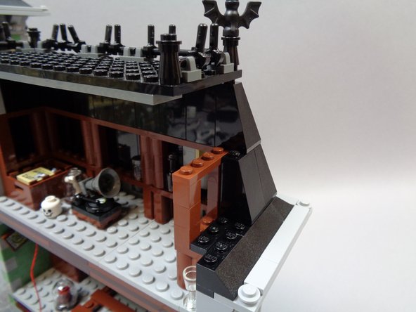
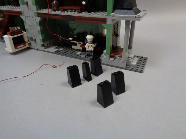
As shown in the third photo, begin removing black roof slope pieces from the rear attic roof to make room for running wires.
-
-
-
The first photo shows the roof pieces you should remove.
-
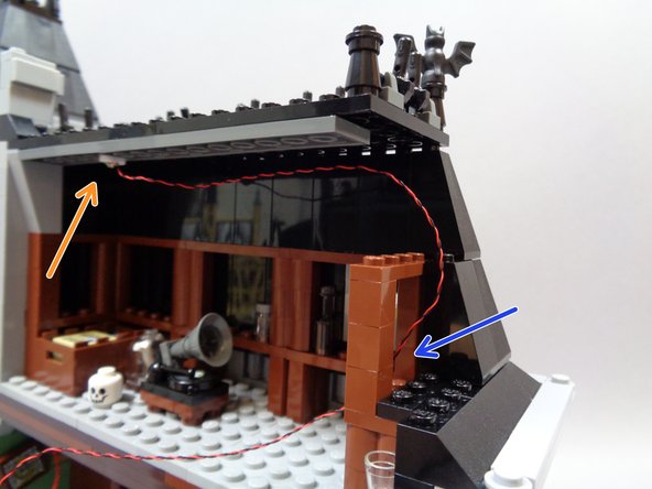
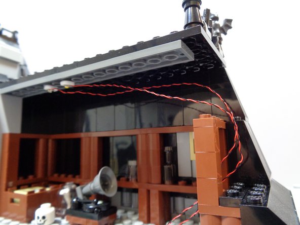
As shown by the orange arrow in the second photo, mount the orange Pico LED light on the attic ceiling and route the wire around and through the gap in the brown parts as shown by the blue arrow.
-
As shown in the third photo, take one of the warm white Pico LED lights with 12" (30.4cm) wire and attach a small sticky square to the back.
-
-
-
As shown in the first photo, mount the warm white Pico LED light on the attic ceiling next to the orange light you mounted earlier. Run the wires for the warm white light along the same path as the orange light wires.
-
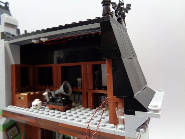
As shown in the second and third photos, re-attach the roof slope pieces you removed earlier.
-
When re-attaching the roof slopes, make sure all light wires run BETWEEN studs, not on top of them.
-
The light wires should run along the attic ceiling, down the side, and back through the brown frame parts as shown by the blue arrows in the third photo.
-
-
-
As shown in the first photo, use a brick separator to pry up the roof section and remove one of the round 1x1 LEGO® bricks as shown in the second photo.
-
As shown in the second and third photo, route the two attic light wires through the gap and out the back of the roof.
-
-
-
As shown in the first photo, re-attach the 1x1 round LEGO® brick you removed to make room for the attic light wires.
-
make sure the wires run BETWEEN studs, not on top of them.
-
As shown in the second photo, you should now have two wires extending out the back of the roof.
-
Remove the second BRANCH09X adapter board from Bag 1.
-
As shown by the blue arrows in the third photo, connect the light wire with the knot in it (the orange light) to plug #9 on the BRANCH09X adapter board.
-
As shown by the green arrow in the third photo, connect the other attic light wire to plug #8 on the BRANCH09X adapter board.
-
-
-
This is the most difficult section of the installation. Take your time, and make sure to have your LEGO® instruction manual handy in case you need help re-assembling any parts.
-
To make installation of the lights in the bedroom as easy as possible, you should remove the entire rear wall in the bedroom. The way the Haunted House is constructed, the wall itself is a single section that can be removed in one piece.
-
To begin, remove the rear second floor corner pillar as shown in the first photo.
-
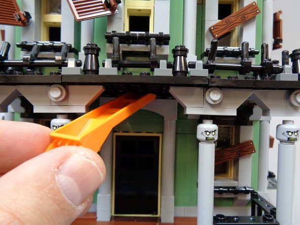
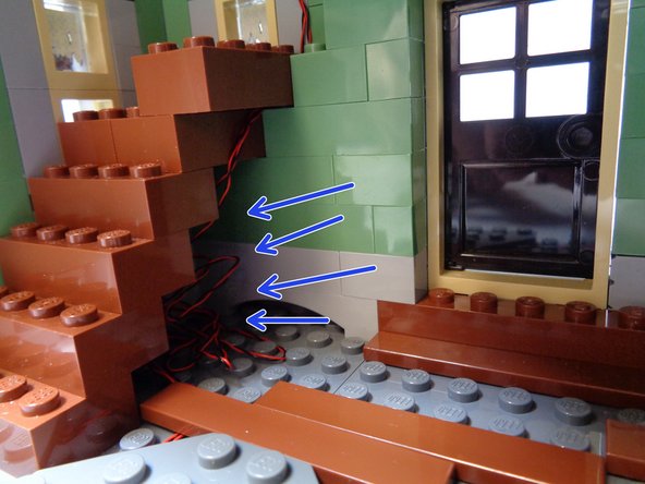
Using a brick separator, pry up the bricks just under the roof as shown in the second photo.
-
As shown by the blue arrows in the third photo, the goal is to loosen all bricks at the top of the bedroom wall, which will allow the wall to lift out.
-
-
-
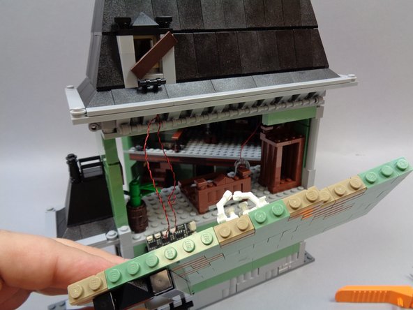
Once you have loosened the bricks along the top of the bedroom wall, you should be able to tilt the wall out and remove it in a single piece as shown in the first photo.
-
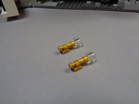
As shown in the second photo, remove the two gold wall sconces from the bedroom wall.
-
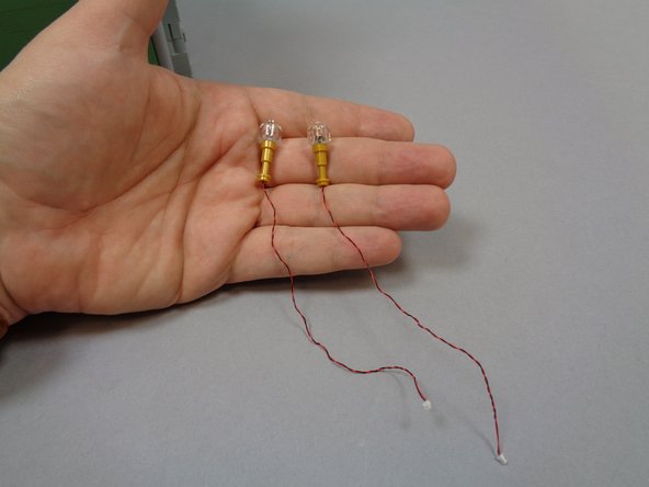
Inside the small bag of orange LED lights, there should be two replacement sconces with orange Pico LED lights pre-mounted as shown in the third photo.
-
-
-
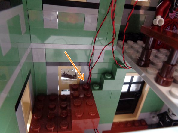
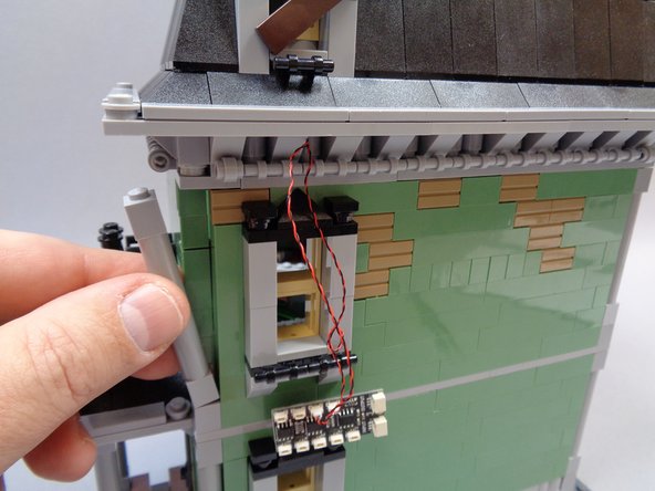
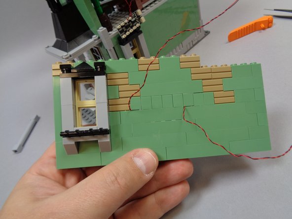
Remove bricks in the bedroom wall so you can access the bricks behind the sconces, then attach the Brickstuff sconces to the wall and run the light wires under the brick and to the side of the stud as shown by the blue arrow in the first photo.
-
Repeat for the second sconce, then re-assemble the bedroom wall as shown in the second photo.
-
As shown in the third photo, you should now have the two sconce light wires coming out the back of the bedroom wall.
-
-
-
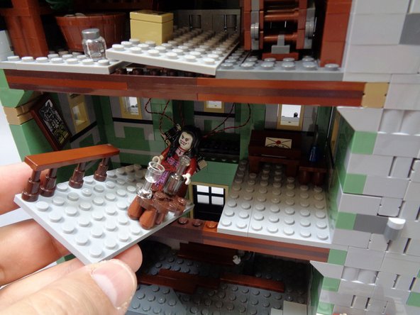
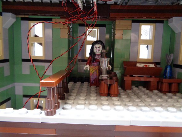
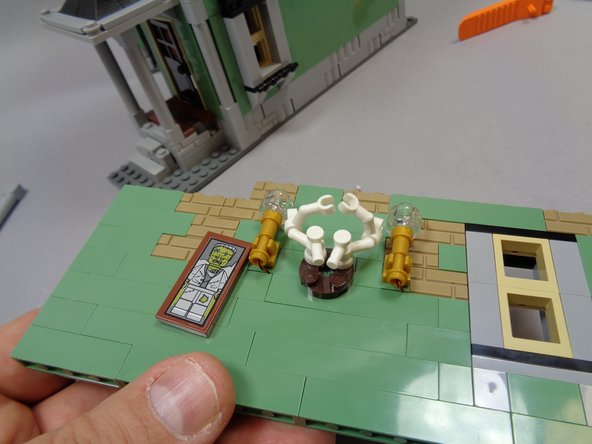
Now you will mount the red Pico LED light inside the heart inside the jar in the bedroom.
-
As shown in the first photo, remove the heart jar from the bedroom floor.
-
As shown in the second photo, take the small "Red LED Bag" out of Bag 2. Remove the single red Pico LED light from the bag.
-
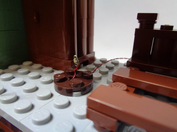
As shown in the third photo, mount the red Pico LED light so it sits upright and faces forward. Re-attach the round brown 2x2 LEGO® plate to hold the red light in place.
-
-
-
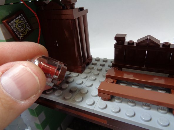
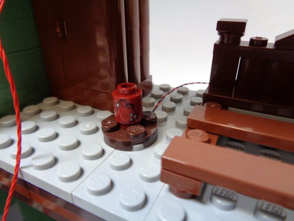
As shown in the first photo, re-attach the round red LEGO® brick with heart pattern so it covers the red Pico LED light. Make sure the heart pattern faces forward as shown in the photo.
-
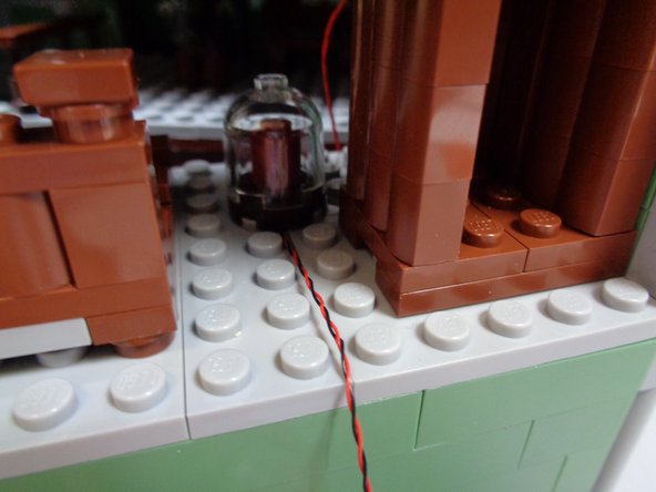
As shown in the second photo, re-attach the clear dome on top of the jar.
-
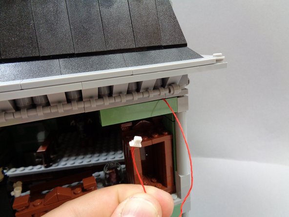
As shown in the third photo, you should now have the wire for the red Pico LED light extending out the back of the bedroom with the wire passing BETWEEN, not on top of, studs.
-
-
-
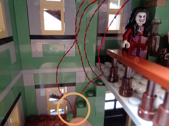
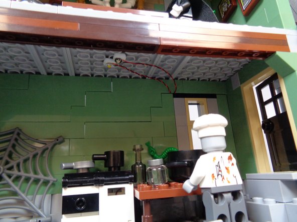
As shown in the photos for this step, you will now run the red control wire out the back of the bedroom wall.
-
it is important that the wire run along the bedroom ceiling as shown in the third photo.
-
Make sure the red wire passes between, not on top of, studs when running it out the back of the wall.
-
-
-
Carefully re-attach the rear bedroom wall, press down on the Haunted House frame to secure all bricks, and replace the light bluish gray pillar at the corner of the bedroom.
-
Take the two wall sconce light wires as shown in the second photo, and connect them to plugs #6 and #7 on the BRANCH09X adapter as shown by the green arrows in the third photo.
-
You can attach either sconce to either plug.
-
-
-
As shown in the first photo, you will now connect the red Pico LED light inside the heart jar.
-
As shown by the green arrow in the second photo, connect the heart jar light to plug #5 on the BRANCH09X adapter board.
-
Take the red control wire and connect it to the large OUTPUT plug on the BRANCH09X adapter board as shown in the third photo.
-
-
-
As shown in the first photo, you should now have plugs #5-9 on the BRANCH09X adapter board filled, and also the large OUTPUT connector.
-
As shown in the second photo, you can use the top of the second floor window frame to hold the attic wires in place.
-
-
-
As shown in the first photo, take the last green Pico LED light with 6" (15.2cm) wire and attach a small sticky square to the back.
-
As shown by the green arrow in the second photo, tie a small knot in the wire close to the connecting plug. This will help you connect the light later.
-
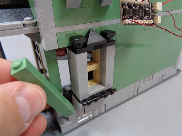
As shown in the third photo, use a brick separator to remove the corner pillar behind the kitchen.
-
-
-
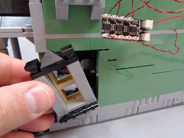
As shown in the first and second photos, remove the green wall section next to the kitchen window, then remove the window assembly itself.
-
As shown in the third photo, mount the green Pico LED light on the kitchen ceiling above the stove. The light wire should extend out the back of the kitchen wall.
-
-
-
As shown in the first photo, take the last warm white Pico LED light with 6" (15.2cm) wire and attach a small sticky square to the back.
-
As shown in the second photo, attach the warm white light to the kitchen ceiling next to the green light.
-
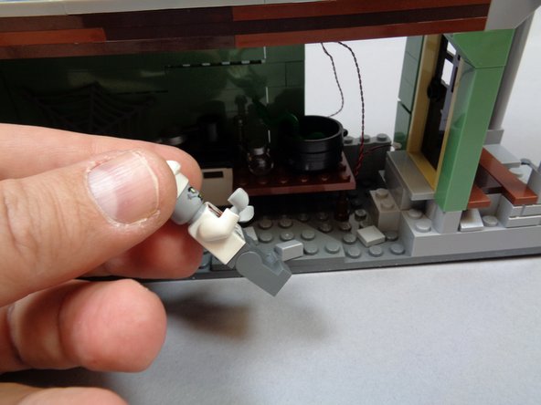
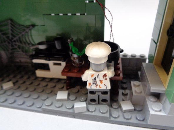
As shown in the third photo, remove the chef minifigure if you have it inside your kitchen.
-
-
-
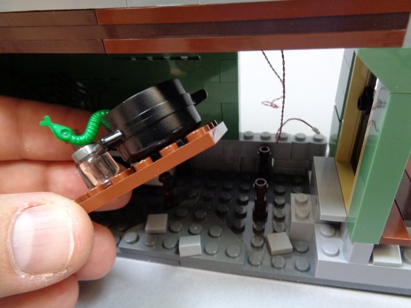
As shown in the photos for this step, remove the kitchen table and stove assembly. Open the oven-- this is where you will mount the last orange light in the next step.
-
-
-
Take the last orange Pico LED light with 12" (30.4cm) wire and attach a small sticky square to the back as shown in the first photo.
-
As shown in the second photo, feed the light through the back slot in the oven.
-
As shown in the third photo, mount the orange in the center of the oven facing upward.
-
-
-
Place the stove assembly back in place. As shown by the red circle in the first photo, make sure the oven light wire comes out the side of the oven.
-
As shown in the second photo, run the oven light wire along the kitchen wall and out the opening in the wall. The wire should run low enough along the wall that it will be hidden by the table.
-
Replace the table and chef as shown in the third photo.
-
-
-
As shown in the photos for this step, replace the kitchen window, wall pillar, and corner column.
-
Make sure all wires run between, not on top of, studs when replacing parts.
-
You should have three wires extending through the back of the kitchen wall:
-
Wire from the green kitchen light.
-
Wire from the warm white kitchen light.
-
Wire from the orange oven light.
-
The third photo shows how the two kitchen ceiling lights and their wires should look after re-attaching the window.
-
-
-
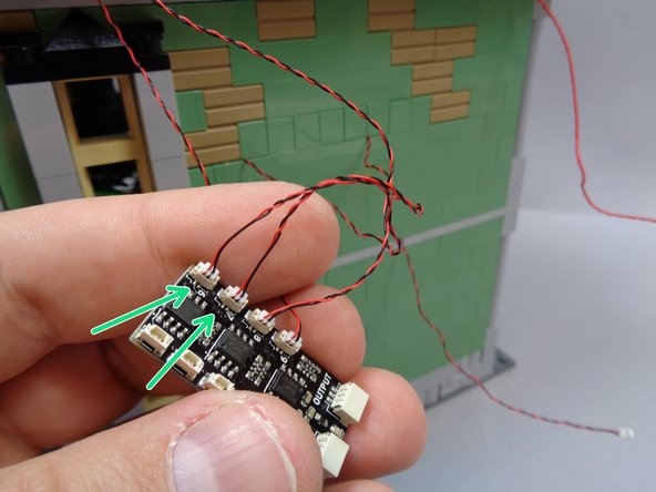
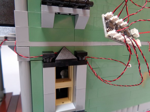
As shown by the orange arrow in the first photo, connect the green kitchen light wire-- the one with the knot you tied earlier-- to plug #4 on the BRANCH09X adapter board.
-
As shown by the blue arrow in the second photo, connect the warm white kitchen light wire to plug #3 on the BRANCH09X adapter board.
-
As shown by the yellow arrow in the third photo, connect the orange oven light to plug #2 on the BRANCH09X adapter board.
-
-
-
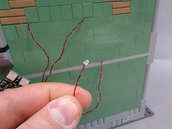
Take the last yellow Pico LED light with 6" (15.2cm) wire and attach a small sticky square to the back.
-
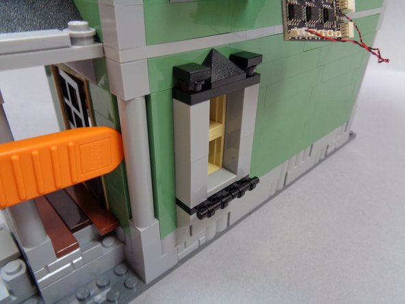
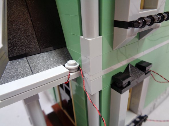
As shown in the second photo, mount the yellow light in the center of the side porch above the kitchen door.
-
As shown in the third photo, use the round 1x1 LEGO® plate on the side porch roof to hold the light wire in place.
-
-
-
As shown in the first and second photos, remove the black window top pieces form the kitchen window, and run the side porch light wire above the kitchen window.
-
Replace the black window top pieces to hold the side porch light wire in place.
-
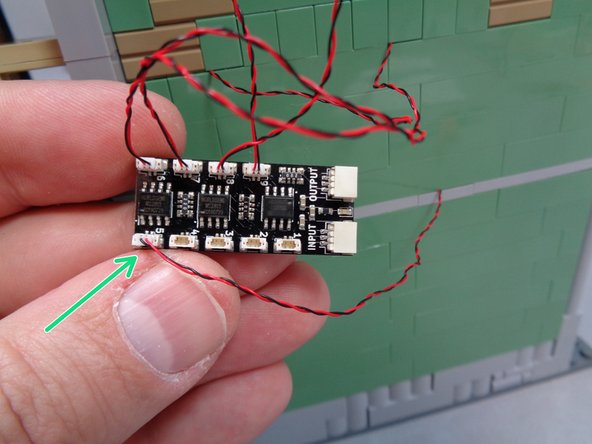
As shown by the blue arrow in the third photo, connect the side porch light to plug #1 on the BRANCH09X adapter board.
-
All nine small plugs on the BRANCH09X adapter board should now be connected.
-
-
-
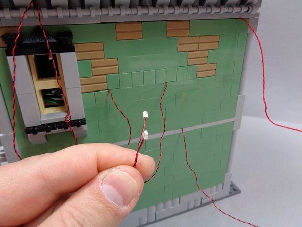
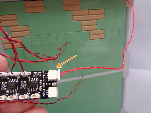
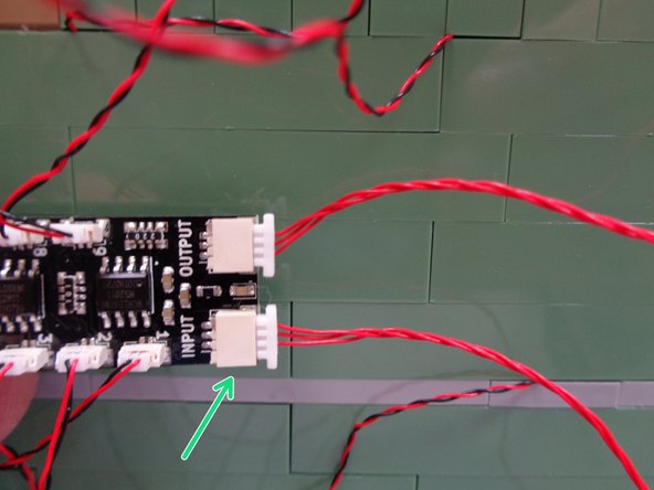
Take the second red 3-wire control wire from Bag 1 and connect one end to the large INPUT plug on the BRANCH09X adapter board as shown by the green arrow in the first photo.
-
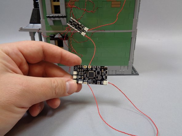
Remove the TRUNK08 master controller from Bag 1.
-
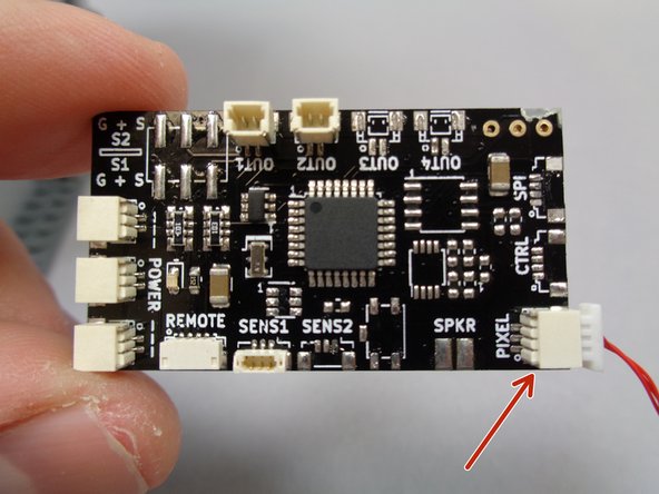
As shown by the red arrow in the second photo, connect the other end of the red control wire to the plug on the TRUNK08 master controller labeled "PIXEL".
-
The third photo shows how your setup should look.
-
-
-
Now you will connect the remote control receiver to the TRUNK08 master controller.
-
Remove the remote control receiver module from Bag 1. The first photo shows what the remote receiver module looks like.
-
As shown by the green arrow in the second photo, connect the small 4-wire plug from the remote receiver to the plug on the TRUNK08 master controller labeled "REMOTE".
-
As shown by the blue arrow in the third photo, connect the large power plug from the remote receiver to one of the "POWER" plugs on the TRUNK08 master controller.
-
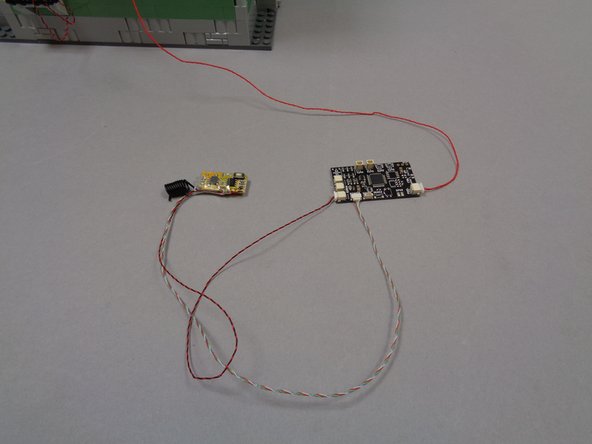
The third photo shows what your setup should look like with the remote receiver connected to the TRUNK08 master controller.
-
-
-
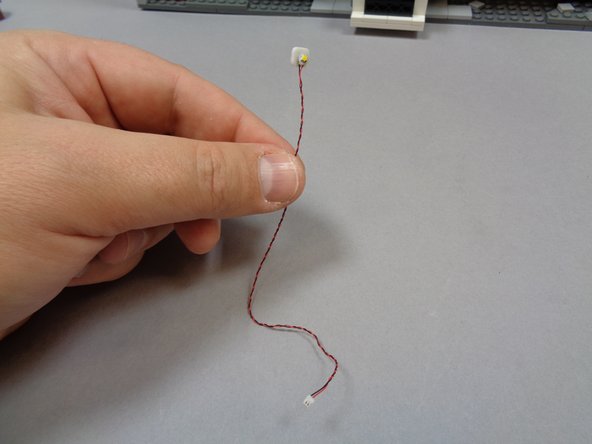
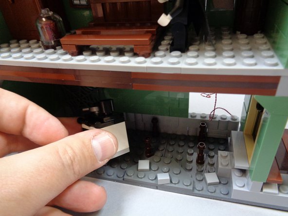
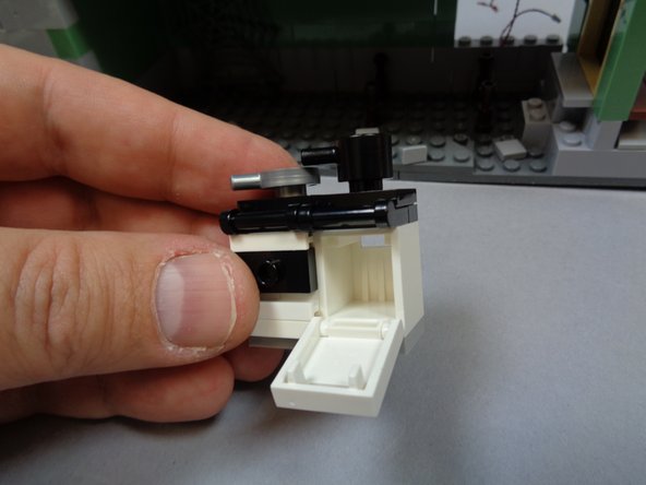
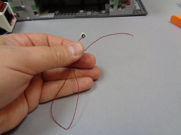
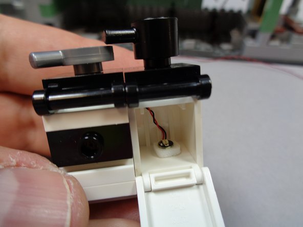
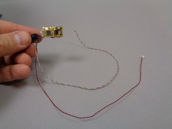
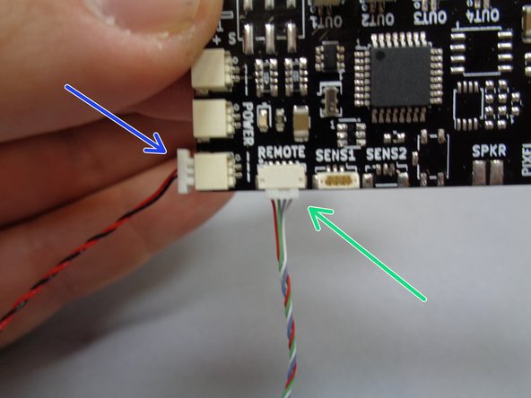
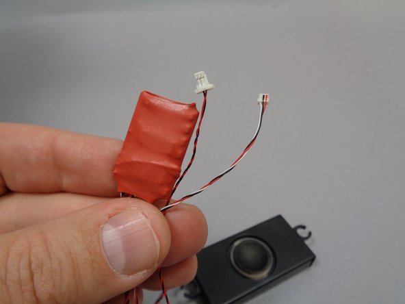
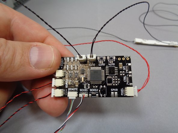
Remove the sound module from Bag 3. As shown in the first photo, the sound module has two wires: one red/black power wire with a large plug and one red/white/black cable control wire with a small connector.
-
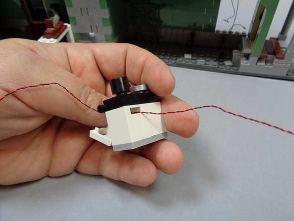
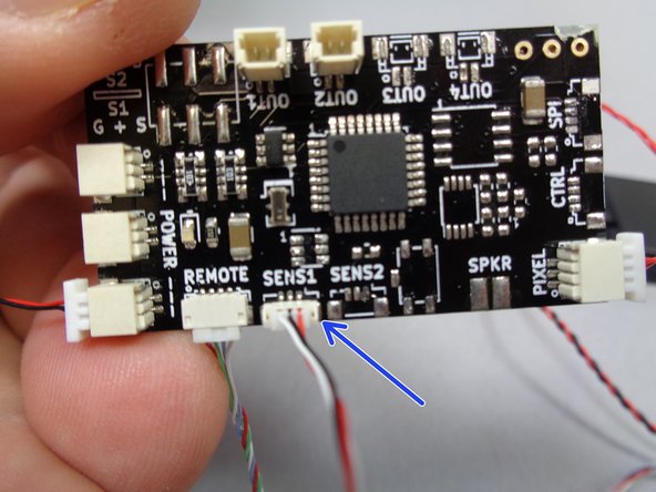
As shown by the blue arrow in the second photo, connect the red/white/black control wire with the small connector to the plug on the TRUNK08 master controller labeled "SENS1".
-
As shown by the orange arrow in the third photo, connect the red/black power wire from the sound module to one of the "POWER" plugs on the TRUNK08 master controller.
-
-
-
You will now connect the cool white and warm white light strips that simulate lightning.
-
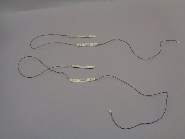
Take the four light strips from Bag 2 and the four 12" (30.4cm) black connecting cables from Bag 1 and make two strings of lights by connecting two light strips end-to-end as shown in the first photo.
-
To get the best lightning effect, we recommend using one warm white light strip and one cool white light strip in each "string" of lights. You can tell the cool white strips from the warm white because the cool white strips do not have a clear coating.
-
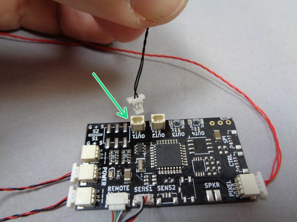
As shown by the green arrow in the second photo, connect one of the light strings to the large plug on the TRUNK08 master controller labeled "OUT1".
-
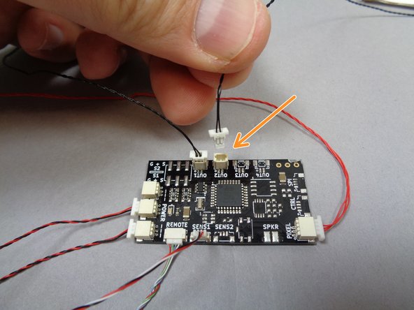
As shown by the orange arrow in the third photo, connect the other light string to the large plug on the TRUNK08 master controller labeled "OUT2".
-
It does not matter which string you connect to which plug.
-
To enhance the lightning effect, you can add additional light strips by purchasing strips and connecting wires from our website. You can connect up to 25 strips to each output on the TRUNK08 master controller.
-
To get even brighter lighting, you can use our high-power warm white LED lights. One high-power light can be connected to each output.
-
-
-
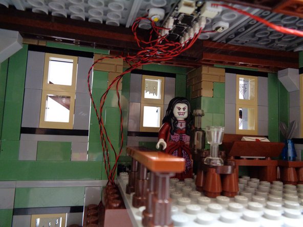
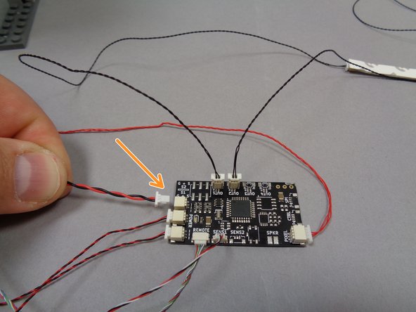
The first photo shows what your TRUNK08 master controller should look like after connecting all lights, the remote receiver wires, and the sound module wires.
-
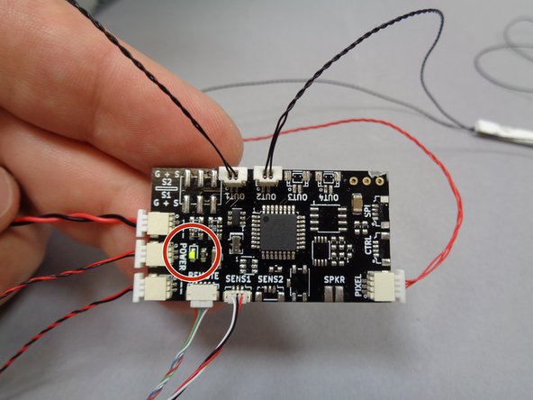
As shown by the orange arrow in the second photo, connect the plug from the USB power cable to the last open "POWER" connector on the TRUNK08 master controller.
-
Connect the USB cable to a power source. As shown by the red circle in the third photo, the green power light on the TRUNK08 master controller should turn on.
-
-
-
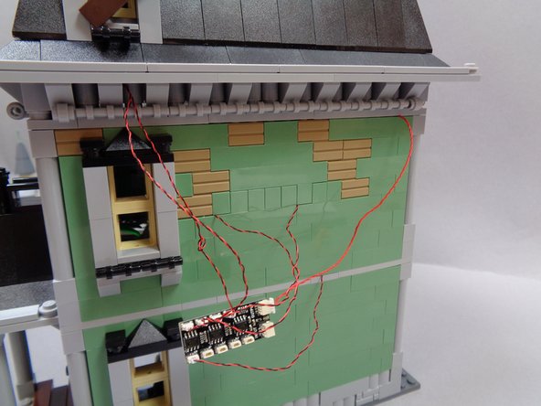
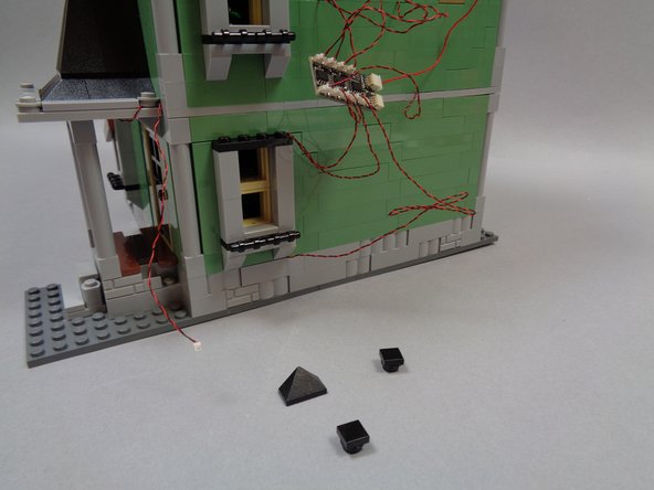
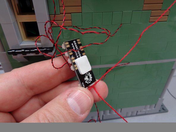
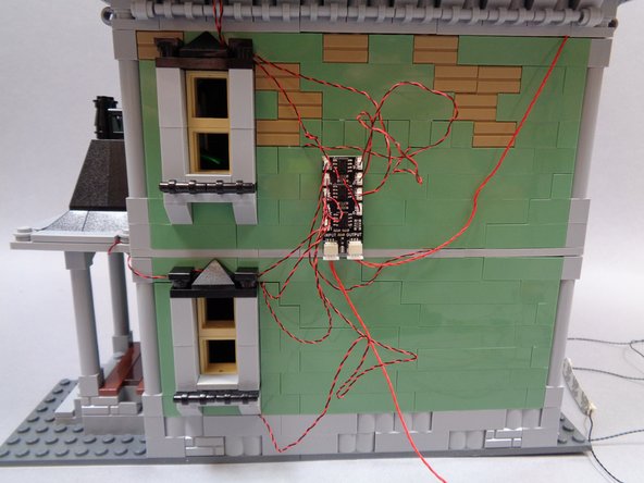
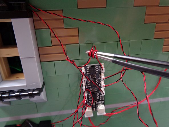
As shown in the first photo, use one of the large sticky squares from Bag 1 to attach the BRANCH09X adapter board to the back of the house.
-
You will have extra light wires in back of the house. You can use a tweezers or similar tool as shown in the third photo to coil up any excess light wires.
-
-
-
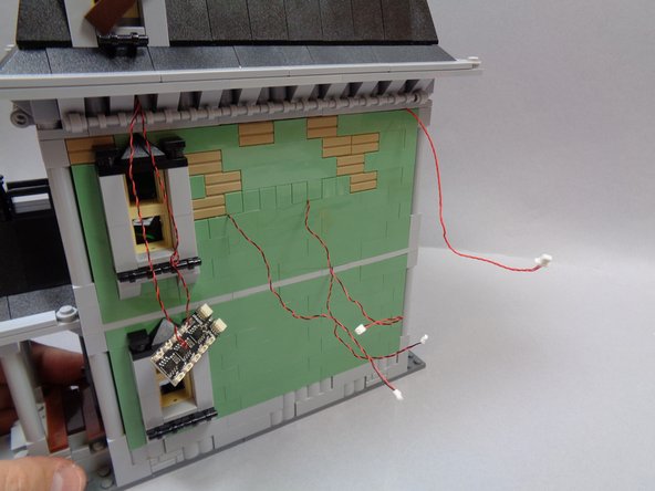
The first photo shows what your setup should look like after coiling up any excess light wire.
-
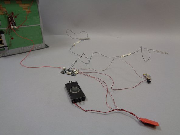
The second and third photos show the final setup after all wires have been connected.
-
Only the single red control wire connects to the house, leaving the TRUNK08 master controller, remote receiver module, and sound module able to be mounted inside another structure or hidden.
-
For best lightning results, position one light strip string to the left of the Haunted House and the other strip to the right of the house.
-
-
-
Click here to read about the functions and operation of the remote control.
-
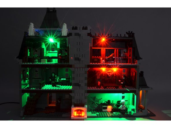
We hope you enjoy your Haunted House light + sound kit!
-
THANK YOU very much for your support of our products!
-