
Tools
No tools specified.
Parts
-
-
First, you will mount the blue lights along the edges and top of your Super Star Destroyer. The Brickstuff kit includes a total of 28 blue lights. You will use 24 lights in the setup-- 4 lights are extras in case you damage any during installation.
-
You will mount seven (7) blue lights on each side of the ship, for a total of 14 lights along the edges and 10 lights along the top center section.
-
The blue lights are supplied in pairs, with two lights connected to each main wire and connecting plug. So you will use seven pairs along the edges.
-
The illustration included with this step shows how the lights in this section are connected. You will use two BRANCH15 adapter boards, one BRANCH04 adapter board, and two 12" connecting cables to connect the blue lights.
-
Note that depending on when your kit was made, it may include 12" cables that have black wires or red and black wires, and the wires may be thicker than those shown in the photos here. That is ok.
-
The illustration is also included with the downloadable PDF featured at the beginning of this guide (download Version 1.7 or Version 1.9 depending on which version of the A10 adapter board was included with your kit). A printed copy of this document was also included with your kit.
-
Note that one pair of blue lights is located in the center front section of the ship.
-
See the next step for photos showing how to mount the lights.
-
-
-
The blue lights and connecting parts are contained in Bag 3 of your kit.
-
The blue lights are small enough to fit under a LEGO plate. Bag 3 includes 26 transparent round LEGO plates-- this is two more than you will need (the two extras are in case you lose some during installation).
-
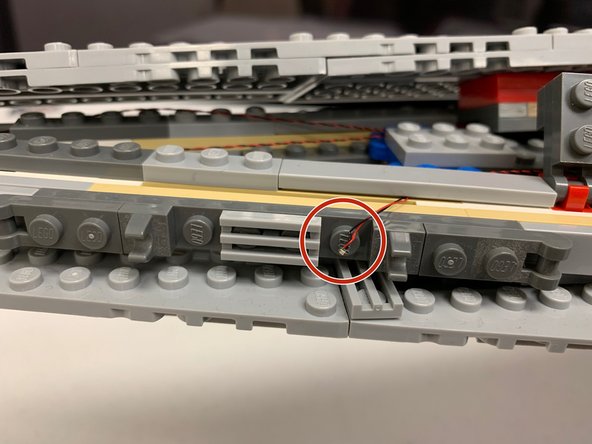
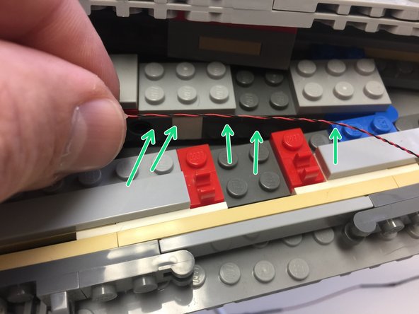
To mount each blue light, center the tiny LED part on top of a LEGO stud along the edge of the ship as shown by the red circle in the first photo.
-
Using your fingernail, gently bend the light wire along the edge of the stud. This will make it easier to snap the transparent plate on top.
-
Carefully snap the transparent plate on top of the blue LED, and press so the plate is firmly attached.
-
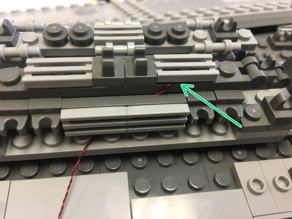
As shown in the second and third photos, you can secure the LED wires beneath the gray tiles that run along the edge of the ship. Just make sure to run all LED wires between, not on top of, any studs as shown by the green arrow in the second photo.
-
Repeat this process for all 14 lights along both sides of the ship.
-
-
-
The first photo in this step shows how to mount the two front blue lights.
-
As shown in the illustration in the first step, you also need to mount two blue lights in the front center section of the ship. The second photo in this step shows how to run the wires and attach the blue light under a grille tile piece (see green arrow).
-
At the end of this step, you should have a total of 16 blue lights mounted: 14 along the two edges of the ship and two in the front center section. You should have all lights connected to a plug on one of the two BRANCH15 adapter boards.
-
-
-
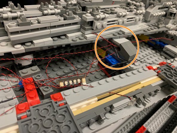
The photos in this step show how you can hide the light wires inside the open parts of the ship. The light wires have plugs that are small enough to fit through Technic brick holes (see the orange circle in the first photo), so you can use open holes to coil extra wire.
-
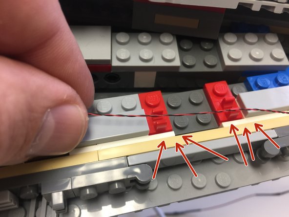
The second and third photos show a very important warning. Do not let any light wires run through the center of any hinge clips (see the red arrows in the second photo)-- this will cause damage when the hinge tops are re-attached.
-
Make sure all wires run behind, not on top of, hinge clips as shown by the green arrows in the second photo.
-
-
-
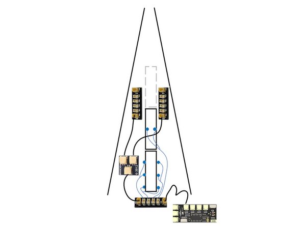
As shown in the illustration for this step, you will use the remaining parts in Bag 3 to mount the remaining eight blue lights. Six will be mounted in the rear center section and two will be mounted in the center top (removable) section.
-
The illustration is also included with the downloadable PDF featured at the beginning of this guide.
-
Connect the blue lights shown in the illustration to the four plugs on the BRANCH15 adapter board, then connect one of the large plugs on the BRANCH15 board to the BRANCH04 board you connected earlier. Connect the other large plug to the OUT1 connector on the TRUNK11 effect controller from Bag 1 as shown.
-
Connecting plugs are fragile. When inserting plugs, press straight down and do not pull to the side. Pulling a plug to the side can cause it to snap off the circuit board.
-
-
-
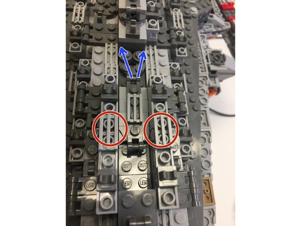
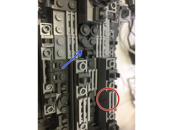
Mounting the blue center lights can be tricky, as the wires need to run under many parts in order to be hidden.
-
The photos in this step show how the lights should be mounted: lights should be mounted beneath grille tiles (red circles) and wires should run down the sides and between bricks toward the BRANCH15 adapter board (blue arrows).
-
Take your time with this step in order to get the best results. Mount lights carefully, and if you need to test any lights after mounting, you can connect one of the two power sources included with this kit to the BRANCH15 adapter board.
-
If you damage any lights during installation, two extra pairs are provided.
-
-
-
Carefully remove the rear center engine assembly. This is the section that has seven engines.
-
When mounting the orange lights contained in Bag 4, it is important to note the different ways the lights are mounted depending on the size of the engine.
-
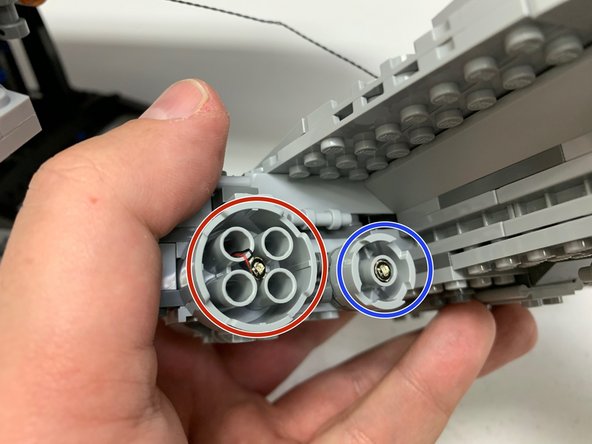
The red circle in the first photo shows how the lights are mounted inside large engine sections: the LED wire runs back from the front through one of the open holes.
-
The blue circle in the first photo shows how the lights are mounted inside the smaller engine sections. These are more difficult to mount, since the LED wire must pass through the center. This is also where the black Technic axle passes, so the LED wire will be pinched by the Technic axle and will fit very tightly.
-
Two extra orange lights are included in Bag 4 in case you damage any during installation.
-
-
-
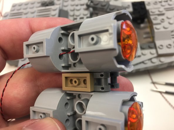
The photos in this step show how to mount the first seven engine lights-- these are the lights in the removable center engine section.
-
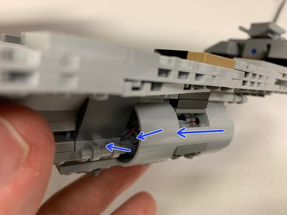
The blue arrows in the second photo show how the wires should run for the larger engines.
-
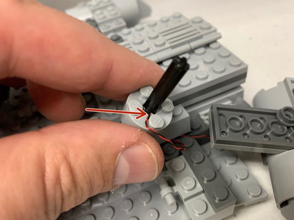
The red arrow in the third photo shows how the smaller engines will have the LED wire wedged next to the black Technic axle once mounted. These are the most likely to become damaged during installation, so re-insert the Technic axle carefully after mounting the LED.
-
-
-
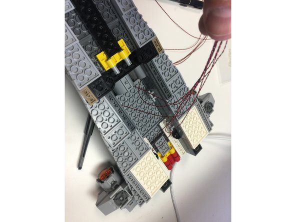
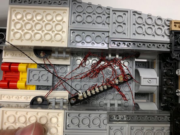
As shown by the photos in this step, coil up any excess wire coming from the seven center engines and connect all LED wires to the BRANCH10 adapter board from Bag 4. Connect one of the 12" connecting cables from Bag 4 to one of the large connectors on the BRANCH10 adapter board.
-
Depending on when your kit was manufactured, the BRANCH10 adapter supplied may have either side-facing or top-facing connectors. The LED lights will still connect the same way. Note that your kit may also have a BRANCH10 adapter with 12 small plugs.
-
The BRANCH10 adapter board shown in the second photo has top-facing connectors. Your BRANCH10 may look different.
-
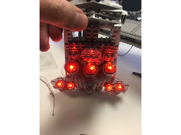
As shown in the third photo, temporarily connect a power source to the other large connector on the BRANCH10 adapter board and verify that all seven orange lights are working.
-
-
-
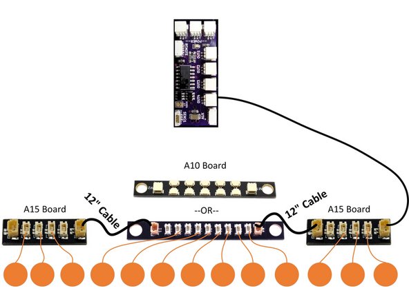
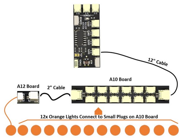
Depending on when your kit was manufactured, you will have one of three different designs of BRANCH10 adapter board: one with top-facing connectors (9 total small plugs), one with side-facing connectors and 10 total small plugs, or one with side-facing connectors and 12 total small plugs. The operation of all three designs of board is identical.
-
The illustration in the second photo shows the first two types of BRANCH10/A10 adapter boards: with 9 top-facing small plugs and with 10 side-facing small plugs. The illustration in the third photo shows the last type of BRANCH10 adapter board: with 12 side-facing small plugs.
-
If the parts in your kit include either of the first two types of BRANCH10/A10 adapter, follow the diagram in the second photo:
-
Carefully remove the two 3-engine assemblies from the underside of the ship, and mount the remaining six engine lights. Use the remaining two BRANCH15 adapter boards and the two remaining 12" connecting cables to connect all engines together.
-
If the parts in your kit include the third type of BRANCH10/A10 adapter, follow the diagram in the third photo:
-
Carefully remove the two 3-engine assemblies from the underside of the ship, and mount the remaining six engine lights. Connect one light to the BRANCH12 adapter board, and connect the other 12 lights to the plugs on the BRANCH10/A10 adapter board. Use the 2" connecting cable to connect the BRANCH12 and BRANCH10 adapter boards together.
-
Finally, connect the engines to the OUT4 plug on the TRUNK11 effect controller.
-
If any lights don't light, two spares are included with your kit. If you run out of spare lights, you can purchase additional orange lights in packs of 2 from our website (search for Orange Pico LEDs).
-
-
-
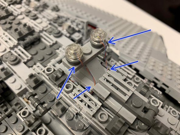
Bag 5 includes two pairs of cool white LEDs. You will use one of these pairs to mount as marker lights on top of the ship. Two transparent round 1x1 LEGO plates are also included in Bag 5.
-
The second pair of cool white LEDs is included as spare if needed.
-
As shown in the first photo, mount the two cool white lights on top of the ship and secure with the two transparent plates. Carefully run the LED wires down into the center of the ship as shown by the blue arrows.
-
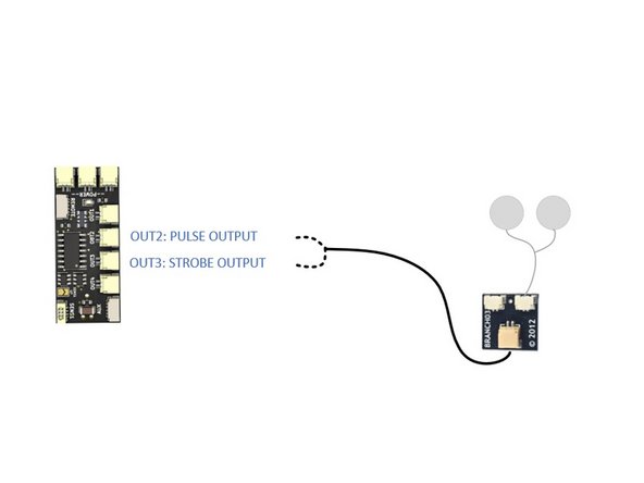
Connect the LED pair to one of the small connectors on the BRANCH03 adapter board included in Bag 5. Use the 6" connecting cable in Bag 5 to connect the BRANCH03 adapter board to the TRUNK11 effect controller.
-
You have two options for connecting the marker lights, as shown in the second photo/illustration.
-
Connecting the lights to the OUT2 connector on the TRUNK11 effect controller provides a pulsed lighting effect.
-
Connecting the lights to the OUT3 connector on the TRUNK11 effect controller provides a strobing effect.
-
-
-
You should now have all lights mounted and connected to the TRUNK11 effect controller.
-
Bag 2 contains the remote receiver and remote control unit.
-
As shown in the illustration, connect the 4-wire cable from the remote receiver (the cable with red, white, green, and blue wires) to the connector on the side of the TRUNK11 effect controller. This plug is labeled "REMOTE" on the circuit board.
-
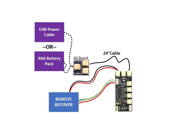
There are three main power connectors on the TRUNK11 effect controller. Connect the 2-wire cable from the remote receiver (the cable with red and black wires) to one of the power plugs as shown in the illustration (it doesn't matter which power plug you select).
-
Your kit includes two power sources: one AA battery pack and one USB cable. Inside bag 1 there should be one 24" power cable and one BRANCH04 adapter board. Connect these as shown in the illustration, then connect either the AA battery pack or USB cable to the BRANCH04 adapter to power your setup.
-
The 24" cable is included in case you want to use the USB cable and run the power outside the ship. You can use the 24" cable to run down the ship's stand, then connect to the USB cable.
-
You can use the AA battery pack to power the setup internally (no external wires).
-
-
-
Connect one of the two power sources to the TRUNK11 effect controller. You should see the green LED on the TRUNK11 controller turn on.
-
You can control all lights and effects using the remote control. Each of the four buttons has two functions: one function is activated by a "short press" on the button, and the other function is activated by a "long press" on the button.
-
BUTTON A: Short Press = turn the blue lights on and off. Long Press = adjust the brightness of the blue lights.
-
BUTTON B: Short Press = turn the pulse output on and off (if you have used this for the two marker lights). Long Press = adjust the speed of the pulse effect.
-
BUTTON C: Short Press = turn the strobe output on and off (if you have used this for the two marker lights). Long Press = adjust the speed of the strobe effect.
-
BUTTON D: Short Press = turn the engines on and off. Long Press = adjust the pulse speed of the engines.
-
The remote transmitter is locked to the receiver, so only the remote can control the receiver. Other remotes will not interfere with the signal.
-
You can mount the remote receiver inside the ship-- the remote does not need "line of sight" to operate. The remote should have at least a 50ft (15.2m) range.
-
-
-
All light settings (effects, brightness/speed, etc.) are saved when power is turned off.
-
You can use the extra lights provided with this kit in other areas of the ship. As long as there is an available small connecting plug on a BRANCH03, BRANCH10, or BRANCH15 adapter board, you can connect any light in this kit to it.
-
If you use the strobe effect for the two marker lights (OUT3 on the TRUNK11 effect controller), you can try connecting the blue lights to the pulsing output (OUT2 on the TRUNK11 effect controller) for a different setup.
-
You can purchase additional adapter boards and connecting cables from our website to split the blue lights between OUT1 and OUT2 on the TRUNK11 effect controller if, for example, you wanted to have some blue lights "always on" and have others pulse.
-
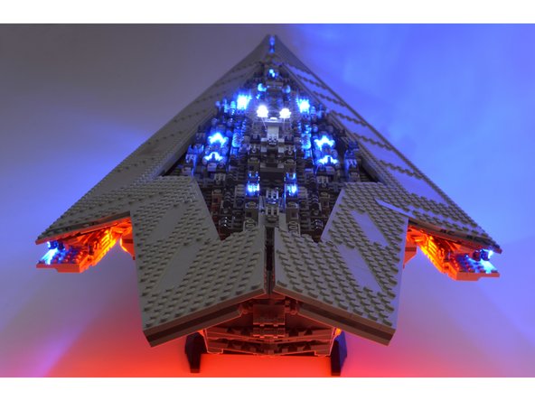
Enjoy your Super Star Destroyer! If you have any questions or run into any trouble, please contact us at support@brickstuff.com.
-


Attached Documents
