
Tools
Parts
Featured Document
-
-
There are several ways to read this guide:
-
Reading it on the web in your browser.
-
Downloading a PDF copy of the guide. You can do this by selecting "Download PDF" as shown by the red rectangle in the first photo. Click on the Options heading in the upper right corner of the screen (see the green rectangle).
-
In the "Dozuki" application, which is available for download from the Apple App Store and various Android and Google marketplaces.
-
If you view this guide in the Dozuki app, search for "Brickstuff" the first time you open the app, then select "Product Guides" from the categories listed under Brickstuff. Scroll down to find this guide.
-
You can also translate this guide into another language when viewing on the web. To do this, install a translator extension into your browser and use that extension/plug-in to translate the page. Using the main Google translate website (translate.google.com) does not work.
-
-
-
As shown in the first photo, it is very important to look at the color of the wires for the lights in this kit.
-
Lights with red and black wires can be connected to any adapter their plugs will fit into.
-
Lights with blue and white wires can ONLY be connected to either a BRANCH09X or BRANCH09XS adapter board. Connecting a light with blue and white wires to any other adapter board (including other adapters where the plugs fit) will destroy the light.
-
The second photo is a visual reference for the controllers and adapter boards included with your kit. You may want to print a copy to reference as you walk through the instructions. You can download a PDF copy of this illustration here.
-
Here are some other very important tips to keep in mind as you connect the parts in this kit:
-
Plugs connect to adapter boards and controllers only one way. Do not force plugs.
-
Do not remove plugs with tabs by pulling on the wire. Always use your fingernails or tweezers to remove plugs by pulling on the tabs of the plug, not the wires.
-
Many boards have connectors that face vertically (upward). Use extra care when connecting or disconnecting plugs to these connectors. Pulling or pushing sideways on any vertically-facing plug can cause the plug to come detached from its circuit board.
-
-
-
Note that this guide applies only to "Version 2" Disney Castle lighting kits, which include kits sold beginning with the November 2019 batch of orders.
-
If your kit is a "Version 2" kit, it will include a TRUNK08 master controller like the one shown in the photo for this step, and you can continue in this guide.
-
The TRUNK08 controller included with your kit may have slightly different plugs or parts than the ones shown in the photo. That is ok.
-
If your kit does not have a controller that looks like this, you have a "Version 1" kit and these instructions will not apply to you.
-
If you have a "Version 1" kit, you can download installation instructions here.
-
If you have a "Version 1" kit, we are looking into the possibility of creating an upgrade kit. We currently do not have a date set for release of this kit.
-
-
-
When connecting plugs, it is important to be able to tell the top of the plug from the bottom. The first photo in this step shows the top of two different types of plugs, and the second photo shows the bottoms.
-
Plugs will fit into connectors only one way. Do not force!
-
When removing plugs, to not pull from the wire. As shown in the third photo in this step, use your fingers to pinch the tabs on larger plugs and pull on the tabs to remove.
-
The connectors in this kit can hold plugs very tightly. Pulling on the wire instead of using the tabs on larger plugs will cause the wires to pull out. Once a wire pulls out from a plug, it cannot be repaired.
-
-
-
You will begin by installing lights on the lower section of your castle.
-
To prepare, carefully remove the top two sections of your castle as shown by the blue and red arrows in the first photo.
-
As shown in the second photo, remove the two rear torches and two knight statues. Removing these parts will make it easier to lay your castle on its side in future steps.
-
As shown in the third photo, you should now have the three sections of your castle separated.
-
You can set the middle and top sections aside. You will work on them later.
-
-
-
As shown in the first two photos, remove the two front torches from either side of the main castle door.
-
As shown in the second photo, separate the lower torch pieces.
-
As shown in the third photo, take the pink bag labeled "Exterior Lights: Lower Level Lights and Parts" out of the box labeled "Exterior Lights."
-
-
-
As shown by the red and blue arrows in the first photo, there are LED lights with two different lengths of wire included in the bag. You will use two LED lights with longer wires for the front torches.
-
As shown by the orange arrow in the second photo, carefully bend two LED lights at the end of their wires, so the round white portion (with the light) faces forward.
-
As shown in the third photo, feed the LED light wire through the hole in the round 1x1 gold plate.
-
-
-
As shown in the first photo, carefully re-insert the brown part into the bottom of the round gold plate.
-
You may need to use some force to insert the brown part. The LED light wires are strong enough to be squeezed between the brown and gold pieces.
-
As shown in the second photo, re-attach the top section of the torch.
-
As shown by the red arrow in the second photo, you may need to raise the center gold piece a little to allow the LED light to sit inside the torch.
-
As shown in the third photo, repeat this process for the second torch.
-
-
-
Next, you will test the two front torches to make sure the wires did not get cut during re-assembly of the torches. This is the first of several times that you will test the front torches.
-
As shown in the first photo, take the USB power cable from the box labeled "Remote Control and Power," connect it to a mains adapter or USB battery bank, and connect the Brickstuff power plug to the large connector on the BRANCH03/A3 adapter board.
-
The BRANCH03/A3 adapter board is included in the same bag as the LED lights.
-
Connect the two small plugs on the LED light wires to the two small connectors on the BRANCH03/A3 adapter board as shown in the second and third photos.
-
As shown in the third photo, both torches should light up.
-
In case one or more LED lights become damaged during installation and do not light up, there are three spare LED lights included in a bag labeled "Extra Parts," which is inside the box labeled "Remote Control and Power." You can use these extra lights to replace any lights that become damaged during installation.
-
If you use up the three extra lights included with your kit, you can purchase additional Warm White Pico LEDs from our website in either 2- or 10-packs.
-
After you have successfully tested the torches, you can disconnect them from the BRANCH03 adapter board.
-
-
-
As shown in the photos for this step, next you will remove sections from the front of the castle and the rockwork by the front door. This is to prepare for re-attaching the two front torches and hiding their wires.
-
-
-
Remove the remaining surrounding parts as shown in the photos for this step.
-
-
-
As shown in the first photo for this step, re-attach the first torch to the white pillar, then run its wire down the back center of the pillar as shown by the dotted blue lines.
-
It is important to make sure that the light wire runs down the center of the back of the pillar. This will allow the pillar to re-attach to the studs behind it without pinching the wire.
-
Re-attach the white pillar.
-
As shown in the second and third photos for this step, carefully run the light wire down the side of the light bluish gray plate next to the pillar and out toward the front of the castle.
-
It is important to run the wires between, not on top of, studs. This prevents the wires from becoming pinched or cut when parts are attached on top of them.
-
-
-
As shown in the photos for this step, begin carefully re-attaching the rock pieces you removed earlier.
-
Always make sure the wires underneath the pieces you re-attach are running between, not on top of, any studs.
-
As shown by the blue dotted lines and arrow in the third step, make sure the wire runs down the corner of the rock pieces as close to the back edges as possible.
-
-
-
As shown in the photos for this step, continue re-attaching the parts you removed earlier to fully hide the light wires.
-
Repeat this same process for the second front torch.
-
Several of the parts in this step can be difficult to re-attach, since they press down on the LED light wires. If a part will not snap back down onto the part below it, loosen the wire underneath the brick a bit to allow more slack.
-
-
-
You should now have both front torches re-attached with their wires hidden beneath the rock and stair pieces as outlined in the previous steps.
-
As shown in the second photo for this step, connect the lights to the BRANCH03/A3 adapter board a second time to test them. It is important to make sure both lights still work and that no wires became pinched of clipped during installation.
-
If any wires become hot to the touch during testing, this means they have become pinched and are causing an electrical "short circuit." Disconnect immediately and replace the affected light.
-
In case one or more LED lights become damaged during installation and do not light up, there are three spare LED lights included in a bag labeled "Extra Parts," which is inside the box labeled "Remote Control and Power." You can use these extra lights to replace any lights that become damaged during installation.
-
-
-
As shown in the photos for this step, re-attach the white railings on either side of the front steps.
-
-
-
Next, you will remove several tiles in the interior castle floor to make room for passing power and control cables later. In order to access the floor tiles, you need to temporarily remove from pieces from the front exterior of the castle.
-
As shown in the first two photos for this step, remove the large slope from the left front tower next to the door.
-
As shown in the third photo, remove the rockwork pieces that are holding the front castle wall in place.
-
-
-
As shown in the first photo for this step, you should now have the yellow and tan pieces visible at the base of the castle wall.
-
As shown by the red arrows in the second photo, gently lift the castle wall so it will pass over the studs in the floor pieces.
-
As shown by the green arrows in the third photo, carefully slide the castle wall out a small amount. You will feel when it stops and cannot swing out any further.
-
-
-
Turn your castle around so you can access the inside.
-
The photos in these steps show the knight statues mounted in the castle, but you will have removed these from your castle at the beginning of the installation process.
-
As shown in the photos for this step, remove the 2x2 dark tan tile and use a brick separator to remove the 2x4 dark tan plate.
-
-
-
As shown in the first photo for this step, use a brick separator to remove the two long dark tan tiles from the castle floor.
-
As shown in the second and third photos, take the 2x2 tile you removed in the previous step and attach it to the top of the open space created by removing the two long tiles as shown by the green square in the third photo.
-
-
-
As shown in the first and second photos for this step, re-attach the two long dark tan tiles you removed in the last step so they leave a gap in the floor.
-
As shown by the blue rectangle in the third photo, re-attach the dark tan 2x4 plate you removed earlier on top of the two long tiles.
-
As shown by the green arrows in the third step, this should leave a gap in the castle floor the same size as a 2x3 plate or tile.
-
-
-
As shown by the green arrows in the first photo for this step, carefully slide the outer castle wall back into place.
-
Rotate your castle so you are looking at the front again.
-
As shown in the third photo, re-attach the rock pieces you removed earlier. These will hold the castle wall in its proper place one again.
-
-
-
As shown in the first photo for this step, you should now have all rockwork pieces re-attached.
-
As shown in the second and third photos, re-attach the long slope to the outside of the castle tower.
-
-
-
Now you will gently lay your castle on its side, to provide access to the underside.
-
Before tilting your castle backward, make sure you have a flat surface behind the castle that is large enough for the castle to fit when on its side. It is also a good idea to place a blanket or other soft towel behind the castle as you tilt it backward.
-
As shown in the photos for this step, carefully and slowly tilt your castle backward, supporting the back with one hand.
-
As shown in the second photo, your castle show now be sitting on its side with the underside visible and accessible.
-
The blue arrows in the second photo show the locations where the wires from the two front torch lights should be sticking out from under the top rock pieces.
-
-
-
For the next steps, you will use the parts contained in the bag labeled "Exterior Lights: Lower Level Lights and Parts" as shown in the first photo.
-
Begin by taking the eight round "boat stud" parts out of the bag as shown in the second photo.
-
The boar studs in your kit may be a different color than those shown in the photo.
-
As shown by the red circles in the third photo, attach the eight "boat stud" parts to the bottom of the castle so the castle will be raised a bit and still be balanced when on a flat surface.
-
The "boat stud" parts make it easier to move your castle and also allow the spotlights to better remain attached to the castle when moving.
-
-
-
The "Lower Level Lights and Parts" bag contains several adapter boards, two of which have similar names: BRANCH09X and BRANCH09XS. For this step, you want to use the BRANCH09XS adapter as shown by the red rectangle in the first photo.
-
You will also use the long adapter board labeled BRANCH17 on the back. The third photo shows the two adapters needed: one BRANCH17 and one BRANCH09XS.
-
-
-
Also inside the "Lower Level Lights and Parts" bag will be a short (2.5"/6.3cm) red wire with plugs on both end as shown in the first photo.
-
As shown by the orange rectangle in the second photo, connect one end of the red wire to the large plug on the BRANCH09XS adapter board labeled "OUT".
-
For the lights to function properly, it is critical that you connect the plugs in the correct order. Do not connect anything to the "IN" plug on the BRANCH09XS yet.
-
As shown by the yellow square in the third photo, connect the other end of the red wire to the plug on the BRANCH17 adapter board labeled "IN".
-
You should now have the BRANCH09XS and BRANCH17 adapter boards connected to each other.
-
-
-
Next you will connect a long 3-wire cable to the "IN" plug on the BRANCH09XS adapter. Note, this wire may be red or black in your kit.
-
Inside the "Lower Level Lights and Parts" bag will be two 24"/60.9cm cables as shown in the first photo.
-
Depending on when your kit was manufactured, one of the long wires may be red.
-
As shown in the second photo, one of the wires has a 3-wire plug (the green checkmark) and the other has a 2-wire pliug (red "X"). You will use the 3-wire plug in this step. Do not use the cable with the 2-wire plug.
-
As shown by the purple rectangle in the third photo, connect one end of the 3-wire plug to the "IN" connector on the BRANCH09XS adapter board.
-
Even though it is physically possible to insert a 2-wire plug into a 3-wire socket, doing so will cause a short circuit. Never connect a 2-wire plug to a 3-wire socket.
-
-
-
Inside the box labeled "Main Control Board and Spotlights," there is a bag labeled "Warm White Spotlights.
-
The warm white spotlights bag contains eight spotlights. You will mount four of them on the lower castle level.
-
As shown by the blue circles in the second photo, attach the warm white spotlights to the castle base, spacing them evenly.
-
As shown in the third photo, connect the wires for the four warm white spotlights to the plugs labeled 1-4 on the BRANCH09XS adapter board.
-
It does not matter which spotlight you connect to which specific plug on the BRANCH09XS adapter, as long as you only use plugs 1-4 on the BRANCH09XS adapter. Leave plugs 5 and 6 open for now.
-
-
-
As shown in the photos for this step, connect the wires from the two front door torches to plugs 5 and 6 on the BRANCH09XS adapter board.
-
-
-
Also inside the box labeled "Main Control Board and Spotlights," there is a bag labeled "Color-Changing Spotlights." There are nine spotlights in this bag-- you will use four of them for this step.
-
As shown in the second and third photos, remove four color-changing spotlights from the bag and mount them along the castle base nest to the warm white spotlights (see the red arrows in the third photo).
-
-
-
As shown in the photos for this step, connect the four color-changing spotlights to plugs 1-4 on the BRANCH17 adapter board.
-
Leave plug 5 (labeled RGB5 on the BRANCH17 adapter board) empty. In order for all spotlights to work, they must be connected to plugs 1-4 with no open plugs left in between.
-
You will leave plug RGB5 empty, and you will also leave the "OUT" plug on the BRANCH17 adapter board empty.
-
-
-
NOTE: Depending on when your kit was made, you may have a BRANCH17 adapter that looks different from the one in these photos. Your BRANCH17 adapter may have side-facing connectors instead of top-facing connectors as shown in the photos.
-
Attach two small sticky squares from the "Lower Level Lights and Parts" bag to the area under the castle by the 4x4 red plate as shown.
-
Attach the sticky squares as shown so they are recessed under the base. The BRANCH17 adapter needs to fit under the base and not scrape on the flt surface the castle is placed on.
-
As shown in the second photo, mount the BRANCH17 adapter so it is held in place by the small sticky squares.
-
-
-
Attach one large sticky square from the "Lower Level Lights and Parts" bag next to the BRANCH17 adapter board, then attach the BRANCH09XS adapter board as shown in the second photo.
-
34: Note that if your kit has a BRANCH17 adapter with side-facing connectors, you will need to mount the BRANCH09XS adapter in a reversed position so its "OUT" cable will reach the "IN" connector on the BRANCH17.
-
As shown in the third photo, you should now have the BRANCH17 and BRANCH09XS adapter boards mounted under the castle so their plugs do not stick out below the bottom plates of the castle base.
-
-
-
Now you will clean up the wiring underneath the castle and hide any excess wire.
-
As shown in the first photo, you can use the "boat stud" parts to hold the spotlight wires in place. Just make sure all wires run between, not on top of, any studs.
-
As shown by the blue arrows in the second photo, you can further secure spotlight wires by removing plates from the base of the castle, carefully passing wires between (not on top of) studs, an replacing the plates.
-
As you clean up spotlight wires, you can coil long sections of wire and feed them into the gaps under the castle base next to the BRANCH17 and BRANCH09XS adapter boards.
-
In the end, you want to make sure that all spotlight wires are neat and organized, and that no excess wire hangs below the castle base to scrape on the surface you will display your castle on.
-
As shown in the third photo, when you are finished cleaning up the spotlight wires, you should have a neat arrangement with all excess wire tucked into the castle base. The only wire left hanging should be the black 24"/60.9cm wire connected to the "IN" plug on the BRANCH09XS adapter board.
-
-
-
As shown in the photos for this step, carefully take the 3-wire cable that is connected to the BRANCH09XS adapter board and feed it through the hole in the bottom of the castle floor that you made earlier.
-
As shown in the second photo, you can remove pieces of the castle base to help hold the wire in place. Just make sure you run the wire between, and not on top of, any studs.
-
The blue arrows in the third photo show the hole through which you will feed the 3-wire cable. Pass it all the way through so there is no slack left underneath the castle base.
-
Remember that your 3-wire cable may be black or red, depending on when your castle light kit was manufactured.
-
-
-
As shown in the first photo for this step, take the black 24"/60.9cm 2-wire cable from the "Lower Level Lights and Parts" bag, and connect it to the BRANCH04 adapter (also contained in the "Lower Level Lights and Parts" bag).
-
It does not matter which plug on the BRANCH04 adapter board you connect the wire to.
-
This time, you will be using the 2-wire cable, not the 3-wire cable you should have already fed through the base of the castle.
-
As shown by the orange arrows in the second photo, feed the 2-wire cable through the hole in the castle floor. This is the same hole you fed the 3-wire cable through in the previous step.
-
Feed the end of the cable NOT connected to the BRANCH04 adapter board.
-
As shown in the third photo, secure the 2-wire cable to the underside of the castle base using one of the "boat stud" pieces.
-
Before securing the cable, make sure that approximately 6"/15cm of the wire extends out from the bottom of the castle. This is where you will connect your main power supply later, so it is important that the cable be accessible when the castle is upright.
-
-
-
As shown in the first photo for this step, carefully tilt your castle forward, making sure no wires, plugs, or adapter boards stick out far enough to scrape on the surface you place the castle on.
-
The second and third photos show the 2-wire cable connected to the BRANCH04 adapter board, and the red line in the third photo shows the approximate length of cable that should extend out from under the castle base to allow the main power supply to be connected.
-
-
-
You should now have two cables coming into the main castle interior through the floor: one 2-wire cable (black) and one 3-wire cable (either red or black).
-
As shown in the first photo, use a brick separator to remove the tan 2x4 LEGO plate you mounted earlier, and use the 2x4 plate to hold the two wires in place as shown in the second and third photos.
-
When securing wires, make sure to pass both wires between studs, not on top of them. If a wire passes over the top of a stud and has a plate attached on top, the wire can become damaged.
-
You should now have both wires held firmly in place, and the hole in your castle floor should be mostly covered by the 2x4 tan plate as shown.
-
-
-
As shown in the first photo for this step, remove the large brown rectangle piece from the castle interior upper floor.
-
As shown by the green arrows in the second photo, wrap the two black wires once around the tan pillar under the brown floor pieces, being careful to wrap the wires over the dark bluish gray tile and not over any studs.
-
Replace the large brown floor piece.
-
Run the two wires under the brown floor along the edge just behind the outer walls.
-
As shown in the third photo, you should now have both wires extending toward the center of the castle.
-
-
-
Now you will prepare to mount a warm white Pico LED light behind the exterior clock above the main castle door.
-
As shown in the first and second photos, remove the LED light with 6"/15.2cm wire and also the transparent round 1x1 LEGO plate from the "Lower Level Lights and Parts" bag.
-
-
-
As shown in the first photo for this step, remove the clock and the red and yellow LEGO parts holding it in place.
-
As shown in the second photo, separate the clock, 2x2 red LEGO jumper plate, and 2x2 yellow brick.
-
Mount the warm white Pico LED light in the center of the 2x2 yellow LEGO brick, and carefully place the 1x1 transparent round LEGO plate on top of the LED light.
-
You will no longer need the red jumper plate, and can set this aside.
-
As shown in the third photo, remove the roof section above the clock.
-
-
-
As shown in the first photo, re-mount the clock face into the roof section, routing the LED light wire under the yellow LEGO brick.
-
Re-attach the clock and roof section. The clock LED light wire should stick out the back of the section behind the clock.
-
When re-attaching the clock and re-assembling the roof sections above it, make sure the LED light wire passes back and runs between, not on top of, studs.
-
The green rectangle in the second photo shows the clock light wire passing out the back of the clock.
-
The third photo shows the clock LED light wire passing out the back of the clock assembly.
-
-
-
Next you will mount the remote control receiver to the back of the castle.
-
Inside the box labeled "Remote Control and Power," remove the bag with the 4-button remote control and receiver circuit board.
-
As shown in the second photo, take a large sticky square and attach it to the back of the remote receiver.
-
There is a small white button on the front of the receiver. Attach the sticky square to the side of the receiver opposite the button.
-
As shown in the third photo, mount the receiver in the recessed area behind the clock. Make sure the white button is visible as shown by the red square in the third photo.
-
The antenna on the receiver is the black coiled wire. You can bend the wire as shown in the third photo, but do not un-coil the wire.
-
-
-
As shown in the first and second photos, take the four Velcro dots from the "Lower Level Lights and Parts" bag and stick them on the back section of the castle tower as shown in the second photo.
-
Remove the TRUNK08 master controller board from the box labeled "Main Control Board and Spotlights," and mount the board to the four Velcro dots as shown in the third photo. Attaching the board with the Velcro dots will make it possible to remove and re-attach the board later if needed.
-
Make sure the two remote control receiver wires pass above, not under, the master controller board as shown in the third photo.
-
-
-
As shown by the orange arrow in the first photo for this step, connect the small 4-wire connector from the remote control receiver to the plug labeled "REMOTE" on the TRUNK08 master controller.
-
The plug will fit only one way. Do not force. Use your fingernail to press the plug in. You will feel a soft "click" when the plug is inserted all the way.
-
As shown by the green arrow in the second photo, connect the larger 2-wire connector from the remote control receiver to one of the three POWER plugs on the BRANCH08 master controller.
-
It does not matter which of the three POWER plugs you connect the receiver to.
-
After you have connected the two remote receiver wires to the TRUNK08 master controller, tuck the excess wires into the space behind the TRUNK08 master controller so there are no wires hanging out.
-
-
-
As shown in the photos for this step, take the black 2-wire power cable you ran from under the castle in Step 40 and connect it to one of the POWER plugs on the TRUNK08 master controller.
-
Make sure you connect the 2-wire plug, not the 3-wire plug. You will connect the 3-wire plug in a later step.
-
-
-
Next you will prepare the light strip that mounts behind the center decorative panel.
-
From the "Lower Level Lights and Parts" bag, remove the 6"/15.2cm black connecting cable, the warm white light strip, and the two black LEGO slopes as shown in the first photo.
-
As shown in the second photo, connect one end of the black cable to one of the plugs on the light strip.
-
It does not matter which end of the light strip you connect the wire to.
-
As shown by the two orange arrows in the third photo, attach the two black slope pieces behind the decorative panel so they are sloped toward the front.
-
You may need to remove the brown plate in order to attach the two black slopes.
-
-
-
As shown in the first two photos, remove the self-adhesive backing from the light strip and mount the strip on top of the two black slopes so the light strip faces forward to the area behind the white panel as shown.
-
As shown by the green arrow in the third photo, connect the other end of the light strip cable to the OUT1 plug on the TRUNK08 master controller.
-
-
-
Next you will mount four warm white Pico LED lights, one inside each of the main towers on the castle wall.
-
As shown in the photos for this step, remove the top and side pieces from the tower on the left in preparation for mounting the first light.
-
-
-
You should still have four warm white Pico LED lights with 12"/30.4cm wires inside the "Lower Level Lights and Parts" bag. Remove those lights, and also remove four small sticky squares from the bag.
-
As shown in the second photo, attach one sticky square to the back of each LED light.
-
As shown by the orange circle in the third photo, stick the LED light in the center of the tower so it is pointing upward, and so its wire runs toward the back of the castle.
-
-
-
As shown in the photos for this step, carefully re-assemble the first tower, making sure the LED light wire runs between, not on top of, any studs.
-
-
-
As shown in the photos for this step, remove the top and rear parts from the second tower so you can mount the second LED light.
-
-
-
As shown in the first photo, carefully re-attach the back portion of the tower, making sure the LED light wire runs between and not on top of studs.
-
Because the LED light wire bends so tightly here, take extra care to make sure it does not become pinched.
-
Re-attach the top of the tower.
-
As shown in the second and third photos, remove the light bluish gray side piece from the tower, tuck the LED light wire underneath, then re-attach the piece. This should hold the LED light wire in place.
-
Repeat this process for the remaining two towers, so all four lights are mounted, one inside each tower.
-
-
-
Remove the BRANCH09X adapter and the 1.5"/3.8cm red wire from the "Lower Level Lights and Parts" bag.
-
As shown by the orange rectangle in the first photo, connect one end of the red wire to the plug on the BRANCH09X adapter labeled INPUT.
-
For proper operation of your lights, it is critical that you connect the red wire to the INPUT connector.
-
As shown in the second and third photos, take the 24"/60.9cm 3-wire cable you connected to the castle's base spotlights earlier and connect it to the plug labeled OUTPUT on the BRANCH09X adapter board as shown by the blue arrow in the third photo.
-
Depending on when your kit was manufactured, your 24"/60.9cm 3-wire cable may be either black or red.
-
-
-
As shown by the green arrow in the first photo for this step, connect the other end of the red 1.5"/3,8cm 3-wire cable to the plug on the TRUNK08 master controller labeled "PIXEL."
-
As shown by the orange square in the second photo, attach a large sticky square to the back castle wall area to the left of the TRUNK08 master controller.
-
Attach the BRANCH09X adapter board to the back castle wall with the large sticky square.
-
As shown by the green arrow in the third photo, connect the LED light wire from the castle clock to the plug labeled "1" on the BRANCH09X adapter board.
-
For proper operation, it is critical that you connect the lights to the specific ports on the BRANCH09X adapter as directed.
-
-
-
As shown by the orange arrows in the first photo, connect the four tower lights to plugs #2, #3, #4, and #5 on the BRANCH09X adapter board.
-
You can connect the four tower lights in any order as long as you only use plugs 2-5.
-
As shown in the second and third photos for this step, you should now have the four tower lights connected to the BRANCH09X adapter. You will have excess wire and you can coil the extra wire using a pencil or tweezers so the wiring is neat.
-
-
-
You should still have four spotlights left in the "Warm White Spotlights" bag. Take these out and mount them along the inner back castle wall so they are approximately evenly spaced.
-
You can use a variety of techniques to mount and angle the spotlights. There are dark bluish gray plates and jumper plates in the "Lower Level Lights and Parts" bag that you can use to attach and angle the lights.
-
Make sure the lights face upward toward where the inner castle wall will be.
-
As shown by the green arrow in the second photo, you can detach the round gold piece on the end of the spotlight arm, turn it backwards, then re-attach if you want to be able to adjust the light on a different angle.
-
Once you have mounted all four spotlights, connect them to plugs #6, #7, #8, and #9 on the BRANCH09X adapter board as shown by the orange arrows in the third photo.
-
It does not matter which specific order you connect the spotlights in, as long as you only use plugs 6-9.
-
-
-
After mounting and connecting the four warm white spotlights, they should be distributed along the back of the castle wall approximately like the lights in the photo (see the blue arrows).
-
The exact distribution is not critical. You can arrange the lights as you like.
-
After connecting the spotlights to the BRANCH09X adapter board, you will have excess wire. You can use a pencil or tweezers to coil up the excess wire so the layout is neat.
-
-
-
Inside the "Lower Level Lights and Parts" bag, there will be a custom cable with connectors on each end like the ones shown in the first photo. One end will have a small 3-wire plug and the other end will have a large 3-wire plug.
-
Also inside the "Lower Level Lights and Parts" bag, there will be a long adapter board labeled BRANCH17 on the back. As shown by the orange rectangle in the second photo, connect the large end of the cable to the plug labeled "IN" on the BRANCH17 adapter board.
-
In order for the lights to operate correctly, it is important that you connect the plug to the "IN" connector on the BRANCH17 adapter.
-
As shown by the green rectangle in the third photo, connect the other end of the cable (the end with the small connector) to the plug labeled "SENS1" on the TRUNK08 master controller.
-
Be careful when connecting the wire, as the SENS1 plug is small and can break off the TRUNK08 board if you use too much force or if you pull to either side when inserting the plug.
-
-
-
You should still have five color-changing spotlights in "Color-Changing Spotlights" bag. Remove them and mount them along the inner castle wall next to the warm white spotlights you mounted earlier.
-
The second and third photos in this step show some of the ways you can adjust the mounting or the spotlights to fit them all in.
-
You can use some of the dark bluish gray plates and jumper plates from the "Lower Level Lights and Parts" bag to help in mounting the color-changing spotlights.
-
-
-
After you have mounted the five color-changing spotlights, you can connect the five wires from the spotlights to the five small plugs on the BRANCH17 adapter board as shown in the second photo.
-
It does not matter in which order you connect the spotlights, as long as all five of the small plugs on the BRANCH17 adapter board are filled.
-
As shown in the third photo, you can use two 1x2 dark bluish gray plates (from the "Lower Level Lights and Parts" bag) to secure the BRANCH17 adapter board to the castle floor, just behind the warm white light strip.
-
-
-
By this time you will have many light wires in the back of the castle-- as shown in the first photo, there will be a lot of excess wire.
-
Using a pencil or tweezers, you can carefully coil up the extra wire so the appearance is cleaner, as shown in the second photo.
-
Make sure no wires hang over into the area where the middle section of the castle fits onto the bottom section (see the area framed by the red lines in the second photo). If any wires hang into this area, the middle section of the castle will not securely attach and could fall over.
-
-
-
Also in the "Lower Level Lights and Parts" bag, there will be another custom cable with ends like the ones shown in the first photo. One end will have a small 3-wire connector and the other end will have a small black connector with a white dot on one side.
-
As shown by the orange rectangle in the second photo, connect the end of the cable with the small connector to the "SENS2" plug on the TRUNK08 master controller.
-
Be careful when connecting the wire, as the SENS2 plug is small and can break off the TRUNK08 board if you use too much force or if you pull to either side when inserting the plug.
-
As shown by the orange arrow in the third photo, run the cable under the brown floor sections and out toward the back of the castle. As shown in the photo, you can use one of the dark bluish gray tiles to hold the cable in place.
-
The black plug needs to be accessible even when the middle and upper sections of the castle are attached to the bottom section.
-
When placing tiles or other parts on top of wires, make sure the wires run between, not on top of, studs. If a LEGO part is placed on top of a wire that runs on top of a stud beneath, the wire can become pinched or cut.
-
-
-
If you purchased the optional sound module add-on, you might want to skip ahead to Step 143 and install that module now, before moving on to the upper castle sections.
-
As shown in the first photo for this step, you can replace the two knight statues.
-
If you did not purchase the interior lighting kit, you can also replace the two interior torches.
-
If you did not purchase the interior lighting kit, you can jump ahead to STEP 72.
-
If you did purchase the interior lighting kit, do not replace the interior torches. Move to the next step.
-
-
-
NOTE: This step applies only to those who purchased the interior lighting kit. If you did not purchase the interior light kit, you can skip to STEP 72.
-
Inside the box labeled "Interior Lights," remove the two pre-lit torches as shown in the first photo.
-
As shown in the second photo, carefully remove the center section of one of the columns behind the torch wall mounts.
-
As shown by the yellow arrows in the third photo, attach one of the torches to the wall mount, and make sure the light wire runs to the back side of the tan pillar.
-
-
-
As shown in the first photo, carefully re-attach the pillar behind the torch.
-
When re-attaching the pillar, make sure the light wire runs between, not on top of, any studs.
-
Repeat for the second torch. When complete, you should have both torches mounted and wires extending out the back of the pillars as shown in the second photo.
-
As shown in the third photo, you can remove sections of the dark bluish gray tiles and jumper plates to gather the torch light wires and run them back toward the TRUNK08 master controller.
-
-
-
As shown in the first and second photos for this step, continue running the light wires from each torch back toward the TRUNK08 master controller.
-
As shown in the second photo, you can remove some of the brown tiles to allow the torch light wires to pass underneath.
-
Make sure all light wires run between, not on top of, studs.
-
As shown in the third photo, when you are finished routing the torch light wires, they should be within reach of the TRUNK08 master controller.
-
-
-
As shown by the orange arrows, connect the two torches to outputs OUT3 and OUT4 on the TRUNK08 master controller.
-
It does not matter which output each torch is connected to, as long as you use OUT3 and OUT4.
-
-
-
Inside the box labeled "Chandelier," there is a pre-lit chandelier with eight lights and one connecting wire as shown in the first photo.
-
As shown in the second photo, remove your un-lit chandelier from its mount and transfer the parts (top mount, lower gold round plate) over to the pre-lit chandelier.
-
Mount the pre-lit chandelier under the brown floor sections in the same place as the original.
-
As shown in the third photo, remove the large center brown plate to make room for the chandelier light wire.
-
-
-
Run the chandelier light wire back toward the TRUNK08 master controller as shown in the first photo.
-
As shown by the orange arrow in the second photo, connect the chandelier light wire to the OUT2 connector on the TRUNK08 master controller.
-
Replace the large brown floor plate, making sure any wires run between, not on top of, studs.
-
-
-
As shown in the photo for this step, you may choose to re-locate the wire with the black plug so it feeds to the side of the left torch.
-
The important thing is to make sure the black plug is accessible even when the middle and upper sections of the castle are attached.
-
Congratulations! You have now completed installation of the lower level lights. Before moving on, now is a good time to take a break.
-
-
-
After finishing work on the lower section of the castle, you will work on the upper section next. You will work on the middle section last.
-
As shown in the second photo, carefully remove the top section of the upper tower so the flat white plates have separated (blue arrows).
-
-
-
For these next steps, you will use parts from the bag labeled "Upper Level Lights and Parts," which is inside the Exterior Lights box.
-
There are warm white Pico LED lights with several different length wires in the bag. Remove the two LED lights with 12"/30.4cm wires as shown in the second photo.
-
-
-
As shown in the first photo for this step, bend the wire on one of the lights and place it down inside the small ceiling area.
-
As shown in the second and third photos, take one of the clear "boat stud" parts from the "Upper Level Lights and Parts" bag, and use it to hold the ceiling light in place.
-
When attaching the "boat stud," make sure the LED light wires run between, not on top of, any studs.
-
-
-
As shown by the red arrow in the first photo, use a second "boat stud" piece to secure the second ceiling light. Make sure to position the light exactly as shown in the photo.
-
As shown in the second and third photos, carefully re-attach the tower roof. After the roof has been attached, the two LED light wires should pass out toward the back of the tower as shown in the third photo.
-
-
-
As shown in the first photo for this step, carefully loosen the left pillar.
-
As shown in the second photo, wrap the two LED light wires around the pillar, then re-attach it to the ceiling.
-
Remove the mirror from the mirror room.
-
As shown by the red arrows in the third photo, use the white 1x2 LEGO plate contained inside the "Upper Level Lights and Parts" bag to hold the two LED light wires to the ceiling of the mirror room.
-
When attaching the white plate, make sure the two LED light wires pass between, not on top of, any studs.
-
-
-
As shown in the first photo for this step, remove the six 2x2 dark red LEGO jumper plates from the floor of the mirror room.
-
Run the two light wires through the circular hole in the floor of the mirror room as shown by the red circle in the second photo.
-
As shown by the orange circle in the third photo, the two light wires should extend down to the lowest level of the top tower through the hole in the ceiling.
-
-
-
As shown in the first photo, remove the BRANCH09X adapter board from the "Upper Level Lights and Parts" bag.
-
Take the two LED light wires and connect them to plugs #1 and #2 on the BRANCH09X adapter board as shown by the orange arrows in the second photo.
-
It does not matter which light you connect to plug #1 and which light you connect to plug #2.
-
-
-
As shown in the first photo for this step, take the warm white Pico LED light with 3"/7.6cm wire out of the "Upper Level Lights and Parts" bag. This will be the LED light with the shortest wire in the bag.
-
As shown by the red circle in the second photo, use another clear "boat stud" piece to hold the light in place on the ceiling, just next to the hole where the two wires pass through.
-
Make sure you do not cover the hole in the ceiling with the "boat stud" piece.
-
As shown by the orange arrow in the third photo, connect the ceiling light to plug #3 on the BRANCH09X adapter board.
-
-
-
You should have two warm white Pico LED lights with 6"/15.2cm wires inside the "Upper Level Lights and Parts" bag as shown in the first photo.
-
As shown in the second photo, remove the fireworks launcher and two white pillars from the outside of the tower front.
-
As shown by the two blue arrows in the third photo, use two small sticky squares to attach the lights to the front of the tower floor. Carefully replace the two white columns, making sure the two LED light wires pass between, not on top of, any studs.
-
-
-
As shown by the two blue arrows in the first photo, route the wires from the two LED lights back into the interior of the tower.
-
As shown in the second photo, re-attach the fireworks launcher, making sure the wires underneath pass between, not on top of, any studs.
-
As shown by the two orange arrows in the third photo, connect the two LED light wires to plugs #4 and #5 on the BRANCH09X adapter board.
-
-
-
Inside the "Upper Level Lights and Parts" bag, there will be a short cable with two different connectors as shown in the first photo. One connector is a large 3-wire white plug and the other is a smaller black connector with gold pins and a white dot on one side.
-
As shown by the orange rectangle in the second photo, connect the large white connector to the INPUT plug on the BRANCH09X adapter board.
-
In order for the lights to work properly, the wire must be connected to the INPUT plug.
-
-
-
As shown in the photos for this step, use a large sticky square to mount the BRANCH09X adapter board to the ceiling of the lower room.
-
-
-
As shown in the first photo, remove the dark red parts and treasure chest from the floor of the lower tower room.
-
As shown in the second photo, pass the black connector through the hole in the floor, so the cable extends under the bottom of the floor as shown in the third photo.
-
The red circles in the second and third photos show the hole through which the wire passes.
-
-
-
As shown in the first photo, coil up any excess wire in the lower room using a pencil or tweezers.
-
As shown in the second photo, re-attach the floor parts in the lower room, being careful to install them one stud forward from where they were originally installed.
-
It is necessary to install everything one stud forward to keep open the hole in the floor through which the wire passes.
-
The red circle in the third photo shows how the wire should pass through the hole in the floor after you have re-attached the parts one stud forward from their original location.
-
Re-attach the treasure chest.
-
NOTE: The next three steps apply only to those who purchased the interior lighting kit. If you did not purchase the interior lighting kit, you can skip to STEP 90.
-
-
-
NOTE: This step and the next two steps apply only to those who purchased the interior lighting kit. If you did not purchase the interior lighting kit, you can skip to STEP 90.
-
Those of you who purchased the interior lighting kit will have a bag inside the Interior Lights box that is labeled 'Upper Level Interior Lights and Parts." Inside that bag will be three Pico LED lights: one warm white light, one blue light, and one red light.
-
As shown by the yellow arrow in the first photo, you can tell the warm white light because it has a white background board, while the red and blue lights have black boards.
-
It is not important which light is the red light and which light is the blue. The important thing is to be able to tell these two apart from the warm white light.
-
As shown in the second photo, take three sticky squares from the "Upper Level Interior Lights and Parts" bag and stick them to the back of each Pico LED light.
-
As shown in the third photo, stick the red and blue lights to the red "boat stud" on the back of the mirror so their wires run down toward the bottom of the mirror.
-
it does not matter which color light you mount on which side of the mirror back. The important thing is not to mount the warm white light (with the white board) to the back of the mirror.
-
-
-
As shown by the blue circle in the first photo, take the warm white Pico LED light (with the white board) and use the last small sticky square from the "Upper Level Interior Lights and Parts" bag to attach it to the white 1x2 LEGO plate on the ceiling of the mirror room.
-
As shown by the red circle in the second photo, pass the wire from the warm white light down through the hole in the floor of the mirror room.
-
As shown by the orange arrow in the third photo, connect the warm white LED light wire from the mirror room to plug #6 on the BRANCH09X adapter board.
-
-
-
As shown by the orange arrow in the first photo, wrap the two mirror light wires around the base of the mirror once, then pass the wires through the hole in the floor as shown by the red circle.
-
As shown in the second photo, re-attach the mirror.
-
As shown by the orange arrows in the third photo, connect the two mirror lights to plugs #7 and #8 on the BRANCH09X adapter board.
-
It does not matter which mirror light you connect to plug #7 and which light you connect to plug #8.
-
Note that plug #9 on the BRANCH09X adapter board will remain empty. No light should be connected to plug #9.
-
Use a pencil or tweezers to coil any excess wire from the lights in the mirror room.
-
-
-
As shown in the first photo, re-attach the dark red 2x2 LEGO jumper plates to the floor of the mirror room. Note that you will attach the jumper plates one stud forward from the back wall, to allow room for the light wires to pass to the room below.
-
Because you are attaching the jumper plates one stud forward from the back wall, you will have two extra jumpers as shown in the first photo. You can set these aside.
-
Once re-assembled, your setup should look like the second photo. The short wire with the black connecting plug should extend below the lower floor of the tower and all parts should be replaced.
-
Congratulations! You have now completed installation of the upper level lights. Before moving on, now is a good time to take a break.
-
-
-
Now you will begin installing lights in the middle section of the castle.
-
This is the last and also the most difficult part of the installation, so make sure to give yourself extra time to complete this section.
-
You have several options for installing the middle section lights:
-
If you did not purchase the interior light kit, you can choose to complete the installation of the middle section exterior lights without hiding the BRANCH09X adapter board, which will save considerable time but will also result in a messier interior.
-
If you purchased the interior light kit but prefer not to complete the disassembly in the steps ahead, you can still install the interior lights, but you will not have a glowing stove and you will have a messier setup in the kitchen.
-
If you purchased the interior light kit and are willing to do the disassembly outlined in the steps ahead, you will have a glowing stove light and also a clean installation, but there will be significant extra work involved.
-
Note that the photos and steps in this guide assume you will proceed with the disassembly option, so if you choose not to undertake this work, additional notes will be included describing-- but not showing with pictures-- how to proceed.
-
Before making a decision about which approach you want to take for your castle, we recommend scrolling through the following steps first before beginning, so you can see the amount of work involved and so you can make an informed decision.
-
-
-
If you chose not to complete the disassembly of the front of the castle, you can skip ahead to STEP 94.
-
before beginning, make sure you have a brick separator handy, and also make sure you have the original LEGO instruction book available in case you need help re-constructing the middle section later.
-
As shown in the photos for this step, use a brick separator to begin disassembling the front section of the castle behind the kitchen stove.
-
Make sure to remove all parts shown. Some of the parts may be difficult to remove, and you may need to apply upward pressure with the brick separator in order to get them free.
-
-
-
Continue disassembling the section behind the kitchen stove as shown.
-
As shown by the blue arrows in the second photo, make sure to remove the two light brown bricks from the oven wall.
-
The third photo shows how the results should look after disassembly is complete, as viewed from inside the kitchen.
-
-
-
For the following steps, you will use the parts in the bag labeled "Exterior Lights: Middle Level Lights and Parts."
-
As shown in the second photo, there is a special wire inside the "Middle Level Lights and Parts" bag that has a large white plug on one end and a small black plug with gold pins and a white dot on the other end.
-
There are two special wires inside the bag, both with white plugs on one end and black plugs on the other end. For this step, make sure you are using the wire that has the black plug with gold pins as shown by the yellow circle in the second photo (the "male" version of the plug).
-
Also inside the bag, there will be another BRANCH09X adapter board.
-
As shown by the orange rectangle in the third photo, connect the white end of the wire to the plug on the BRANCH09X adapter board labeled INPUT.
-
For the lights to operate properly, the plug must be connected to the INPUT connector.
-
-
-
Now you will pass the black end of the connecting cable through the hole in the kitchen floor, as shown by the red circle in the first photo.
-
The second photo shows the wire after the black connector end has been passed through the hole in the floor.
-
Leave a portion of the cable hanging under the castle section as shown by the blue arrow in the third photo.
-
If you choose not to complete the disassembly steps, you will have your BRANCH09X adapter board sitting loose in the kitchen and you will not be able to pass the wire down through the hole in the floor (since this will be covered by the stove).
-
-
-
Inside the "Middle Level Lights and Parts" bag, there are three warm white Pico LED lights with 12"/30.4cm wires. There are also small sticky squares inside the bag.
-
As shown in the second photo, attach one small sticky square to the back of each warm white Pico LED light.
-
-
-
As shown in the photos for this step, remove the small tower top above the kitchen, and attach a warm white Pico LED light to the center using the sticky square you attached in the previous step.
-
-
-
As shown in the photos for this step, remove the spinning wheel and floor sections in the room above the kitchen, then run the LED light wire toward the spinning room, lifting the white wall section to hold the wire in place.
-
Make sure the wire runs between, not on top of, any studs.
-
-
-
As shown in the first photo for this step, feed the light wire down under the spinning room floor. Pass the wire all the way down.
-
As shown in the second photo, pull the light wire out from the front of the castle.
-
If you have chosen not to complete the disassembly steps, you will pull the light wire directly down into the inside of the kitchen.
-
As shown by the orange arrow in the third photo, connect the light wire to plug #1 on the BRANCH09X adapter board.
-
-
-
As shown in the photos for this step, remove the small tower top from the turret next to the bedroom and mount the second warm white Pico LED light in the center of the round white LEGO plate.
-
As shown in the third photo, you will need to do more disassembly of the turret to allow the LED light wire to pass down into the body of the castle.
-
-
-
As shown in the first photo for this step, continue disassembling the turret next to the bedroom by removing the front panel.
-
As shown by the red circle in the second photo, pass the light wire down through the hole in the lower round white LEGO plate.
-
As shown by the third photo, reach inside the magic room and pull the light wire down into the room.
-
-
-
As shown in the photos for this step, re-assemble the turret next to the bedroom, making sure the LED light wire passes all the way down into the interior of the magic room.
-
You can bend the light wire inside the turret if desired so the wire is not visible from the outside after the turret has been re-assembled.
-
-
-
As shown in the photos for this step, remove the treasure chest from the magic room and run the light wire behind it, along the back wall.
-
As shown by the orange arrow in the third photo, feed the light wire down underneath the floor in the spinning room.
-
-
-
As shown by the first photo, pull the turret light wire down and out the front of the castle.
-
If you chose not to complete the disassembly of the front of the castle, you will pull the light wire down directly into the kitchen.
-
As shown by the orange arrow in the third photo, connect the light wire to plug #2 on the BRANCH09X adapter board.
-
-
-
Next, you will mount the third warm white Pico LED light in the archway outside the bedroom window.
-
As shown in the first photo, carefully remove the roof and top window frame section outside the bedroom.
-
As shown by the red circle in the second photo, attach the third Pico LED light with sticky square so the light's wire passes toward the back (inside) of the window.
-
-
-
As shown in the first photo, remove the remaining blue roof pieces next on the left side of the bedroom.
-
Next, carefully re-attach the roof section and top of the bedroom window frame with the light mounted.
-
As shown by the dotted orange line in the second photo, make sure the light wire runs down and toward the left side of the bedroom, and also make sure the light wire runs between, not on top of, any studs.
-
Finish re-attaching the roof and top window frame section. As shown by the yellow arrow in the third photo, the light wire should pass between, not on top of, studs.
-
-
-
Re-attach the remaining blue roof slope pieces.
-
As shown by the green arrows in the first photo, make sure the light wire has enough slack to allow it to bend at the point where it meets the tan jumper plates.
-
As shown in the second photo, remove the 2x2 tan LEGO jumper plate and run the light wire between, not on top of, the studs underneath.
-
As shown in the third photo, re-attach the 2x2 tan LEGO jumper plate so it holds the light wire in place.
-
Be careful at the point shown by the red arrow in the third photo-- this is a place where the light wire can become pinched. Before pressing the tan jumper plate all the way down, make sure there is a little extra slack in the light wire so it does not pull or become pinched when you press the plate down.
-
-
-
As shown by the green dotted lines in the first photo for this step, pass the light wire down into the spinning room, then down below the spinning room floor.
-
As shown in the second photo, pull the light wire out through the front of the castle.
-
If you chose not to complete the disassembly of the front of the castle, you will pull the light wire down directly into the kitchen.
-
As shown by the orange arrow in the third photo, connect the light wire to plug #3 on the BRANCH09X adapter board.
-
The next several steps apply only to those who purchased the interior lighting kit. If you did not purchase the interior lighting kit, you can skip to STEP 126.
-
-
-
NOTE: this step applies only to those who purchased the interior lighting kit. If you did not purchase the interior lighting kit, you can skip to STEP 126.
-
Inside the Interior Lights box, there will be a bag labeled "Interior Lights: Middle Level Lights and Parts" as shown in the first photo.
-
Take one of the warm white Pico LED lights from the bag and attach a small sticky square (also in the bag) to the LED light as shown in the second photo.
-
As shown by the yellow circle in the third photo, stick the Pico LED light to the bedroom ceiling so the light wire passes to the left of the bed.
-
-
-
As shown in the photo for this step, mount a second warm white Pico LED light to the ceiling in the magic room (the room below the bedroom) using on of the clear "boat stud" parts in the "Middle Level Interior Lights and Parts" bag.
-
As shown in the photo, make sure the light wire runs toward the left side of the room.
-
-
-
As shown in the photo for this step, take another warm white Pico LED light and mount it using another clear "boat stud" piece in the corner of the kitchen ceiling.
-
-
-
As shown in the first photo, take the fourth and final warm white Pico LED light in the "Middle Level Interior Lights and Parts" bag and place a sticky square on the back.
-
As shown by the green circle in the second photo, stick the warm white Pico LED light to the ceiling of the spinning room.
-
As shown by the yellow dotted line in the third photo, run the spinning room light wire above the spinning room and loop the wire around the top section of the tower, then back down into the spinning room. This will help prevent the light from being pulled off.
-
-
-
As shown in the photos for this step, run the wires for the kitchen and spinning room lights only down under the spinning room floor.
-
Do not route the wires for the bedroom or magic room light now. You will do this soon.
-
As shown in the third photo, you can lift the white wall section if desired to help hold the kitchen ceiling light wire in place. Just make sure the wires run between, not on top of, any studs.
-
-
-
As shown in the first photo, pull the wires for the spinning room light and the kitchen ceiling light down and out the front of the castle.
-
If you chose not to complete the disassembly of the front of the castle, you will pull the light wires down directly into the kitchen.
-
As shown in the second photo, connect the two light wires to plugs #4 and #5 on the BRANCH09X adapter board.
-
It does not matter which light you connect to plug #4 and which you connect to plug #5.
-
-
-
As shown in the photos for this step, remove the blue roof slope piece next to the bedroom, carefully lift the arch section, and pass the bedroom light wire through, making sure to run the wire between, not on top of, studs.
-
As shown in the third photo, re-attach the blue roof slope piece.
-
-
-
As shown in the first photo, remove the long tan LEGO tile.
-
As shown in the second photo, run the light wire between the studs under the tile, then re-attach the tile.
-
As shown by the red arrows in the second photo, make sure to leave some extra slack in the light wire before re-attaching the tile. This is critical to prevent the light wire from becoming pinched, stretched, or cut when you attach the top castle section.
-
As shown in the third photo, once you have re-attached the tan tile, pass the light wire down into the spinning room, then further down under the spinning room floor.
-
-
-
As shown in the first photo for this step, pull the bedroom light wire out through the front of the castle.
-
If you chose not to complete the disassembly of the front of the castle, you will pull the light wire down directly into the kitchen.
-
As shown by the orange arrow in the second photo, connect the bedroom light to plug #6 on the BRANCH09X adapter board.
-
-
-
As shown in the first photo for this step, use a large sticky square to hold the light wire on the magic room ceiling behind the brown pillar.
-
The orange rectangle in the second photo shows a side view with the large sticky square holding the light wire in place behind the brown pillar.
-
As shown by the yellow arrow in the third photo, pass the magic room light wire down below the spinning room floor.
-
-
-
As shown in the first photo for this step, pull the magic room light wire out through the front of the castle.
-
If you chose not to complete the disassembly of the front of the castle, you will pull the light wire down directly into the kitchen.
-
As shown by the orange arrow in the second photo, connect the magic room light to plug #7 on the BRANCH09X adapter board.
-
-
-
As shown in the first photo for this step, a pre-lit candelabra will be inside the Interior Lights box, and you will use this to replace the unlit one in your Disney Castle.
-
As shown in the second and third photos, remove the unlit candelabra and replace with the pre-lit version.
-
As shown by the green arrow in the third photo, make sure to mount the candelabra so the yellow pin is facing toward the back.
-
-
-
As shown in the first photo for this step, carefully remove the tan pillar behind the candelabra table.
-
As shown in the second photo, re-attach the candelabra and its table, running the light wire down behind the table.
-
Leave a little slack in the wire behind the table. This will make it easier to re-attach the tan pillar without pulling the wire.
-
As shown in the third photo, carefully re-attach the tan pillar with the light wire running between, not on top of, the studs under the pillar.
-
As shown by the green arrow in the third photo, it is critical that the light wire pass between, not on top of, any studs. This is a prime place where the candelabra wire can become pinched or cut.
-
-
-
As shown by the orange rectangle in the first photo, remove the light brown stove frame along the wall, and route the candelabra light wire toward the front of the castle (see the green dotted line).
-
If you chose not to complete the disassembly of the front of the castle, the candelabra light wire will run directly into the kitchen.
-
As shown in the second photo, re-attach the light brown stove frame pieces, being careful not to pinch the candelabra light wire.
-
As shown by the orange arrow in the third photo, connect the candelabra light wire to plug #8 on the BRANCH09X adapter board.
-
-
-
If you chose not to complete the disassembly of the front of the castle, you will skip the next three steps and can move onto STEP <x>.
-
Remove the orange Pico LED light from the "Middle Level Interior Lights and Parts" bag. This LED light will have a 6"/15.2cm wire and should be the last light left in the bag.
-
As shown in the second photo, put a small sticky square on the back of the orange Pico LED light.
-
As shown in the third photo, remove the dark bluish gray half-cylinder from the top of the stove.
-
-
-
As shown in the first photo for this step, attach the orange Pico LED light to the bottom of the dark bluish gray half-cylinder toward the front (the straight edge of the half-cylinder).
-
As shown in the second photo, re-attach the stove top and bottom. The stove light wire should extend out the back.
-
You should now have the re-assembled stove with the orange Pico LED light mounted in the open space under the half-cylinder as shown by the green arrow in the third photo.
-
-
-
As shown by the orange arrow in the photo for this step, connect the stove light to plug #9 on the BRANCH09X adapter board.
-
-
-
If you chose not to complete the disassembly of the front of the castle, you can skip ahead to STEP 128.
-
Before you begin re-assembling the stove, make sure the wires for the candelabra and for connecting beneath the castle midsection are running toward the front of the castle as shown by the green arrows in the first photo.
-
As shown in the second and third photos, begin re-assembling the stove, making sure all wires underneath bricks are running between, not on top of studs.
-
-
-
As shown in the photos for this step, continue re-assembling the stove. By the end of this step, your stove should be completely re-assembled as shown in the third photo.
-
-
-
Inside your "Middle Level Lights and Parts" bag should be one last wire; this one will have a large white plug on one end and a small black connector without pins on the other end.
-
As shown by the yellow circle in the first photo, make sure the black connector does not have gold pins. This is the "female" version of the connector.
-
If your black connector has gold pins, this means you connected the wrong cable in Step 94. If this happened, You will need to go back, disassemble the stove, and switch wires so the wire with the male black connector (the one with gold pins) is connected to the INPUT of the BRANCH09X adapter.
-
As shown by the orange rectangle in the second photo, connect the white plug from the cable with the "female" black connector (without gold pins) to the OUTPUT plug on the BRANCH09X adapter board.
-
-
-
As shown by the photos in this step, take the end of the wire with the black "female" connector (without gold pins) and feed it up through the spinning room and through the top of the top open section as shown in the third photo.
-
-
-
As shown in the first photo for this step, remove the white fence section from the front left side of the top of the middle castle section.
-
As shown by the red arrows in the second photo, wrap the wire once around the black Technic bracket. This will provide strain relief for the wire and help hold it in place.
-
You can wrap the wire around a second time if desired to add additional strain relief.
-
As shown in the third photo, re-attach the white fence section. The top-level connecting wire should now be held in place.
-
-
-
If you chose not to complete the disassembly of the front of the castle, you can skip ahead to STEP 135.
-
As shown by the photos in this step, re-attach the stove.
-
-
-
You will now begin re-assembling the front of the castle.
-
As shown in the first photo, position the BRANCH09X adapter board to the left of the stove.
-
It will be a tight fit for the BRANCH09X adapter as you re-assemble the castle front, so you may need to move the adapter around slightly to fit it into its final position as you add pieces back to the front section.
-
As shown in the second and third photos, continue re-attaching panels and pieces of the castle front.
-
it is recommended that you re-assemble the pieces in the order presented in the photos.
-
use extreme care when re-assembling the castle front that no wires become pinched or pulled, and that no plugs get pulled out. Any electrical problems caused at this stage of the installation will require the front of the castle to be disassembled again to troubleshoot.
-
-
-
Continue carefully re-assembling the castle front as shown in the photos for this step, making sure not to pinch or pull any wires.
-
-
-
Finish re-assembling the castle front as shown in the photos for this step.
-
Your castle should now be re-assembled and the only wire visible from the front should be the lower level connecting cable coming through the bottom of the kitchen floor as shown by the green arrow in the second photo.
-
-
-
NOTE: these steps apply only to those who purchased the fireworks add-on kit. If you did not purchase the fireworks add-on kit, you can skip to STEP 138.
-
Inside the box labeled Fireworks Cubes, there should be three pre-assembled cubes connected to plugs 1-3 of a BRANCH17 adapter board as shown.
-
There will also be a 1.5"/3.8cm red wire connected to the INPUT connector on the BRANCH17 adapter board as shown by the green arrow in the photo.
-
The following steps show how to connect the BRANCH17 adapter to the rest of the castle lights using the short red cable. If you would prefer to use a longer cable that makes it easier to disconnect the fireworks later if desired, you can replace the 1.5"/3.8cm red wire with the 12"/30.4cm red wire found in the Extra Parts bag.
-
-
-
As shown in the photos for this step, your fireworks connect to the rest of your castle lights by means of the BRANCH17 adapter mounted behind the light strip in the castle midsection.
-
As shown by the orange square in the second photo, connect the BRANCH17 adapter with the fireworks attached to the BRANCH17 adapter with the color-changing spotlights attached. The IN connector on the fireworks BRANCH17 adapter should be connected to the OUT connector on the color-changing spotlight BRANCH17 adapter as shown.
-
If you are using the longer red cable from the Extra Parts bag to connect your fireworks, you will be able to place the BRANCH17 adapter with the fireworks attached farther away from the color-changing spotlight BRANCH17 adapter. This will make it easier to disconnect the fireworks later if desired.
-
-
-
Your fireworks add-on kit includes three fiber optic sprays with light bluish gray round LEGO plates attached to the bottom of each spray.
-
As shown in the first and second photos for this step, insert the end of each spray into a cube and press down on the round plates to hold the sprays in place.
-
Each spray should firmly connect to its cube, with the LEGO parts fastening with good "clutch."
-
As shown in the third photo, you should now have three fully assembled fiber optic fireworks sprays connected to plugs 1-3 of their BRANCH17 adapter board.
-
In order for the fireworks to operate correctly, they must only be connected to plugs 1-3 on their BRANCH17 adapter.
-
-
-
You will now re-attach the middle section of the castle to the lower section.
-
As shown in the first and second photos for this step, you should have two black connecting plugs, one coming out of the bottom of the middle section of the castle (second photo) and the other on the lower base of the castle (first photo).
-
Carefully re-attach the middle section to the bottom section, taking care not to catch either wire between any bricks when you connect the two castle sections.
-
Any wires caught between the two sections will reduce the "clutch" power of the connection, increasing the chance that the middle and top castle sections could fall off.
-
Once the two castle sections are attached, connect the two black plugs as shown in the third photo. As shown by the two green arrows, make sure the white dots on both plugs are aligned.
-
The lights will not operate correctly if the white dots are not aligned.
-
-
-
You will now re-attach the top tower section.
-
As shown in the first photo for this step, you should have a male black connecting plug (with gold pins) coming from underneath the top section and a female black connecting plug (without gold pins) coming from the top of the middle section.
-
In the first photo, the orange arrow represents the male plug (with gold pins) and the blue arrow represents the female plug (without pins).
-
As shown in the second photo, connect the two plugs, making sure their white dots are aligned as shown by the two green arrows.
-
The gold pins on the plugs are fragile, so be careful when inserting them that you do not force the plugs together. Forcing the plugs will damage them.
-
In order for the lights to operate correctly, the two white dots on the black plugs must be aligned.
-
After the plugs are connected, you can coil up any extra wire in the space around the tan jumper plates, and then re-attach the top tower.
-
make sure the top tower attached firmly to the middle castle section. There should be no wires caught between the tan jumper plates and the floor of the top section. If any wires are caught, this will reduce the "clutch" power of the connection between the top tower and the middle section, which could cause the middle section to fall off.
-
-
-
As shown in the photo, you should now have all three sections of your castle re-assembled.
-
-
-
NOTE: The next two steps apply only to those who purchased the fireworks add-on kit. If you did not purchase the fireworks add-on kit, you can skip to STEP 143.
-
The photos in this step show some possible places to attach your three fireworks cubes.
-
Exact placement of the fireworks cubes is not critical. Place them wherever you think looks best on your castle.
-
-
-
The photo for this step shows the final result after your three fireworks cubes have been attached.
-
You can remove the fireworks cubes at any time by disconnecting their BRANCH17 adapter board.
-
-
-
NOTE: The next two steps apply only to those who purchased the add-on sound module. If you did not purchase the add-on sound module, you an skip to STEP 145.
-
Your sound module and speaker are packed in a pink anti-static bag as shown in the first photo. Carefully remove the sound module and its speaker from the bag.
-
As shown in the second photo, your sound module has two wires, one with a large white 2-wire connector (blue arrow in the second photo) and one with a smaller 4-wire connector (green arrow in the second photo).
-
As shown by the orange rectangle in the third photo, connect the 4-wire connector to the plug labeled CTRL on the TRUNK08 master controller.
-
-
-
As shown by the green rectangle in the first photo, connect the larger white connector to the last open POWER plug on the TRUNK08 master controller.
-
Your sound module is now connected.
-
The second photo shows one possible location for mounting the speaker. You can position the speaker anywhere within reach of its wires, and you can use any remaining sticky squares if desired to attach the speaker (for example, you may decide to mount the speaker under the brown floor panels facing down into the main entryway of the castle).
-
If you skipped ahead to these steps from Step 65 earlier in the installation instructions, you can now return to where you originally jumped ahead from.
-
-
-
Your kit includes a black USB power cable (as shown in the first photo), which is located inside the box labeled Remote Control and Power.
-
The USB cable can be used with any standard USB power adapter or battery power bank capable of producing at least 1 amp (1000mA) of power. Most high-quality mains power adapters and battery banks can produce this level of power, but it's always a good idea to check your adapter or battery to see if the output is at least 1 amp (1000mA).
-
Using generic or low-quality USB adapters or battery banks is not encouraged. Your kit needs "clean" power and at least 1 amp (1000mA) of power, and even if a generic adapter says it can generate this much power, it may not be able to, or its power may be "dirty." Low power or dirty power can cause your lights and/or sound to malfunction.
-
As shown by the green arrows in the second photo, connect the white plug on the USB cable to either of the open plugs on the BRANCH04 adapter board you set up at the beginning of the installation, and your castle will be ready for operation!
-
-
-
To operate the light and sound effects in your kit, you use your 4-button remote control.
-
Each button on your remote control has two functions:
-
A "short press" (pressing for less than one second) will trigger one function/action.
-
A "long press" (pressing for longer than one second) will trigger a different function/action.
-
Click to the next step to learn the functions of the "A" button on your remote control.
-
-
-
A "short press" of the "A" button on the remote control will cycle through five different lighting settings:
-
All Lights Off
-
Interior Lights Only On
-
Interior Lights + Clock Light + Front Panel Light Only On
-
Exterior Lights Only On
-
Interior + Exterior Lights On
-
A "long press" of the "A" button will turn the master power on or off for the entire castle. NOTE that if your castle lights or sounds do not respond to the remote control, your master power may be off. Try a "long press" on the "A" button to resolve the issue.
-
-
-
A "short press" on the remote control "B" button will toggle the castle's flickering lights on and off. These include: the two front door exterior torches, the two internal torches, the candelabra, and the chandelier.
-
A "long press" on the remote control "B" button will toggle the random on/off feature for interior lights. When this mode is on, the interior lights will randomly turn on and off, which simulates different rooms being used in a real building.
-
When the interior random on/off mode turns on, the interior lights will flash three times. When the random on/off mode is turned off, the interior lights will flash once.
-
-
-
The "C" button on the remote controls the upper and lower level color-changing spotlights. There are 19 different modes for the color-changing spotlights. 15 of these modes allow the upper and lower level lights to be controlled independently. Four modes synchronize the top and bottom lights.
-
To change the pattern on the upper level color-changing lights, use a "short" press of the "C" button. To change the pattern on the lower level color-changing lights, use a "long" press of the "C" button.
-
It may take a while to get familiar with operation of the color-changing spotlights. Take your time and practice changing the upper and lower level lights.
-
The first 5 modes for the color-changing spotlights are: Off, White, Slow Rainbow Color Cycling, Faster Rainbow Color Cycling, Still Faster Rainbow Color Cycling, and Fastest Rainbow Color Cycling.
-
The next 5 modes for the color-changing spotlights are: Glitter Rainbow Color Cycling, Confetti, All Red, All Orange, and All Yellow.
-
The next 5 modes for the color-changing spotlights are: All Green, All Aqua, All Blue, All Purple/Indigo, and All Pink/Magenta.
-
The last 5 modes for the color-changing spotlights control both the upper and lower level color-changing spotlights, so they operate in sync. The modes are Synchronized Rainbow Color Cycling with four different speeds (moving from slow to fast).
-
When you have cycled through all lighting modes, the modes will start again at the beginning.
-
-
-
A "Short press" of the "D" button on the remote control will toggle the fiber optic fireworks on and off. This only applies if you have purchased the fireworks add-on and have the fireworks connected.
-
The fireworks will flash several times when turning on to let you know they have been activated.
-
If you have purchased and connected the sound module for the Disney Castle, a "long press" of the "D" button on the remote control will play one of the custom user sounds loaded onto the module. This only applies if you have purchased the sound module add-on and have it connected.
-
To learn how to add your own custom sounds to the sound module, you can read this article.
-
-
-
NOTE: This step applies only to those who have purchased the sound module add-on.
-
If you have purchased the sound module add-on, you can use the black dial on the TRUNK08 master controller (as shown by the red square in the photo) to adjust playback volume.
-
When you turn the dial, you will hear repeated tones play in the selected volume. Continue turning the dial until you reach your desired playback volume.
-
For best results, don't turn the dial too quickly.
-
-
-
Thank you very much for purchasing this Brickstuff kit. We hope you enjoy using it as much as we enjoyed making it for you!
-
If you have any suggestions for improvement to the kit or to this guide, please contact us through the Contact form on our main website.
-
Also, don't hesitate to ask a question on our User Forum if you run into any problems during installation.
-


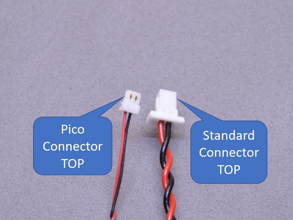
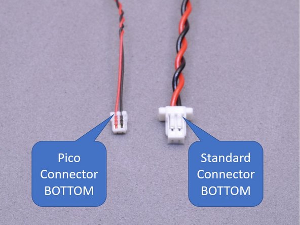
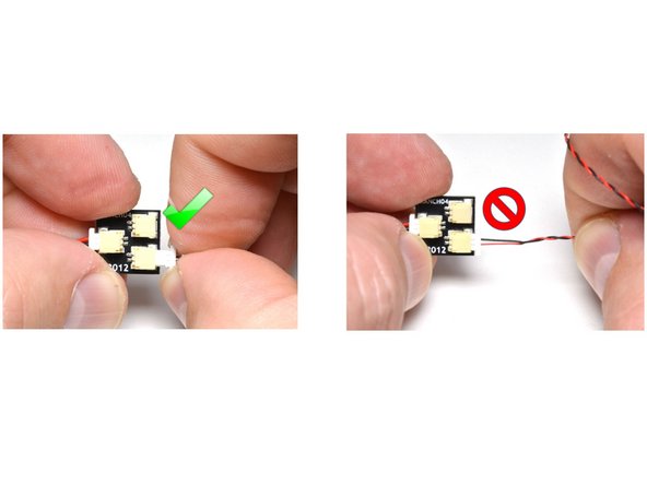


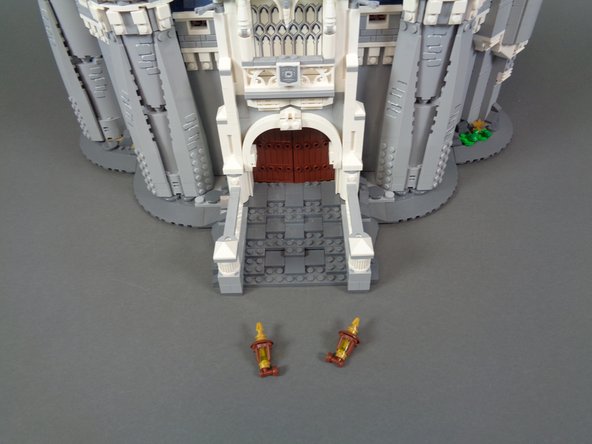
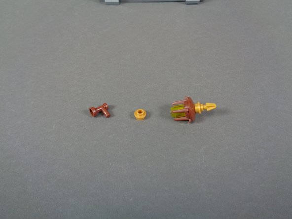

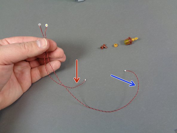
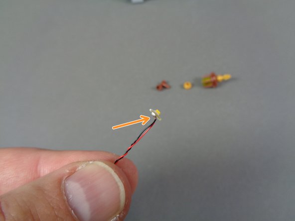
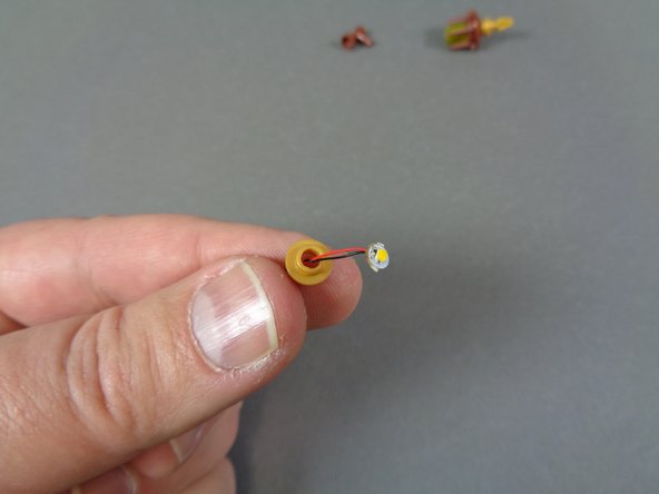
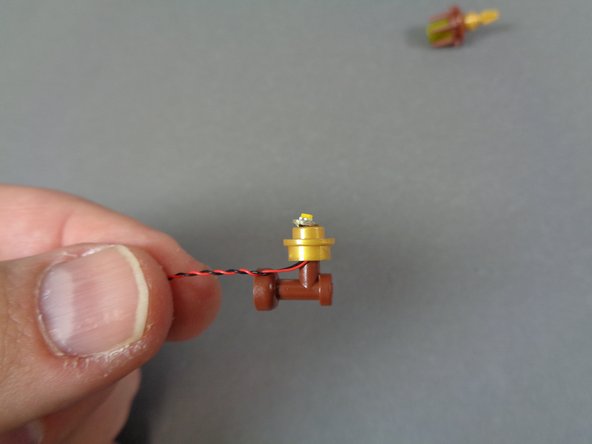
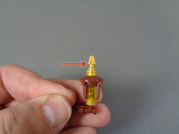
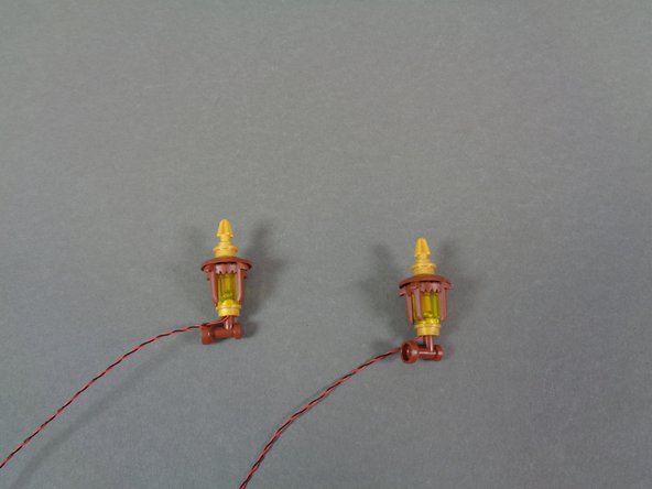
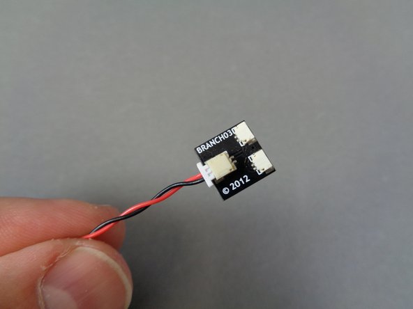
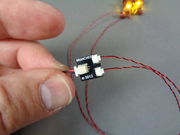
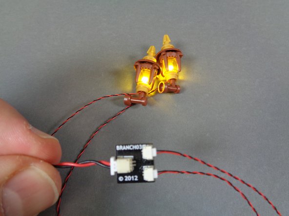
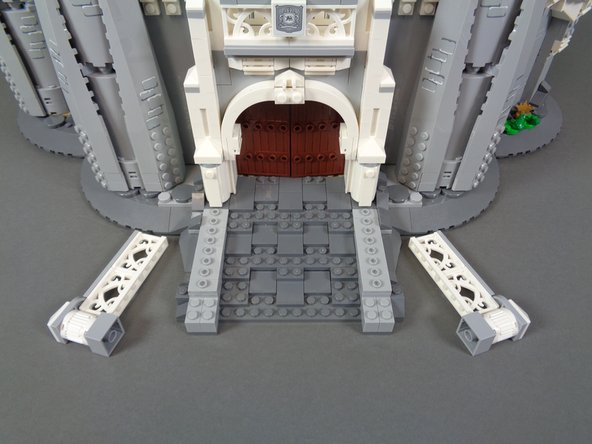

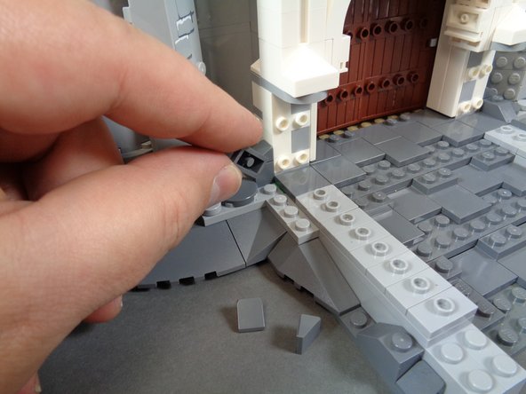
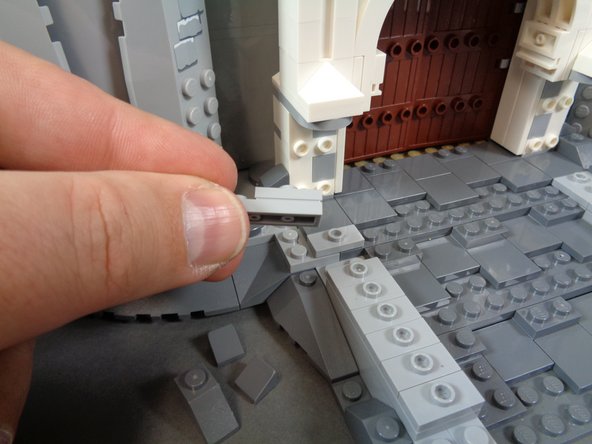
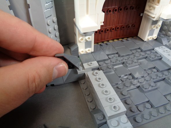

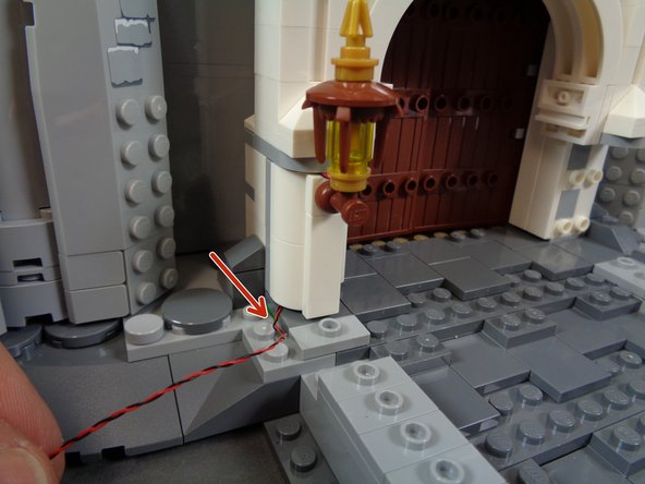

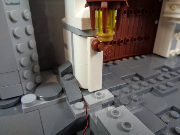
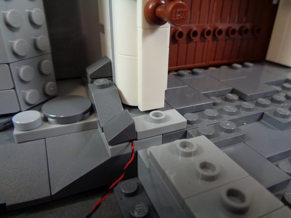
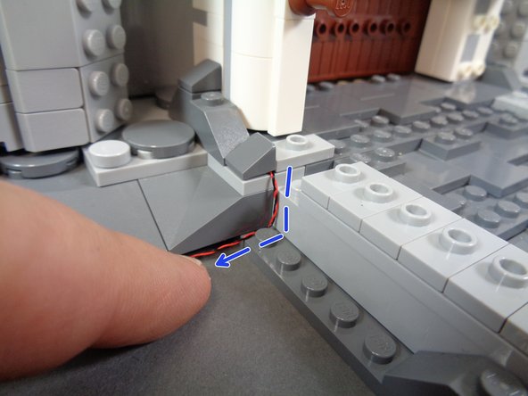
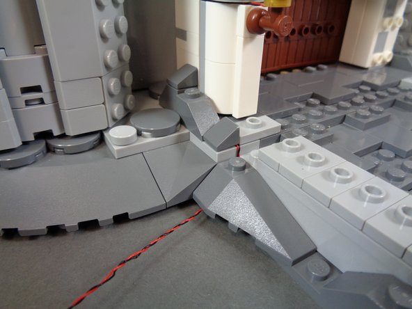
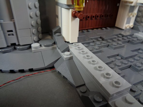

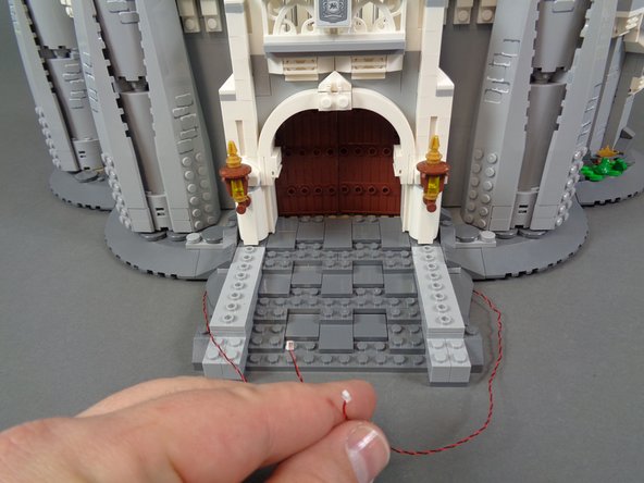

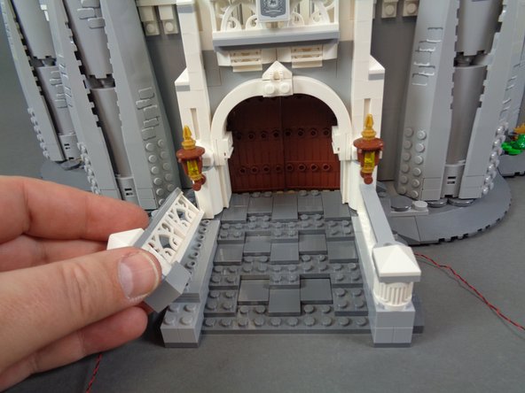


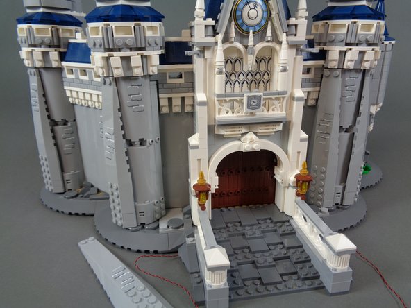
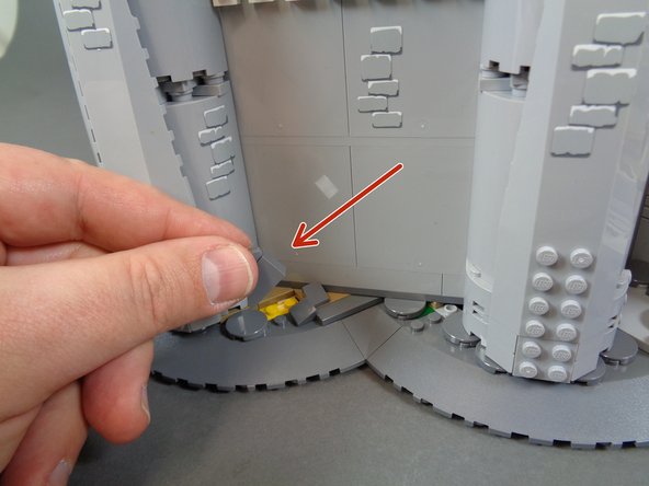
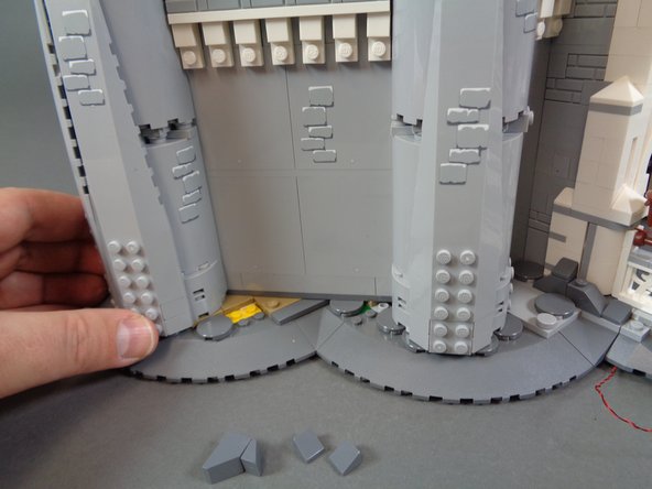
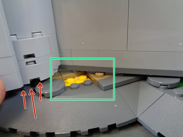
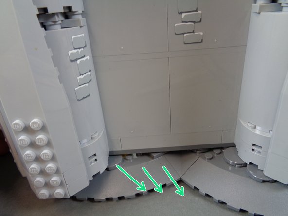
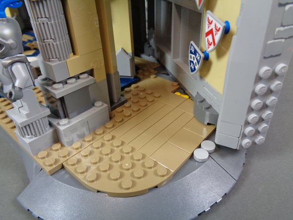
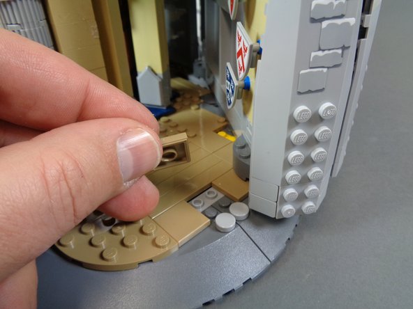
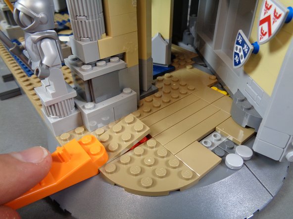
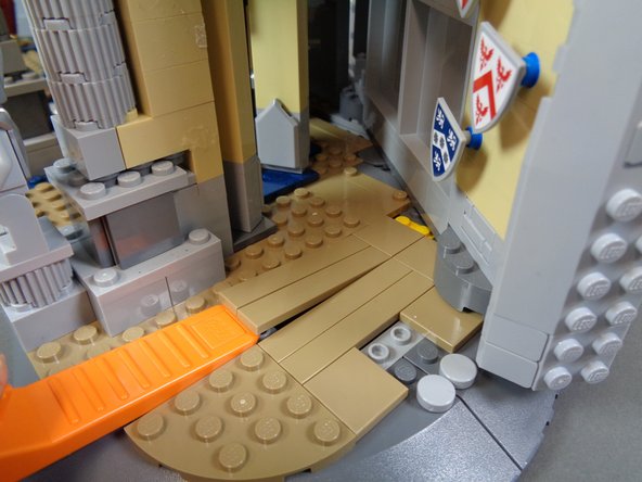
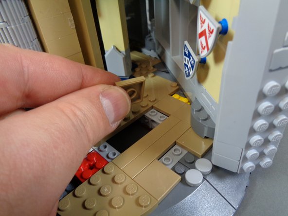
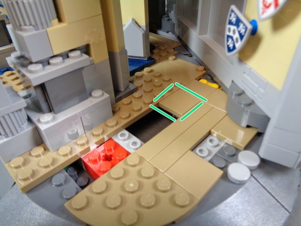
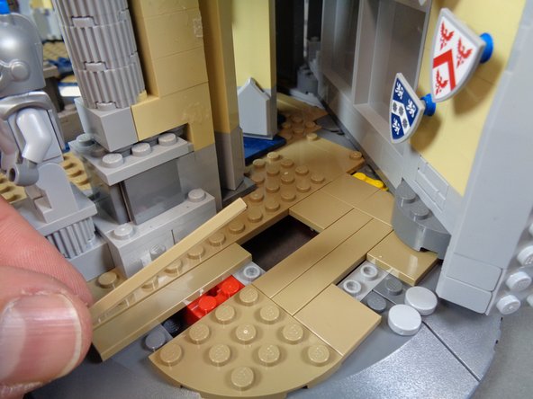
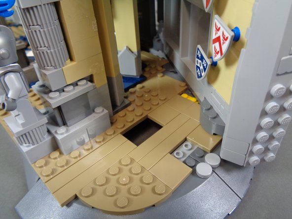
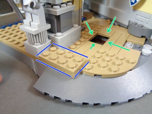
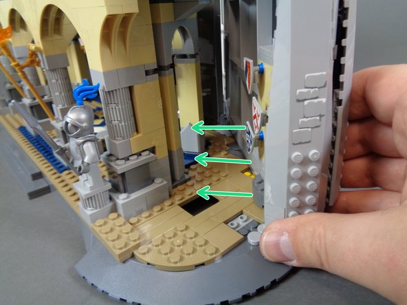
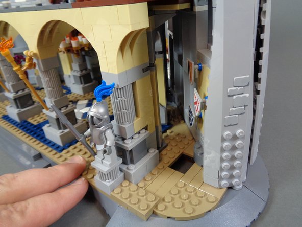
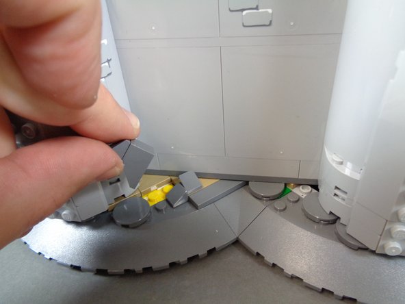
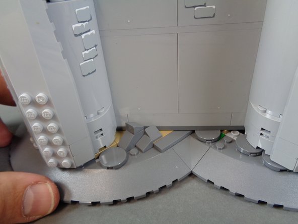
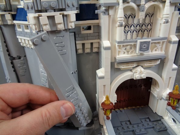
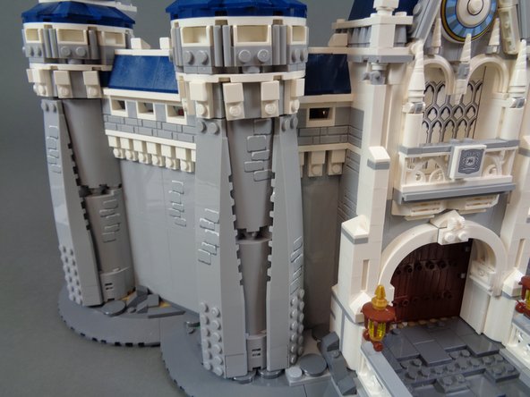

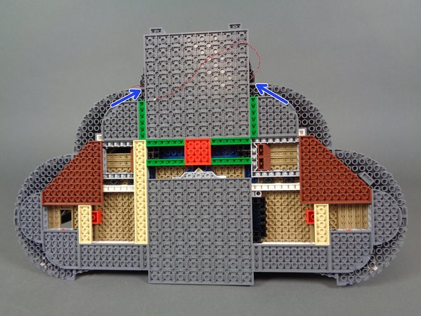

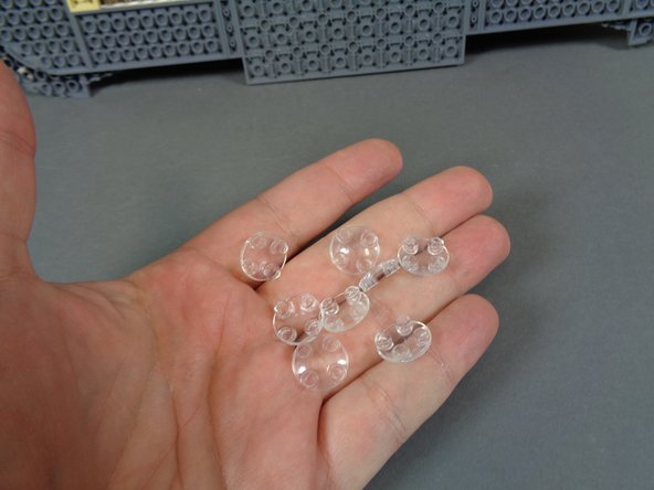
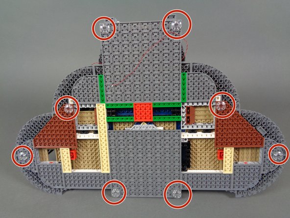
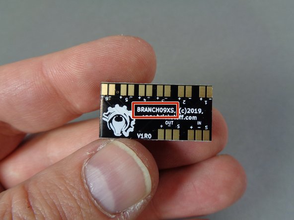
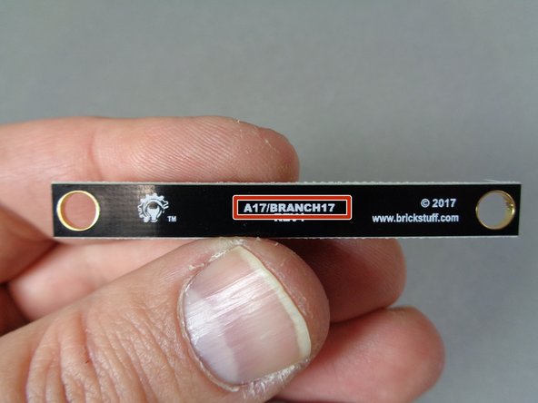
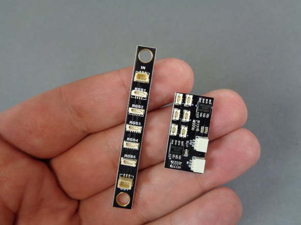
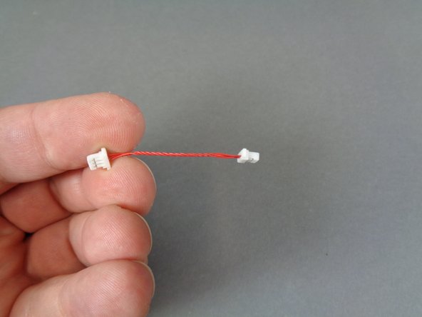
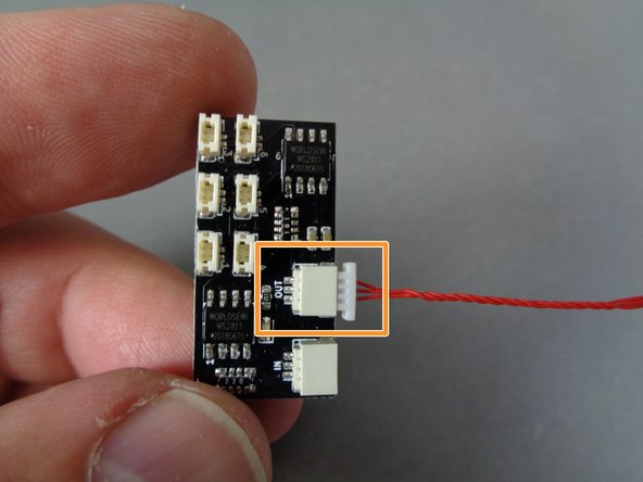
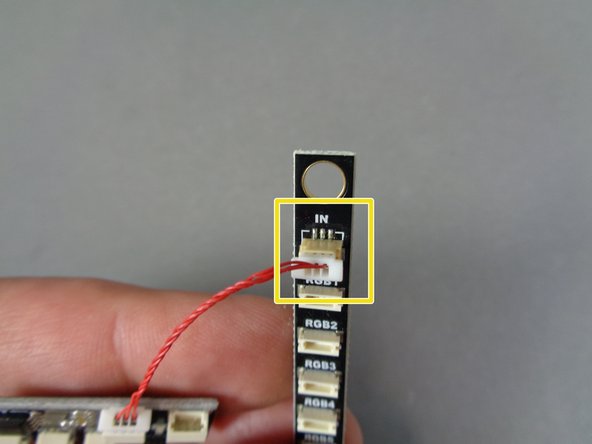
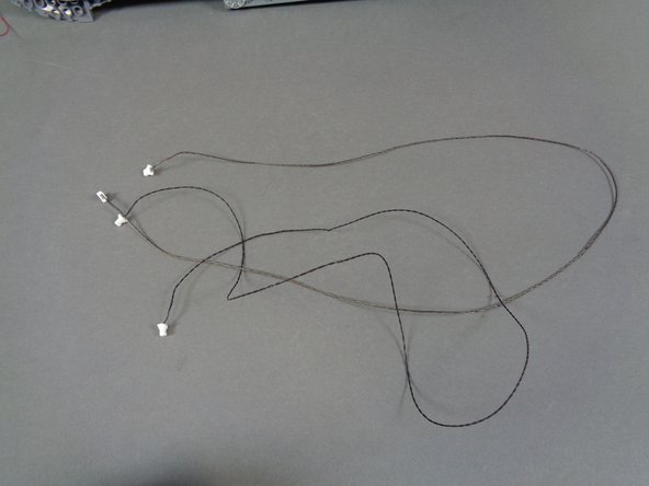
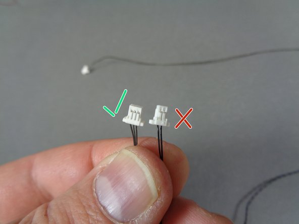
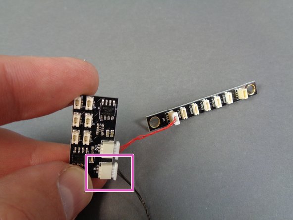

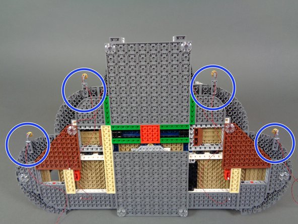
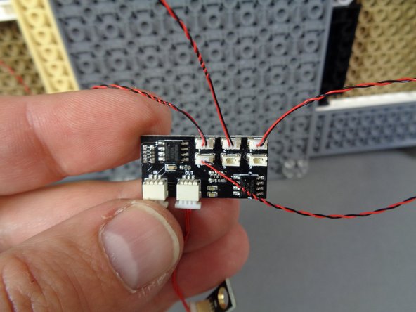
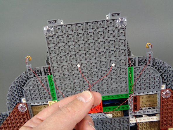
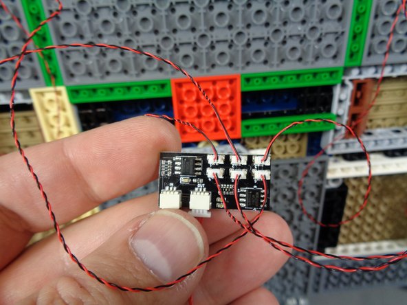
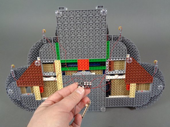
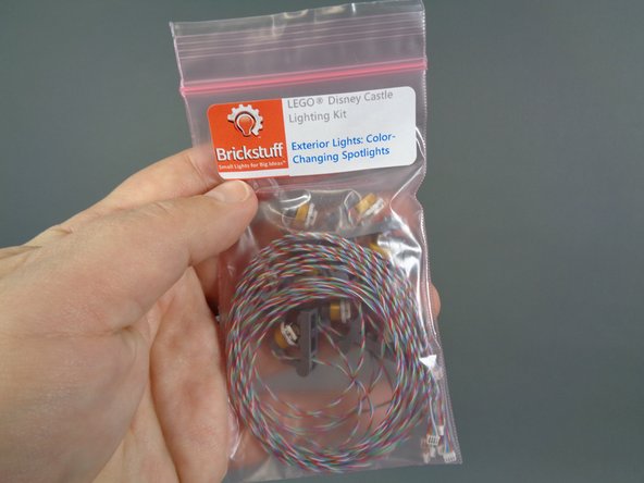
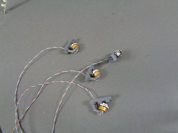
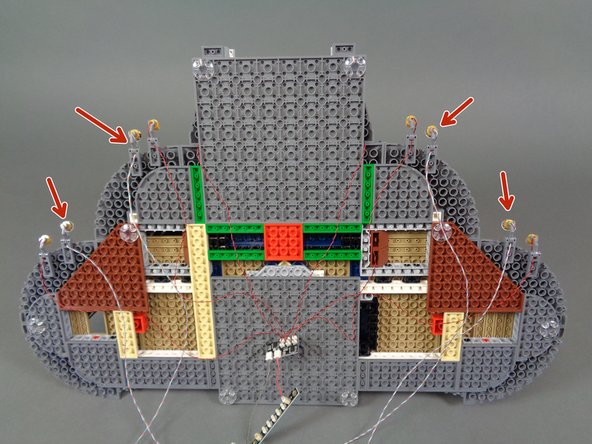
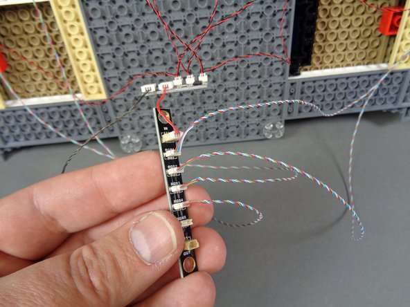
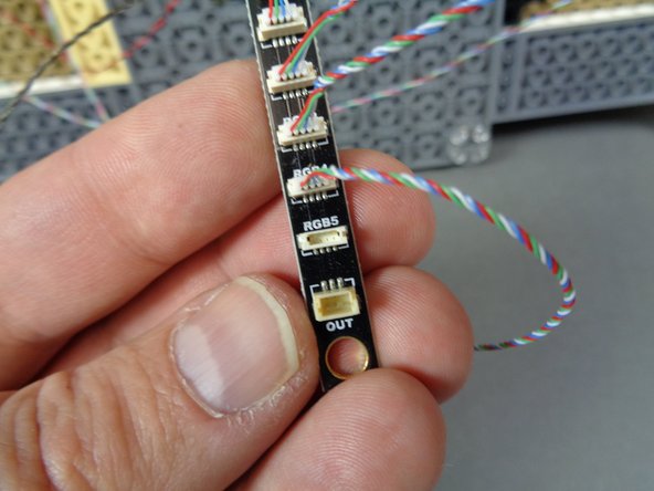
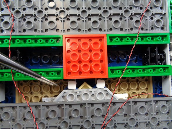
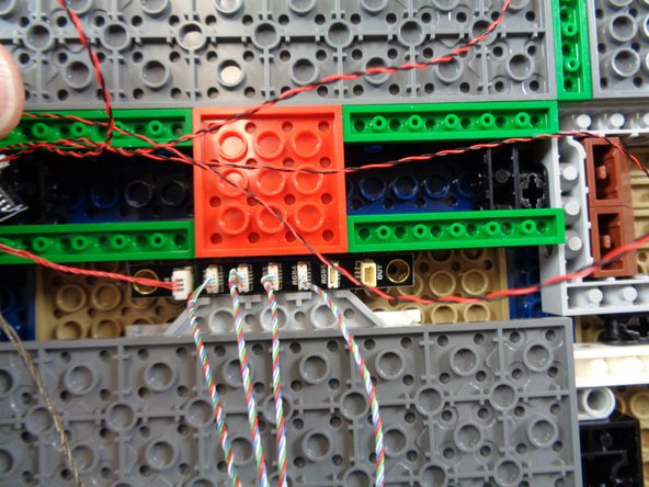
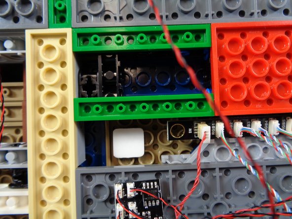
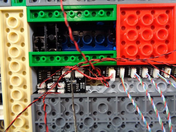
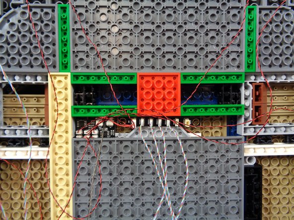
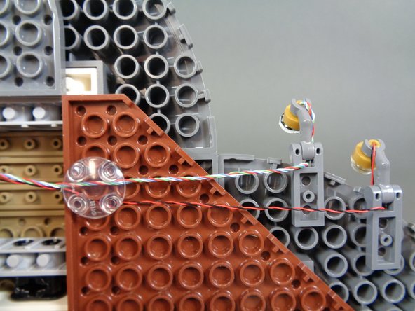
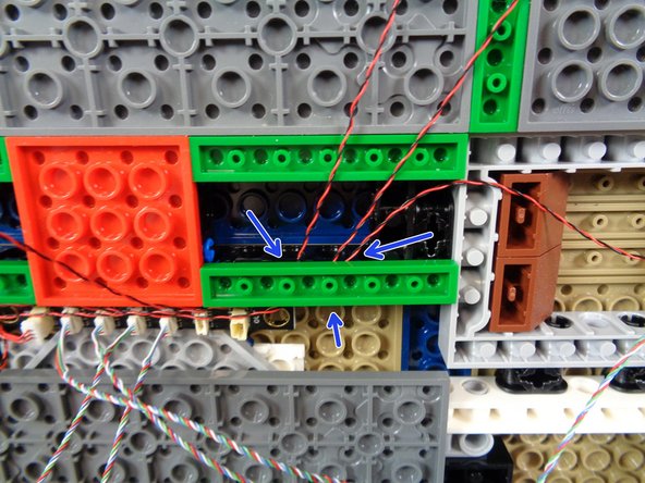
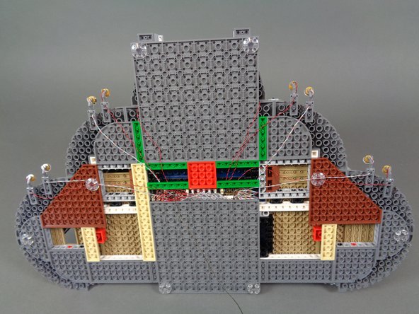
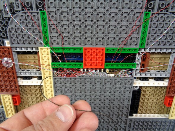
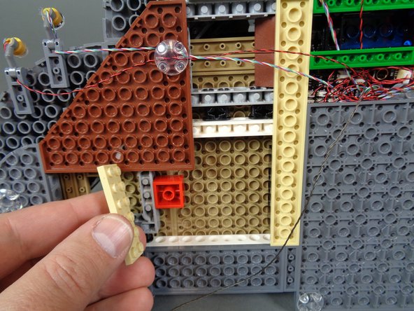
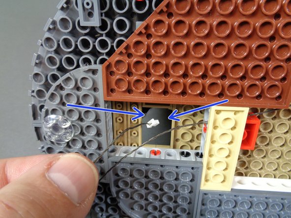
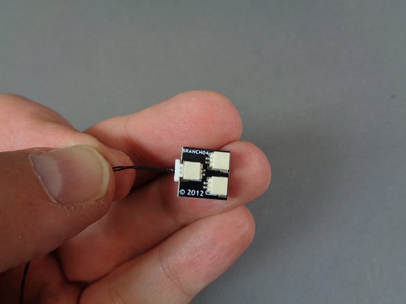
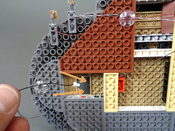
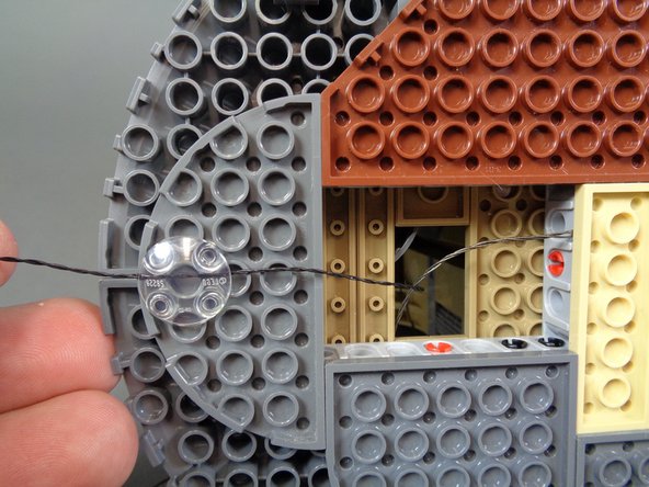
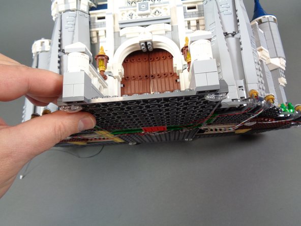
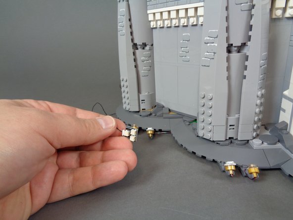
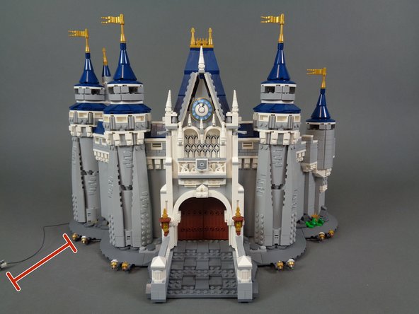
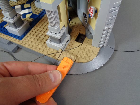
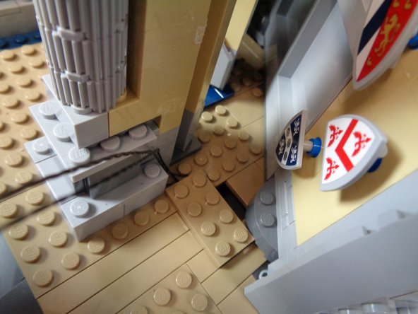
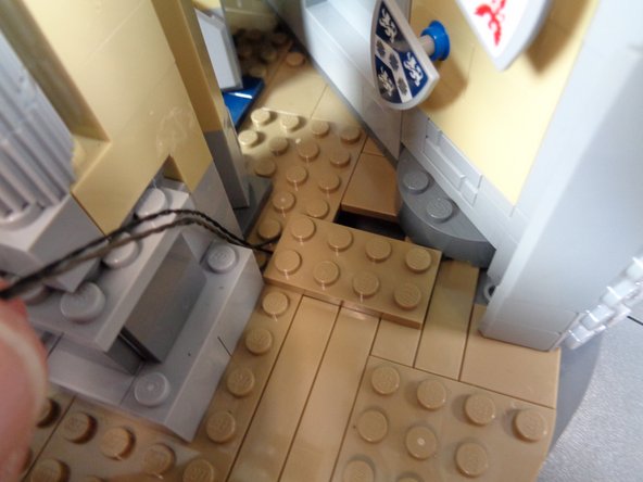
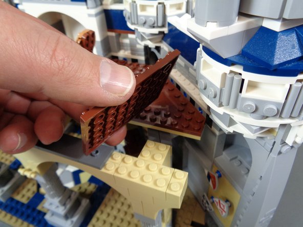
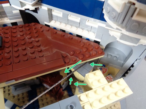
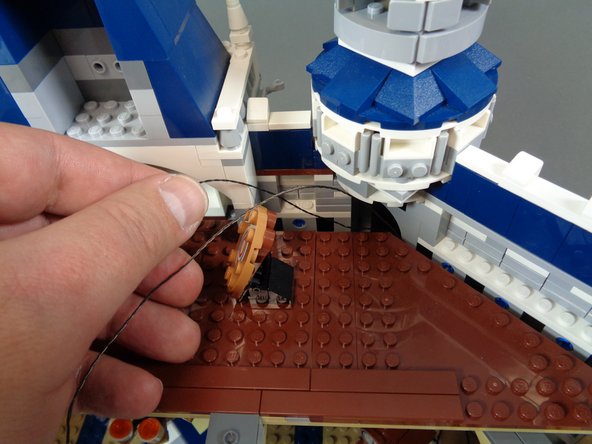
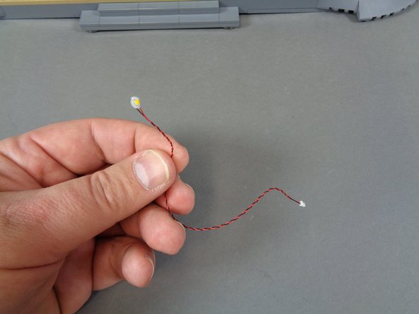
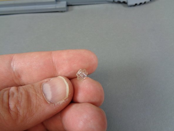
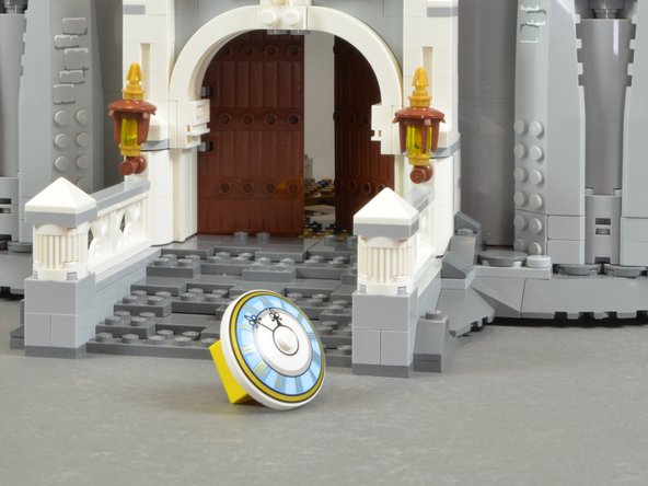
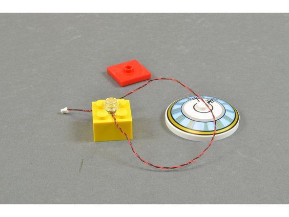
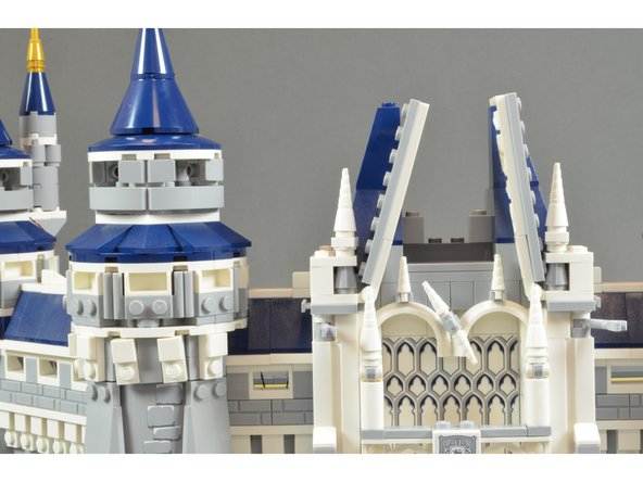
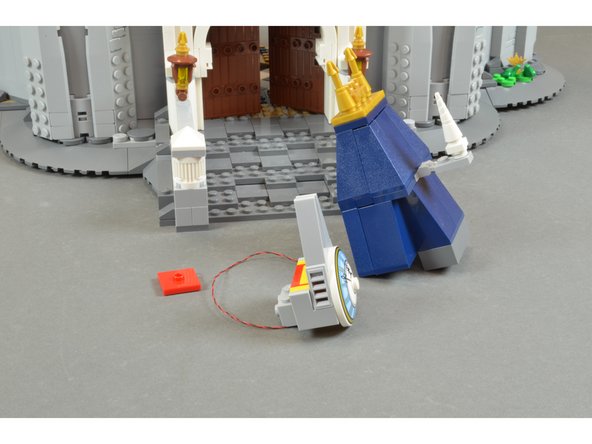
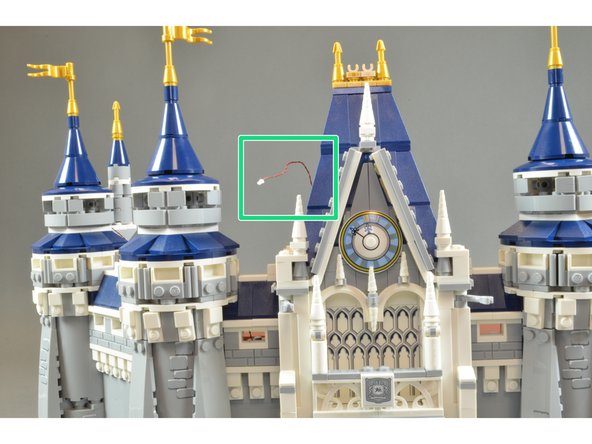
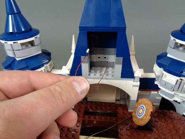
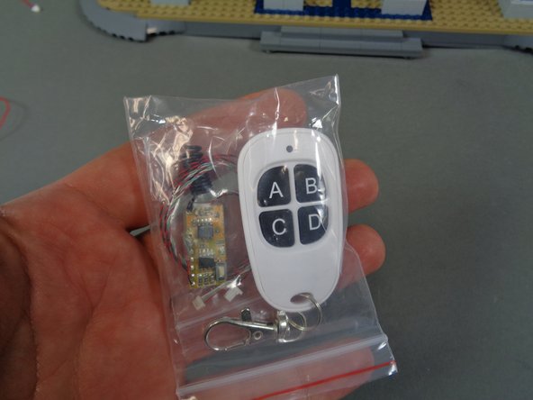
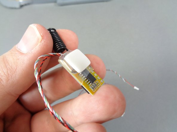
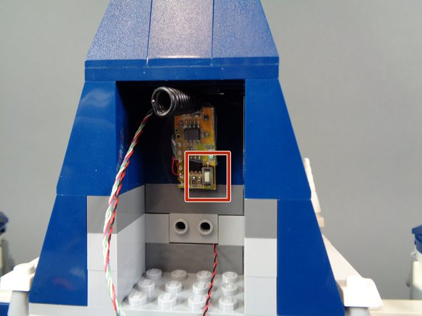
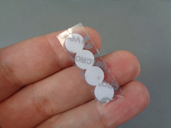
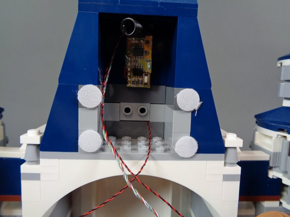
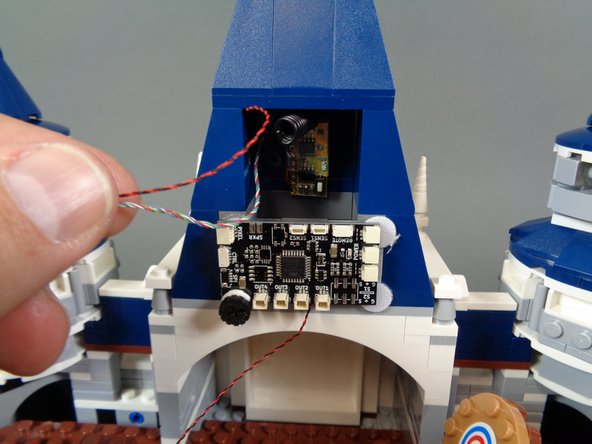
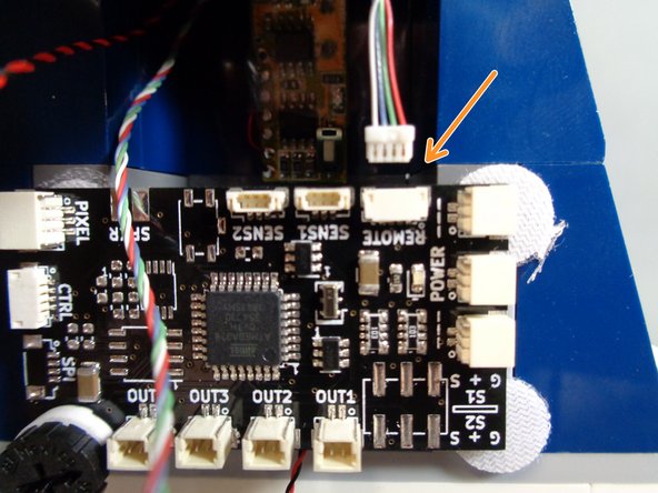
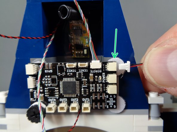
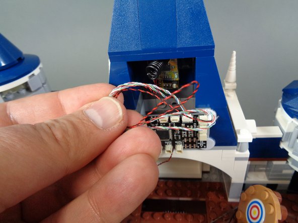
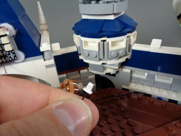
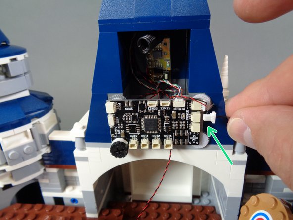
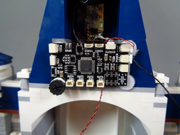
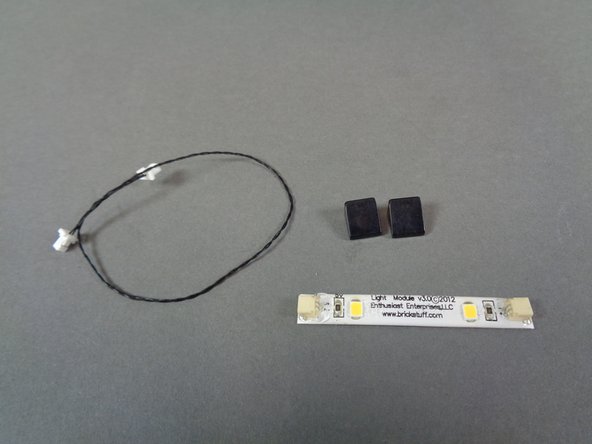
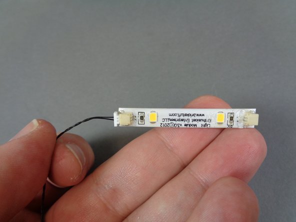
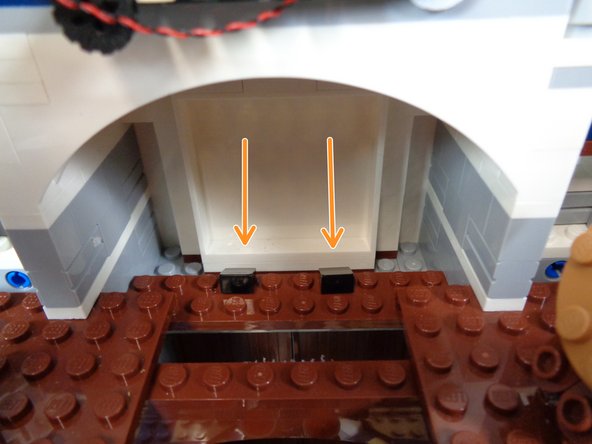
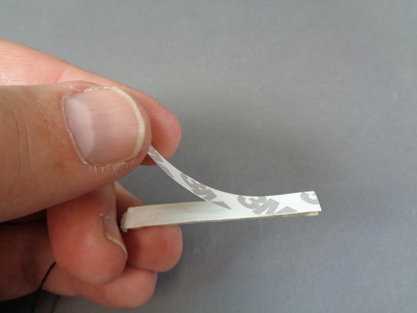
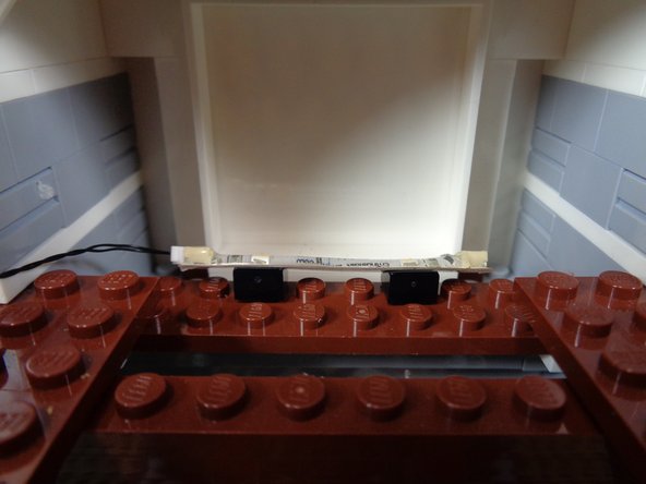
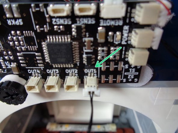
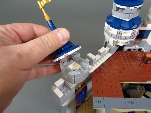
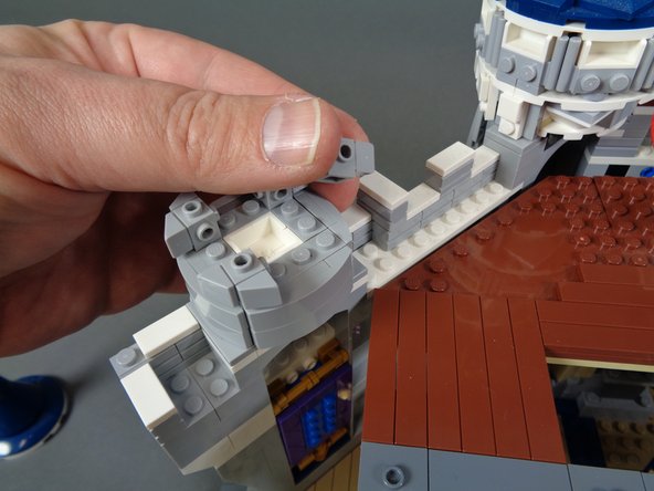
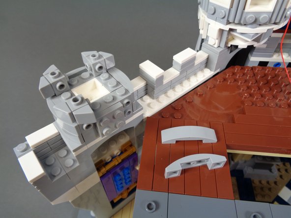
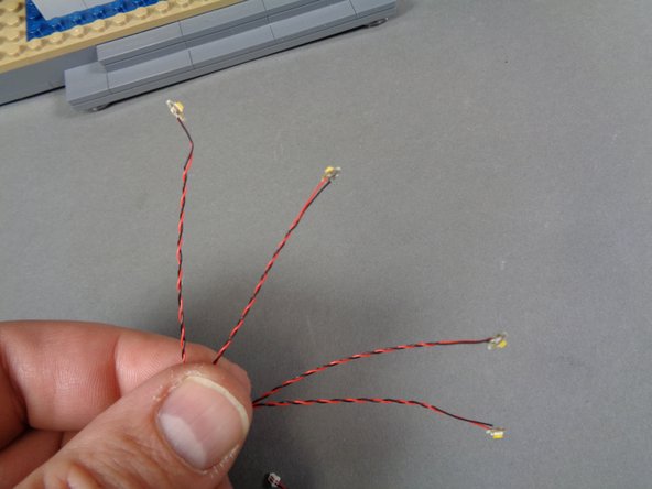
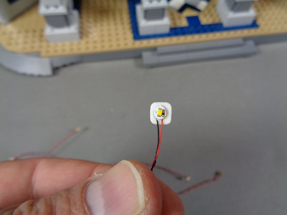
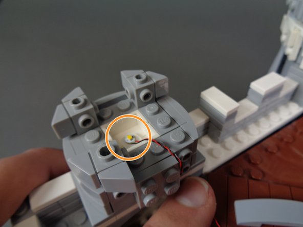
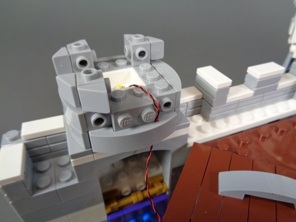
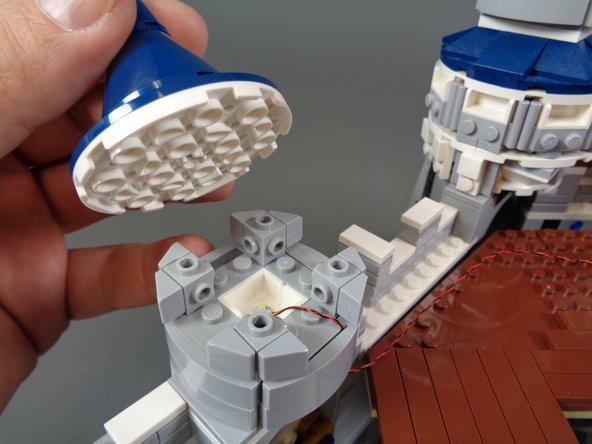
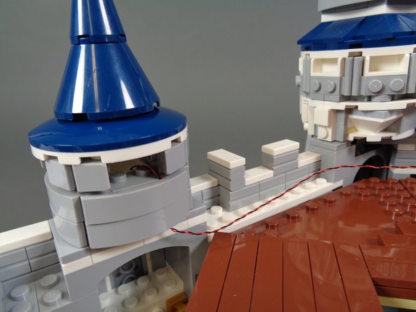
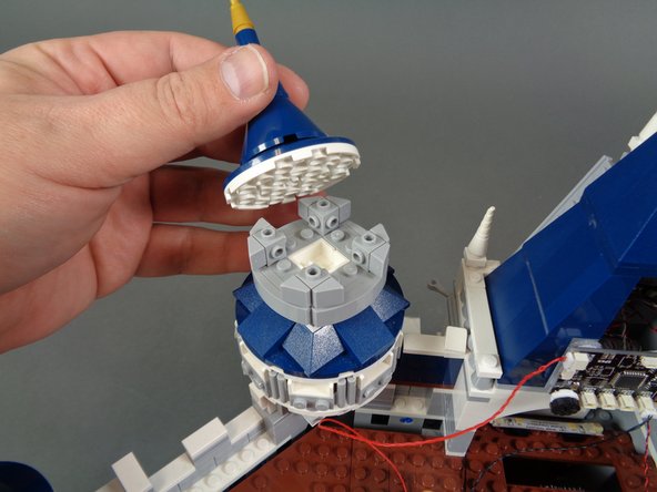
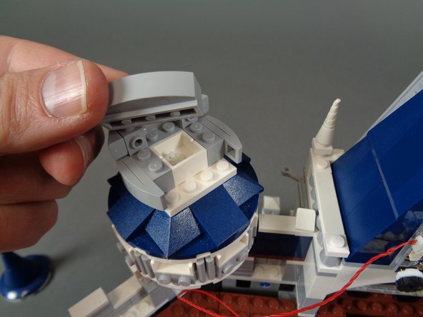
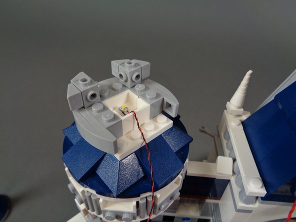
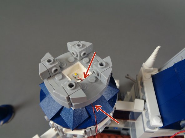
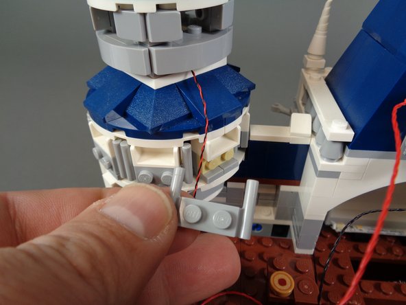
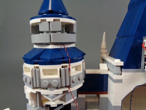
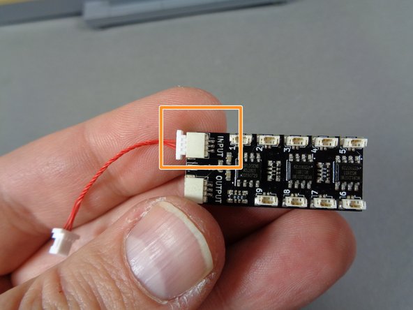
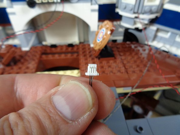
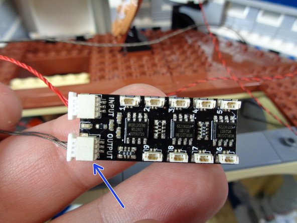
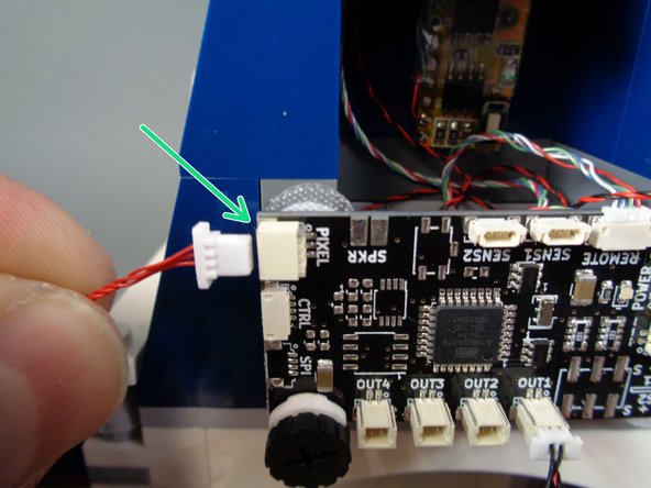
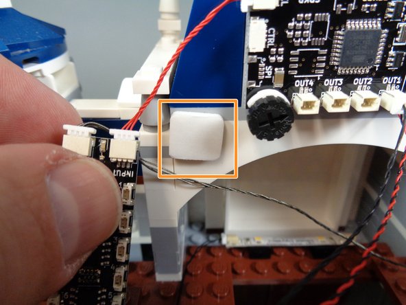
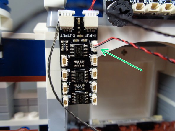
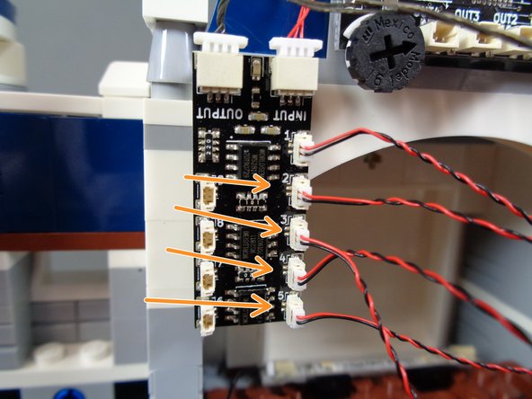
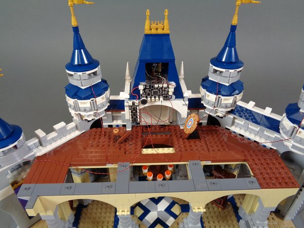
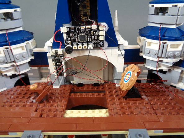
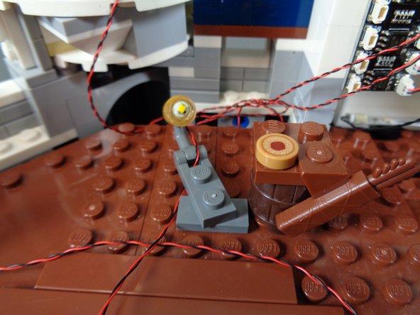
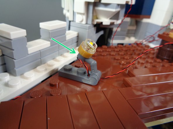
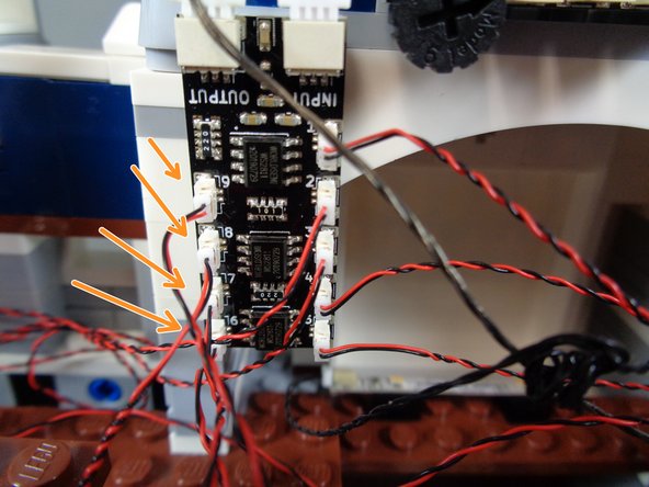
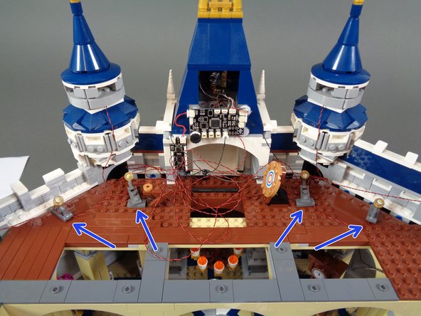
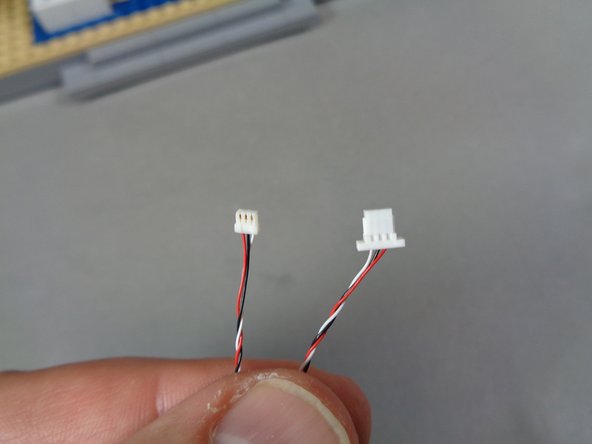
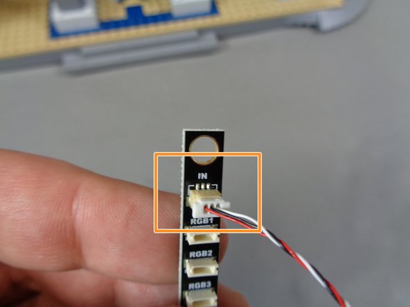
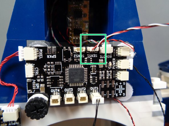
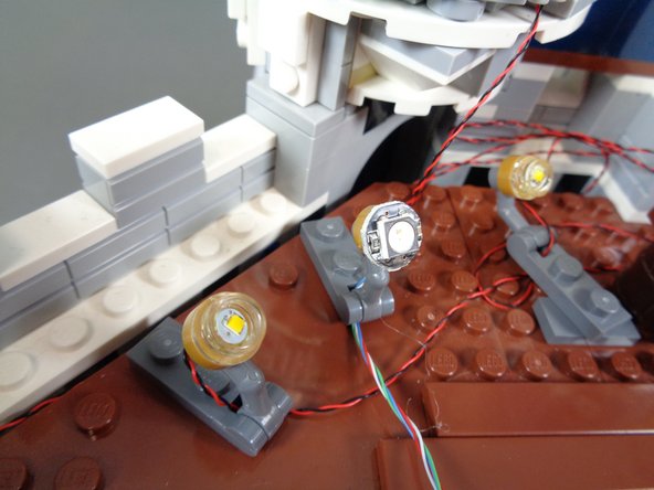
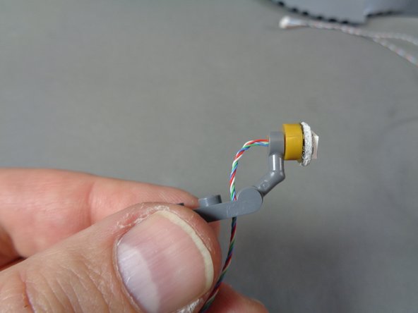
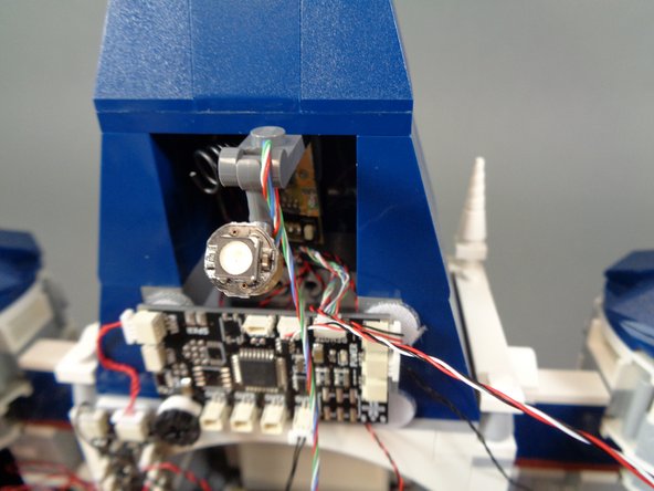
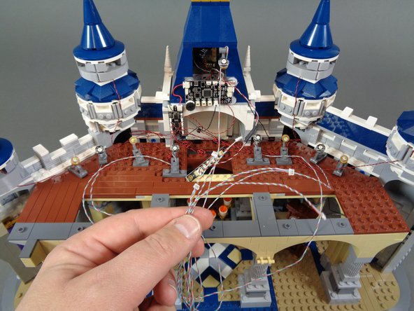
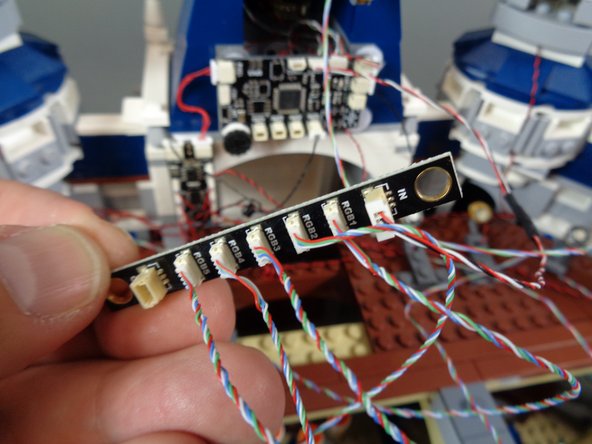
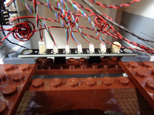
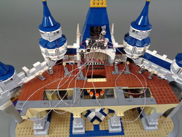
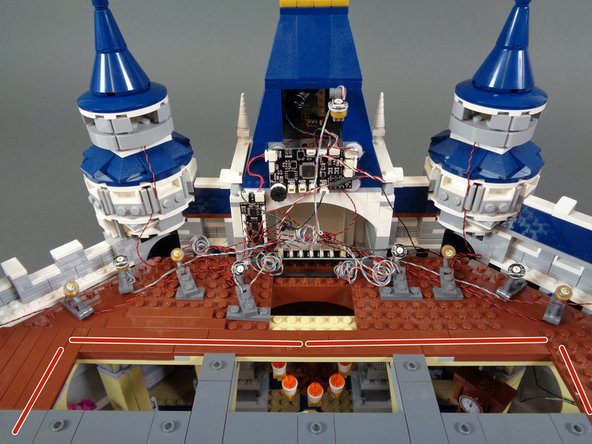
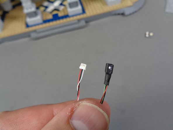
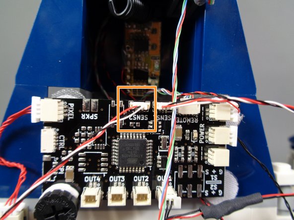
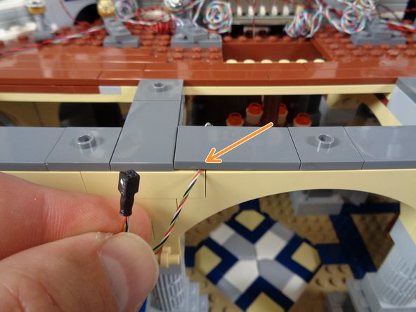
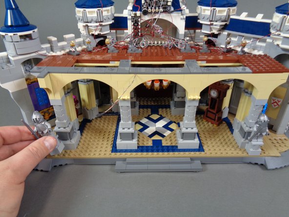
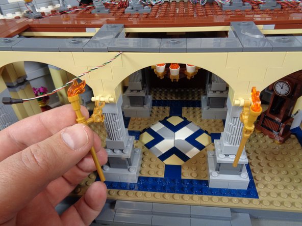
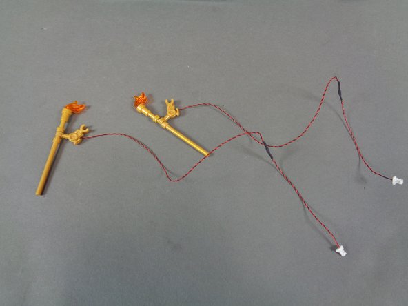
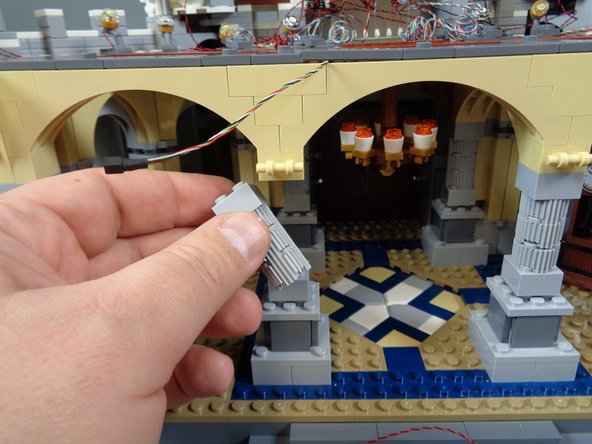
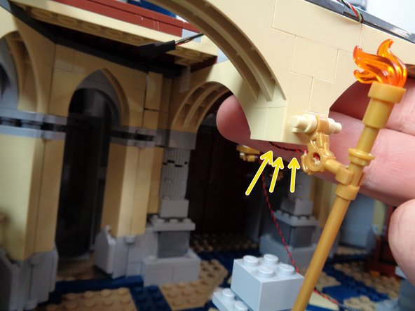
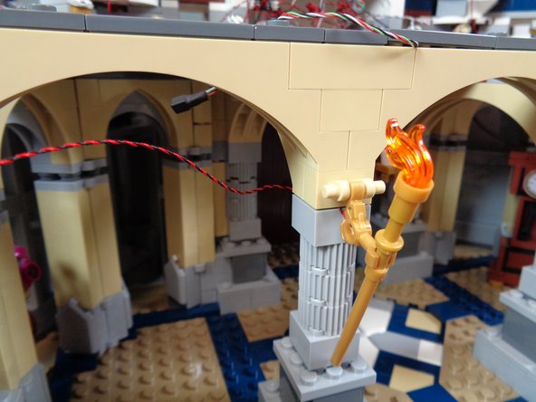
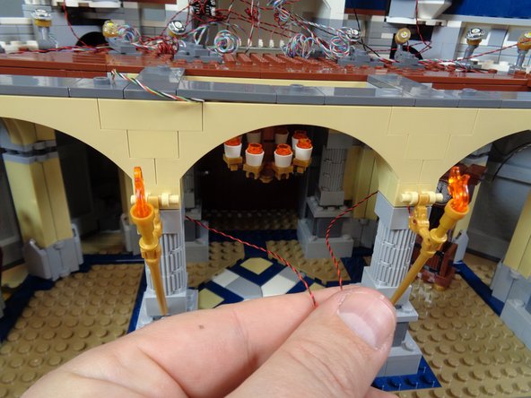
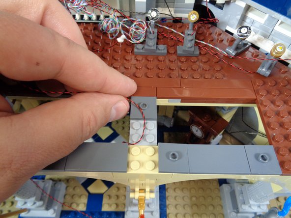
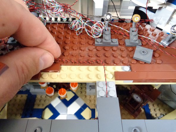
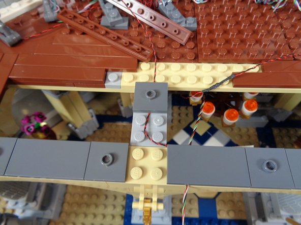
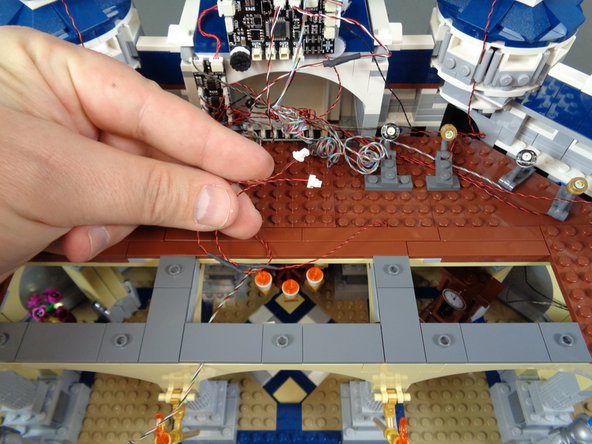
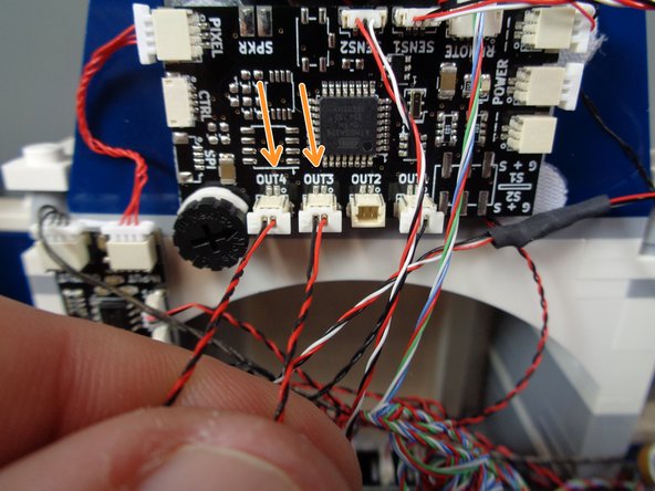
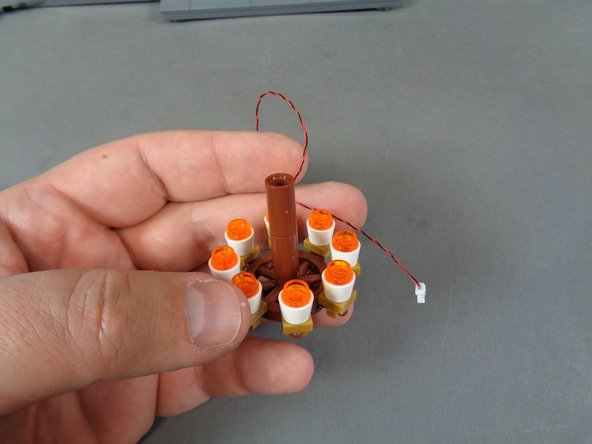
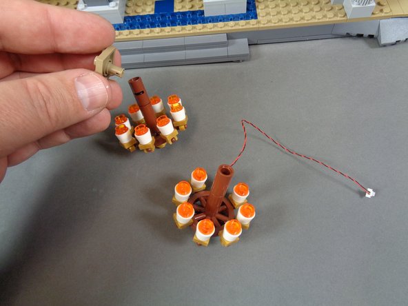
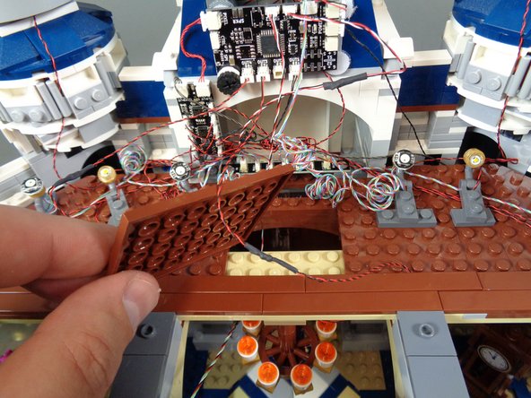
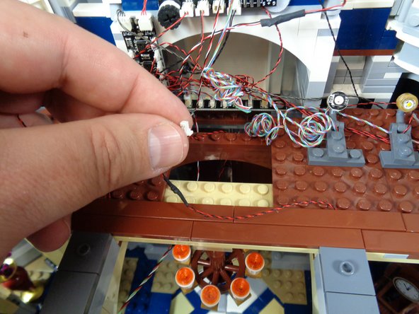
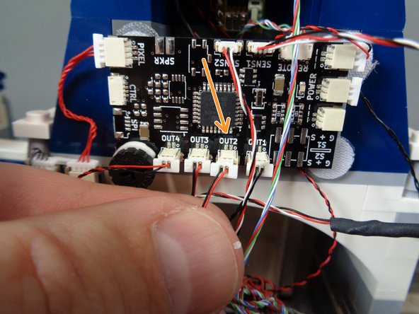
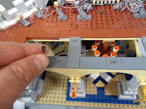
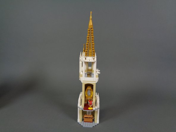
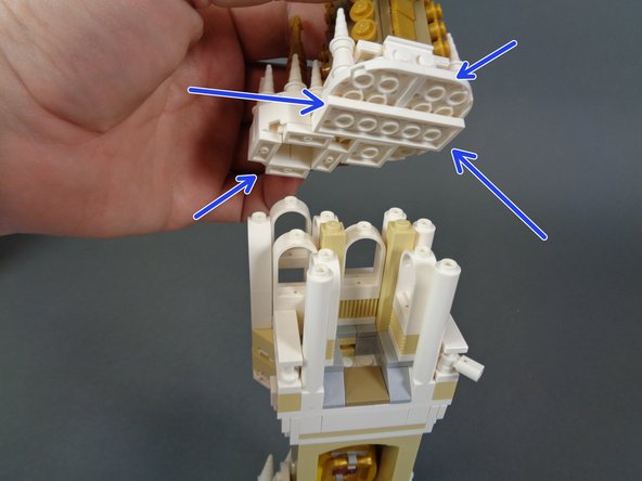
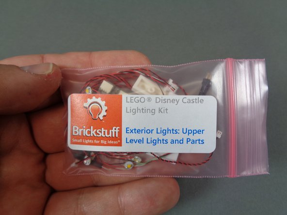
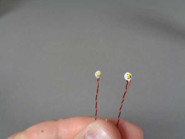
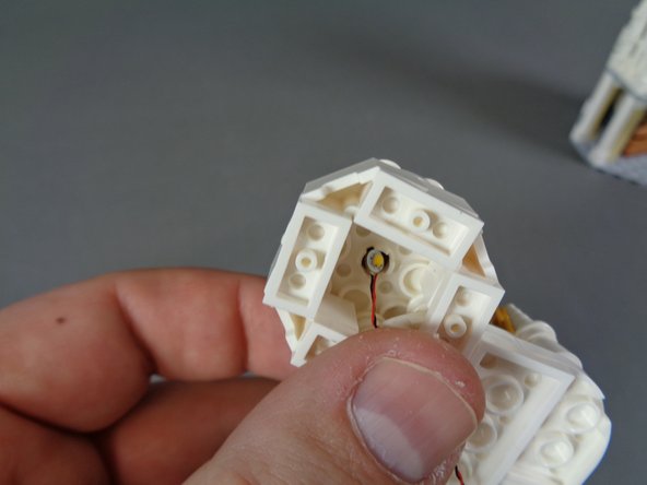
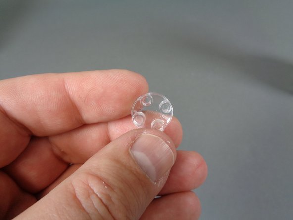
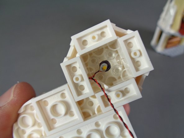
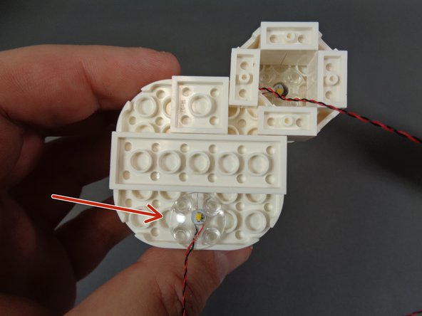
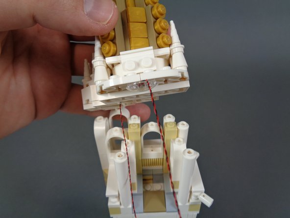
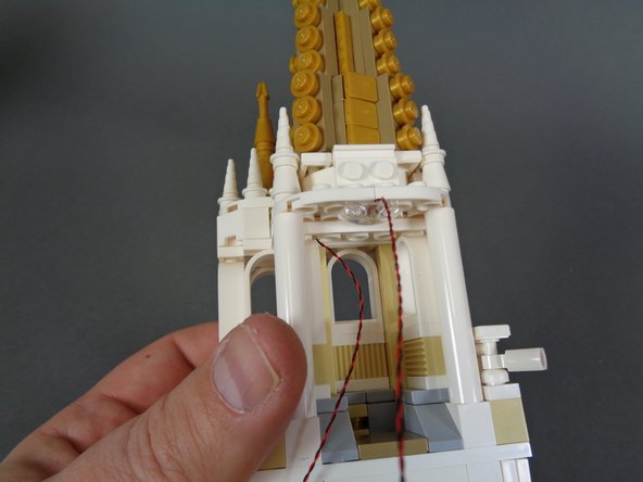
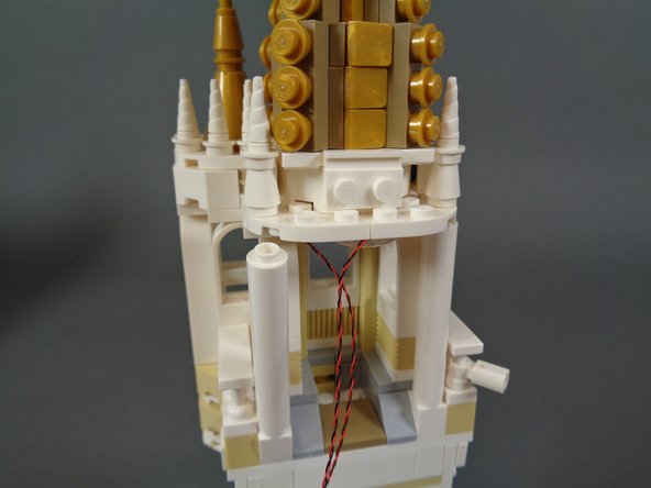
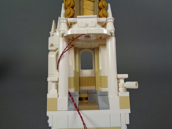
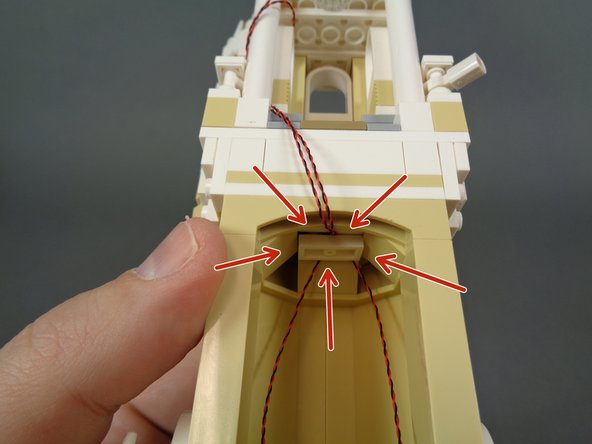
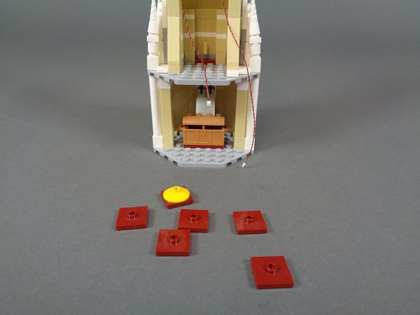
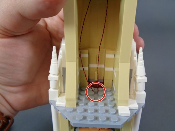
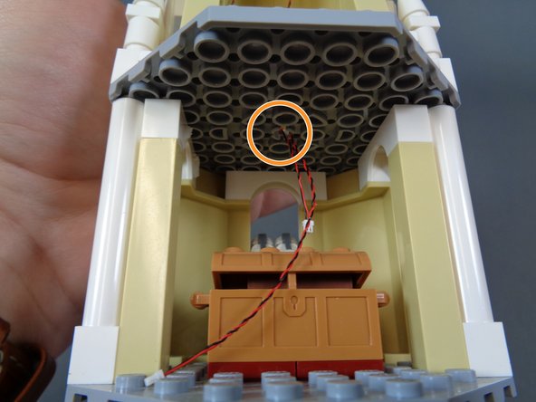
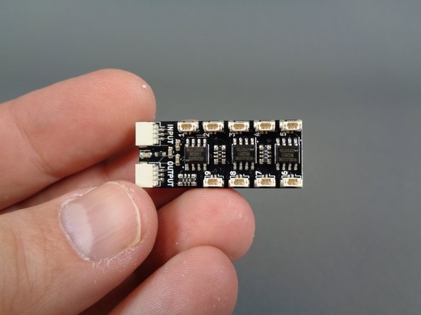
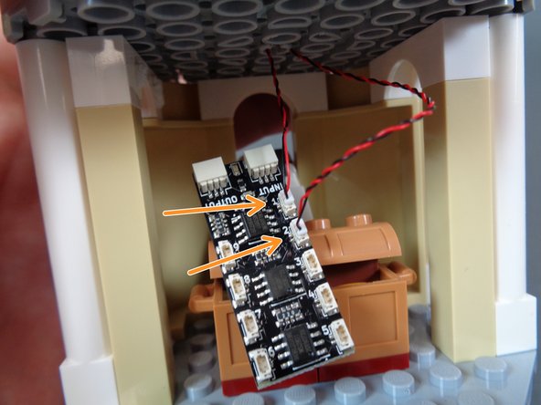
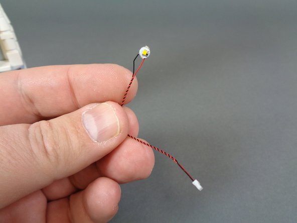
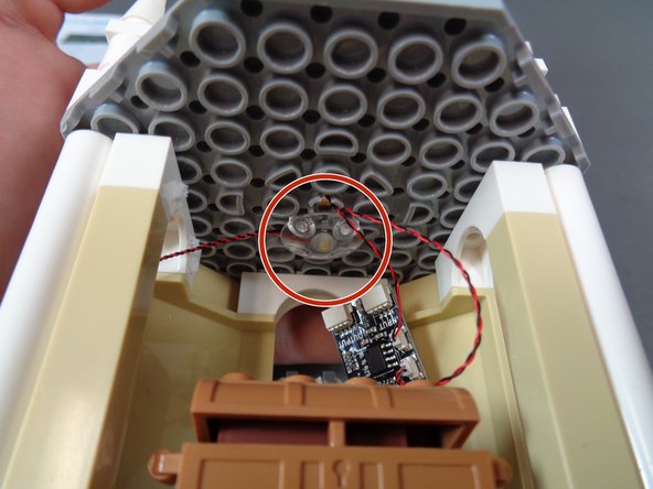
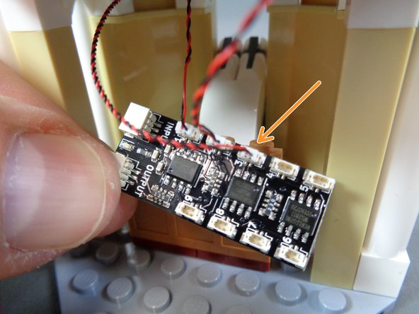
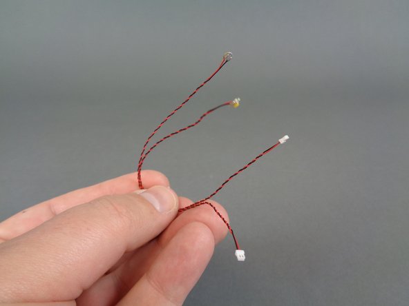
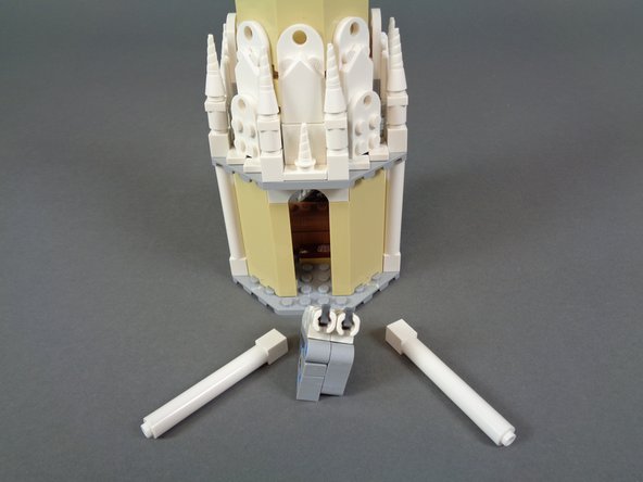
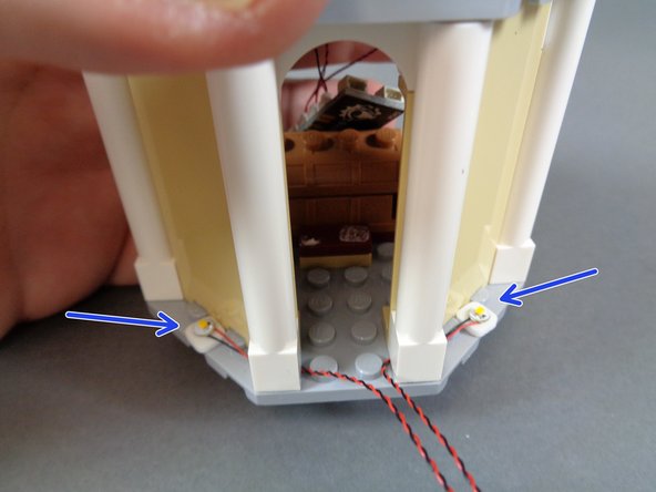
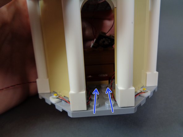
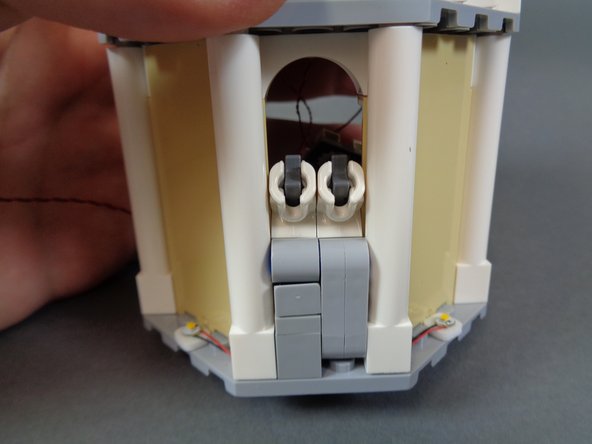
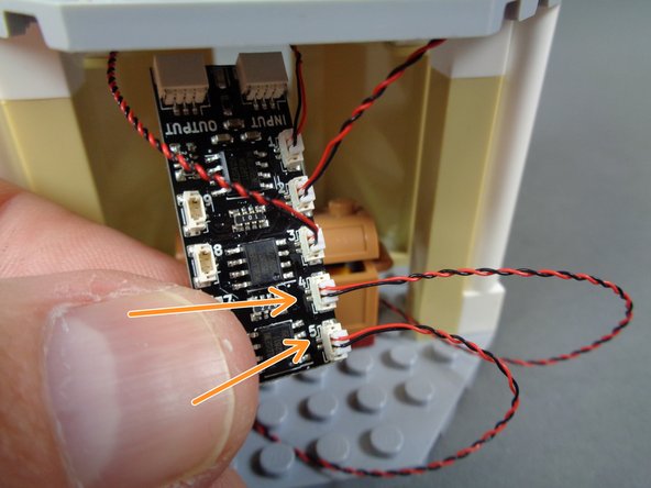
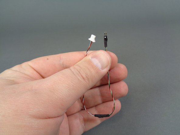
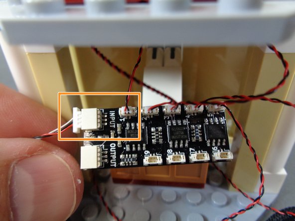
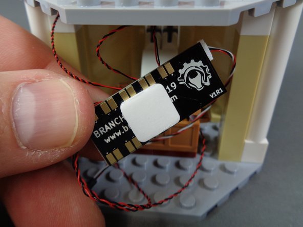
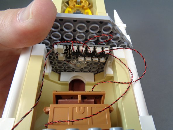
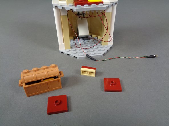
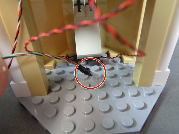
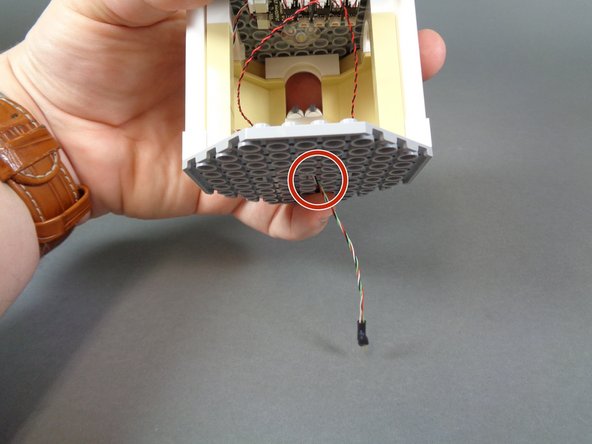
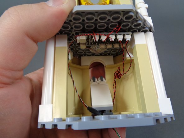
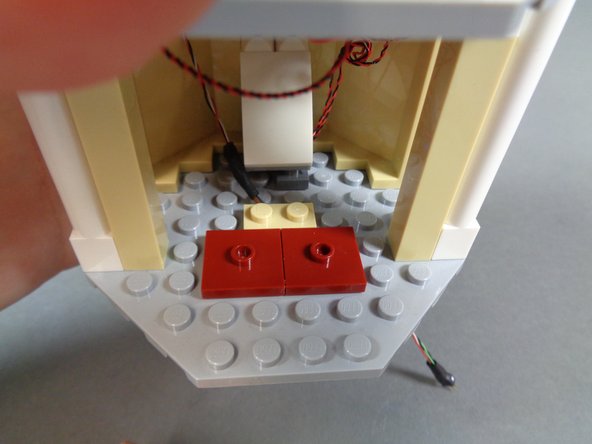
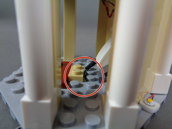
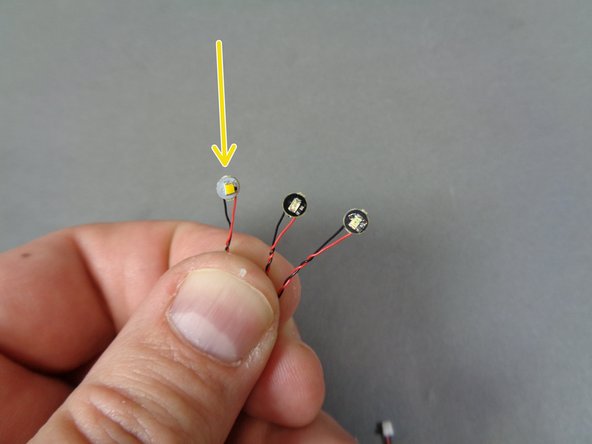
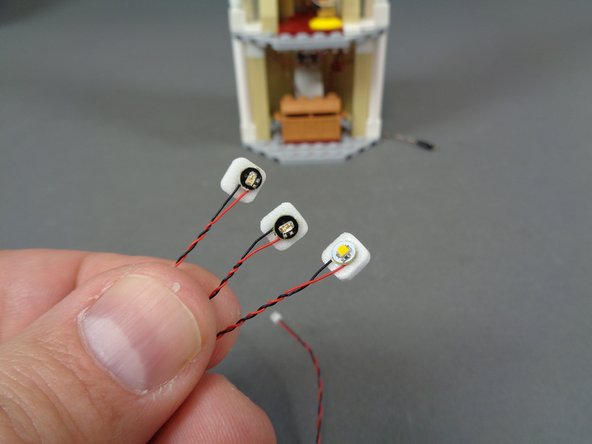
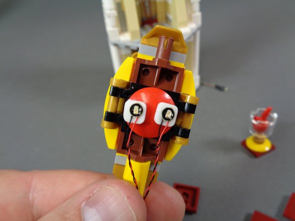
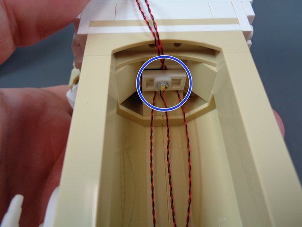
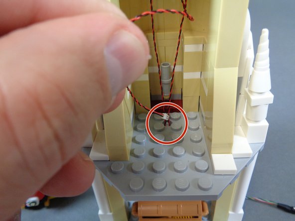
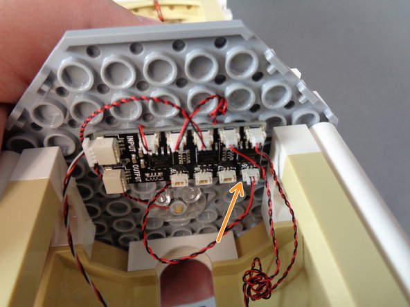
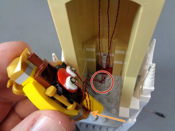
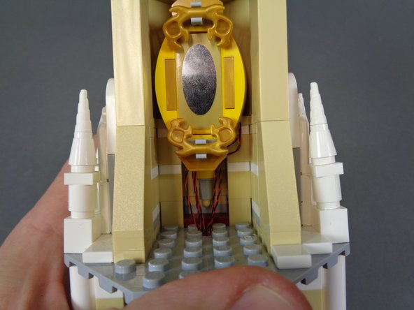
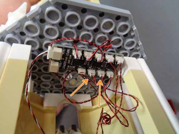
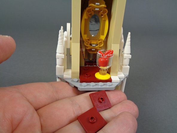
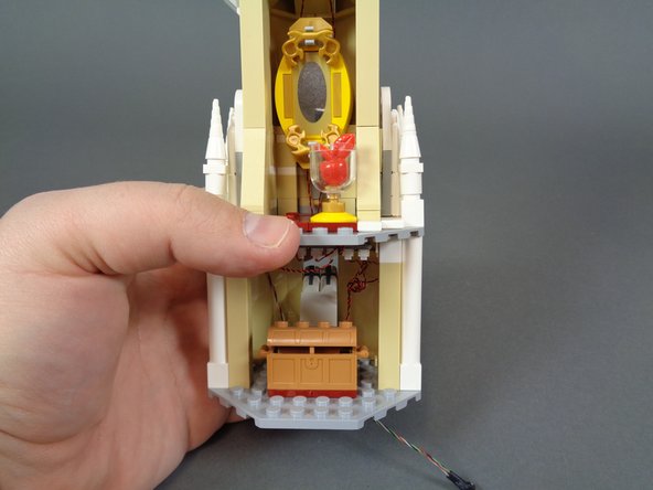
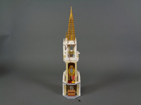
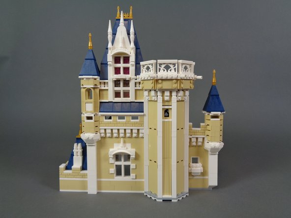
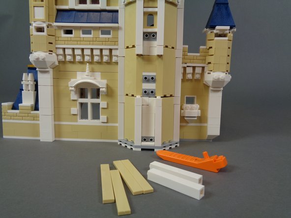
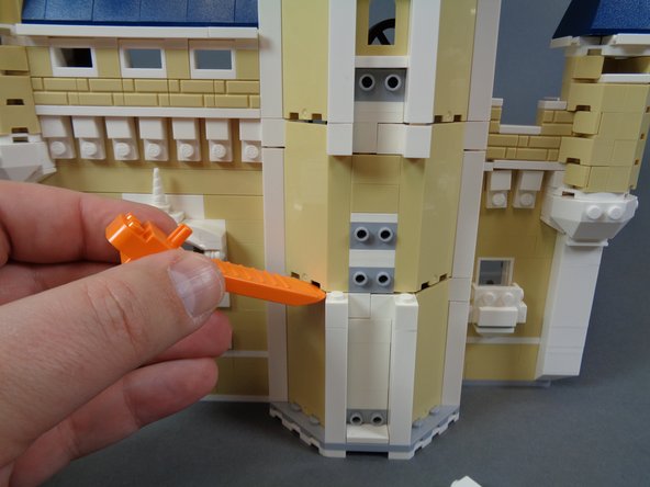
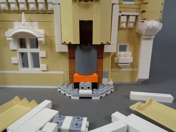
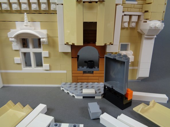
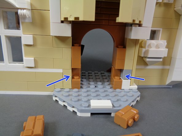
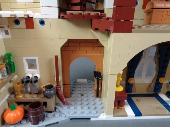
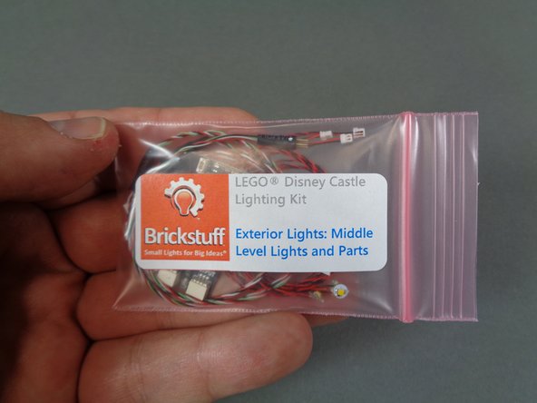
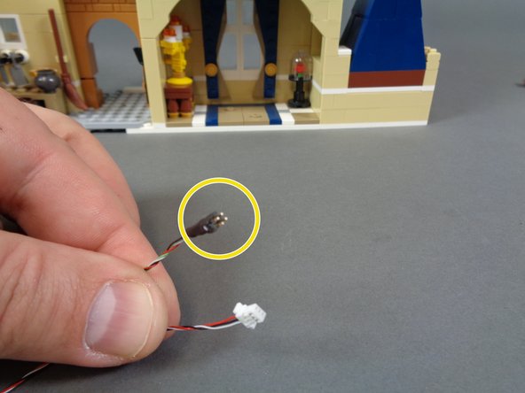
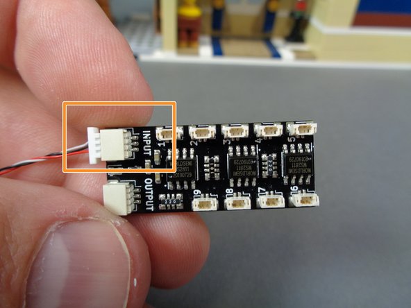
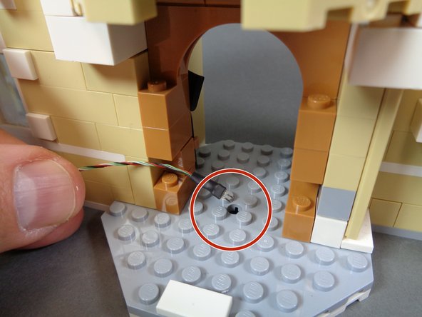
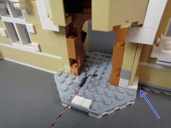
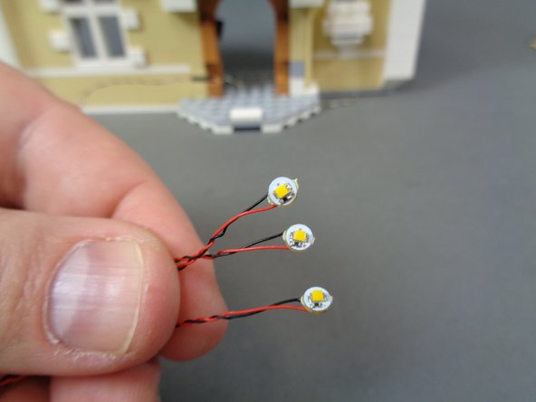
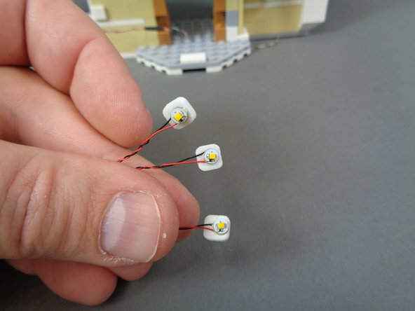
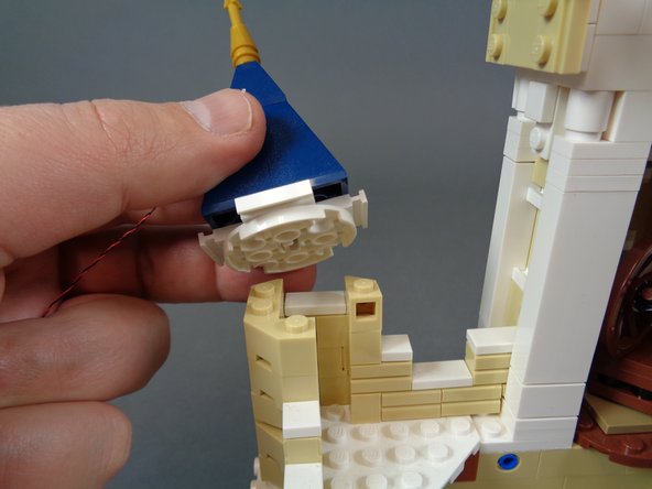
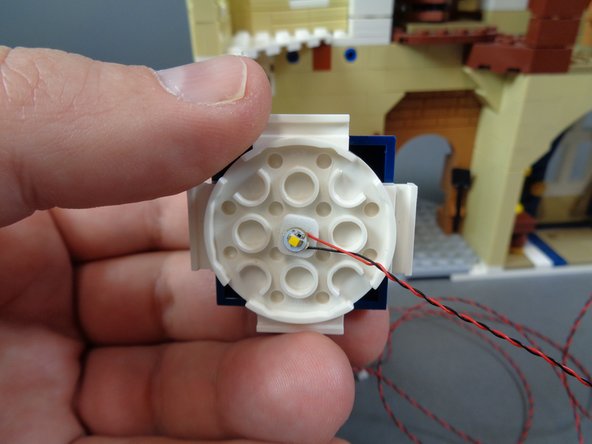
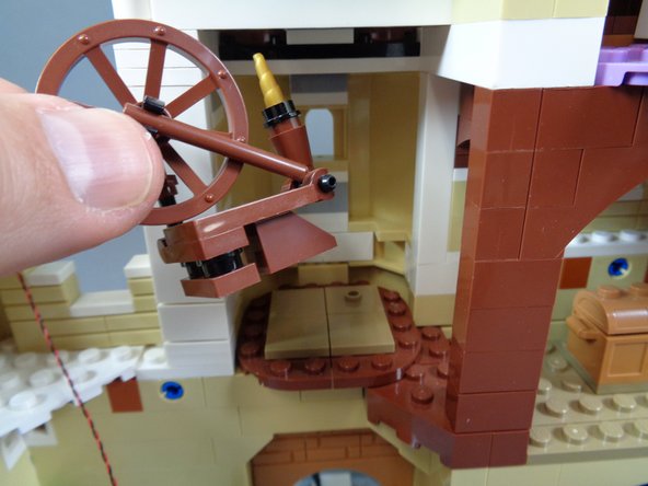
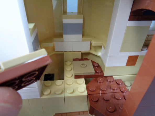
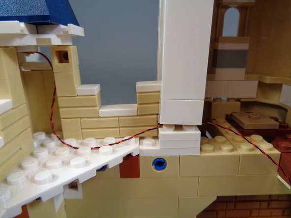
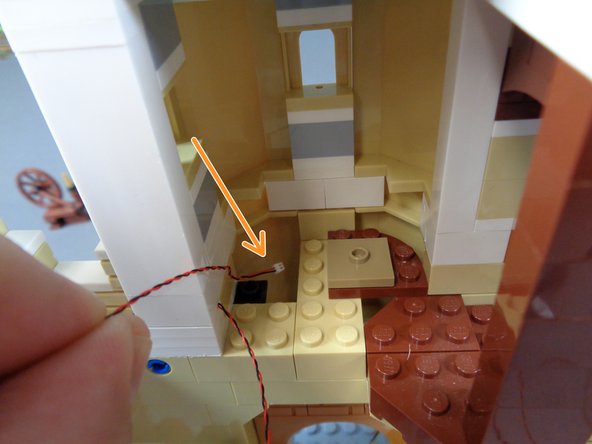
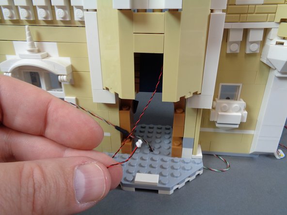
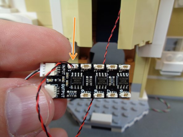
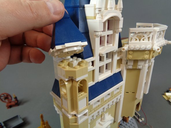
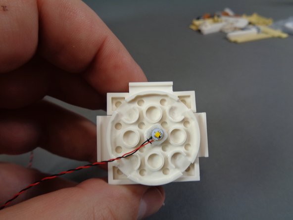
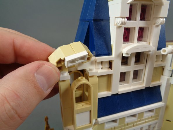
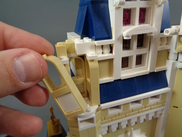
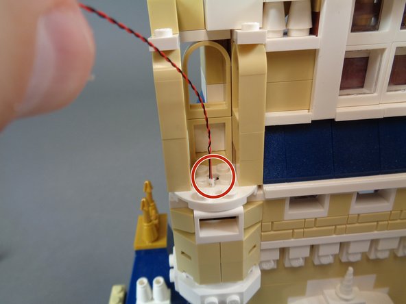
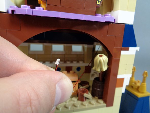
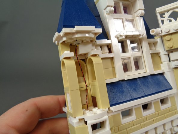
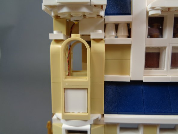
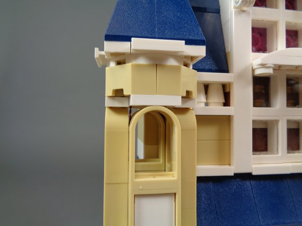
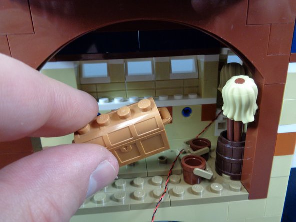
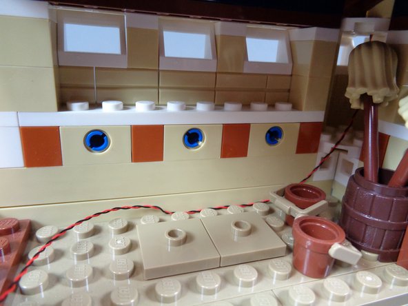
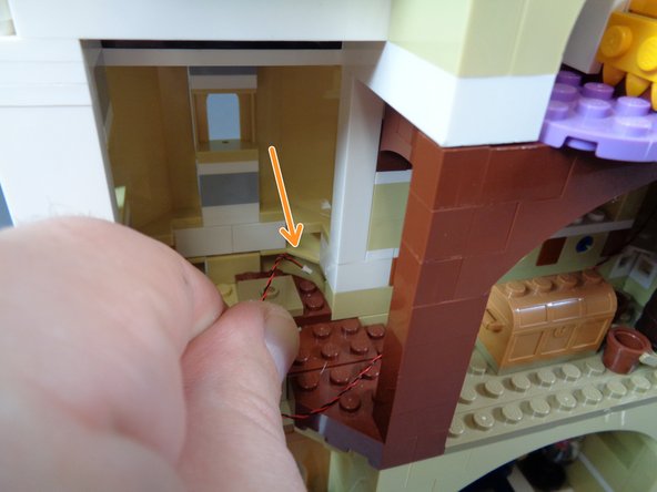
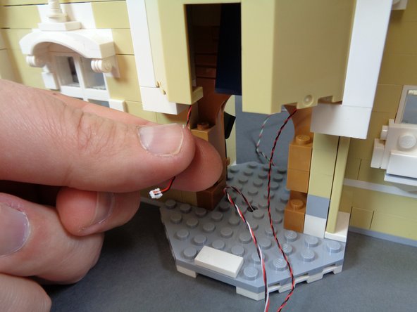
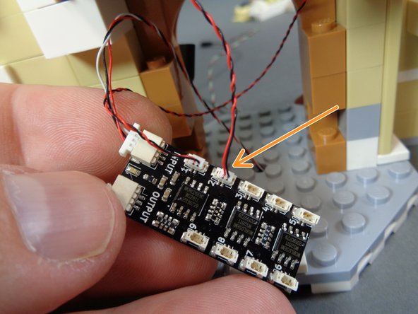
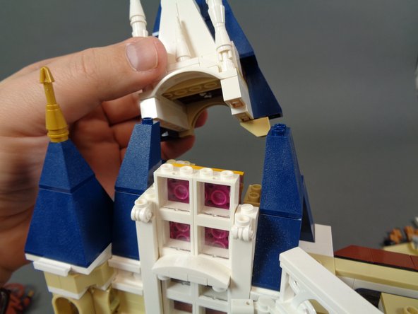
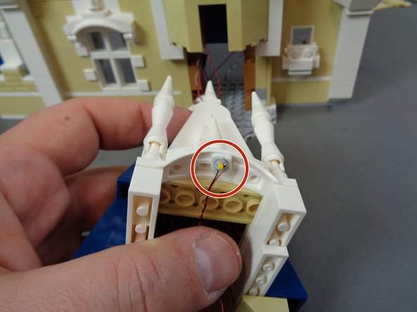
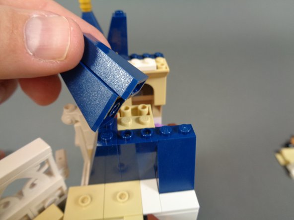
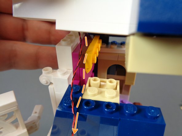
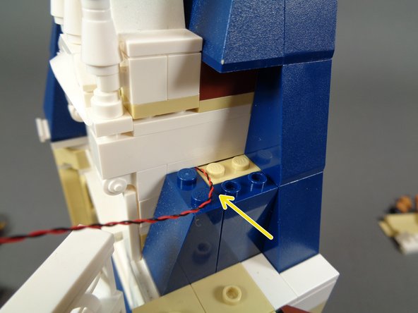
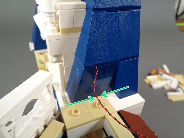
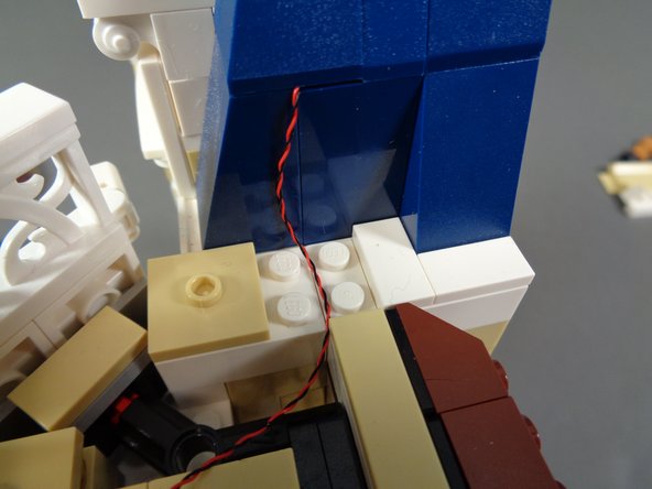
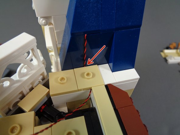
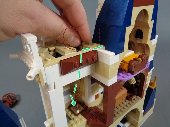
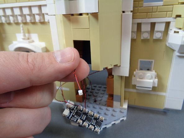
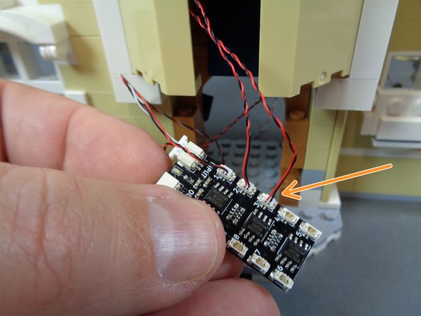
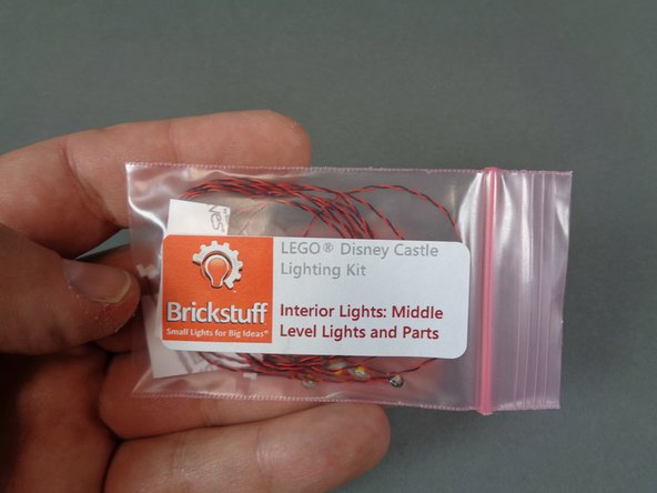
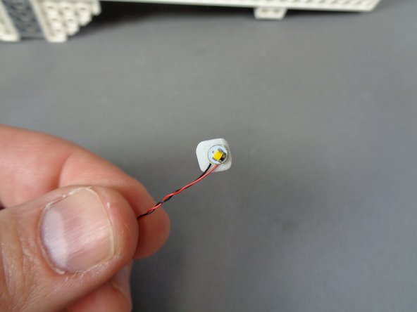
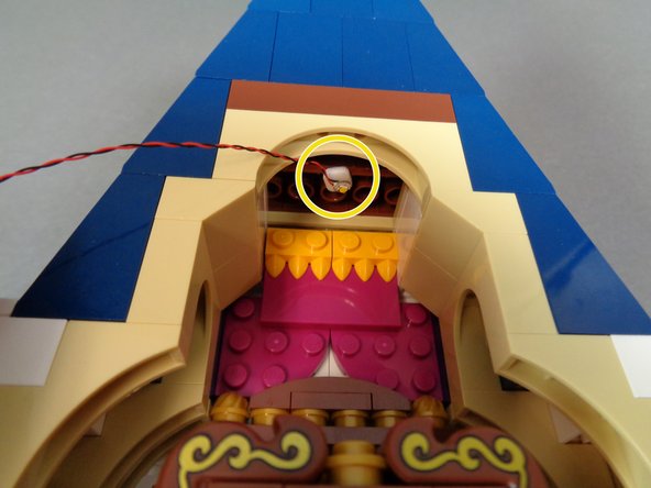
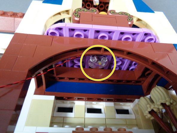
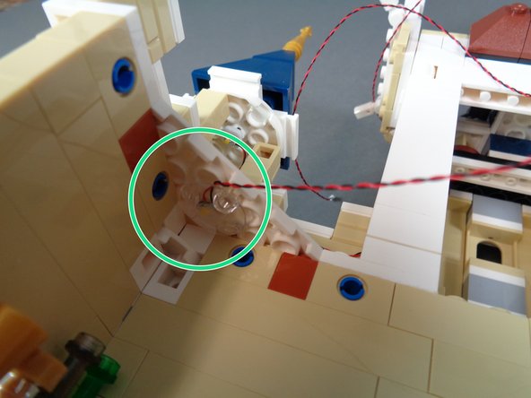
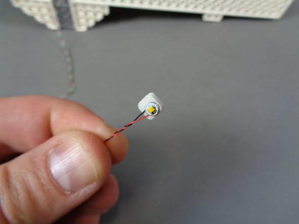
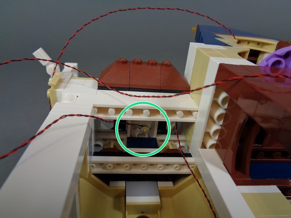
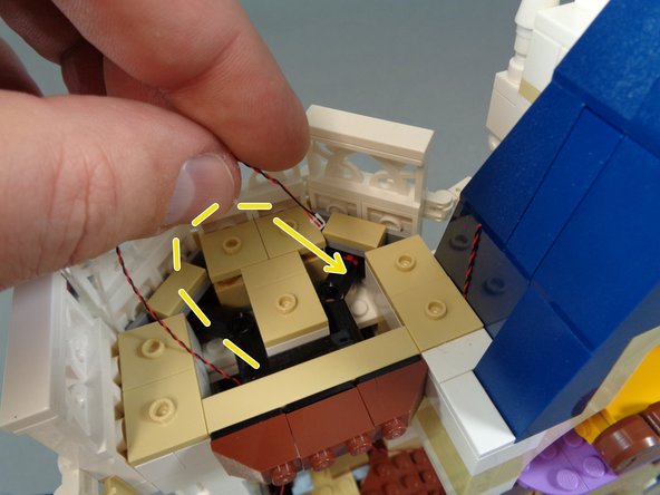
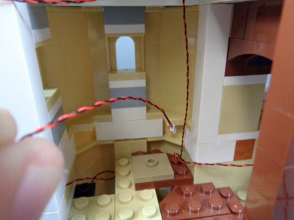
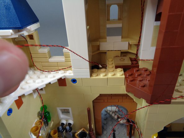
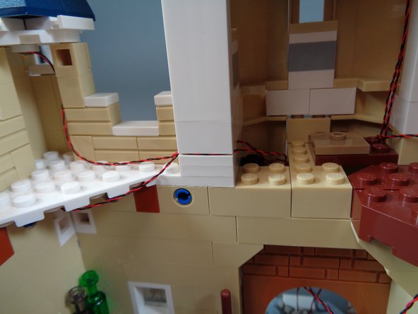
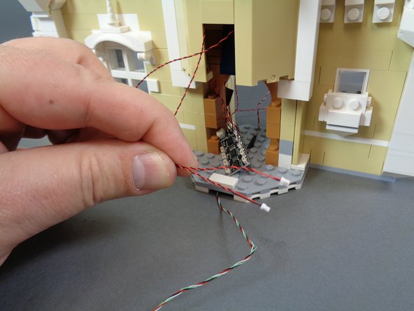
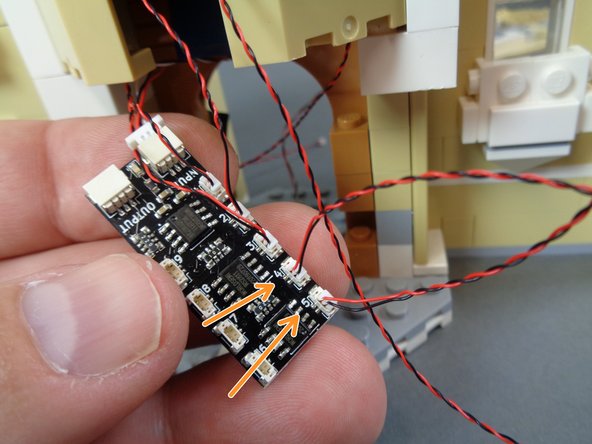
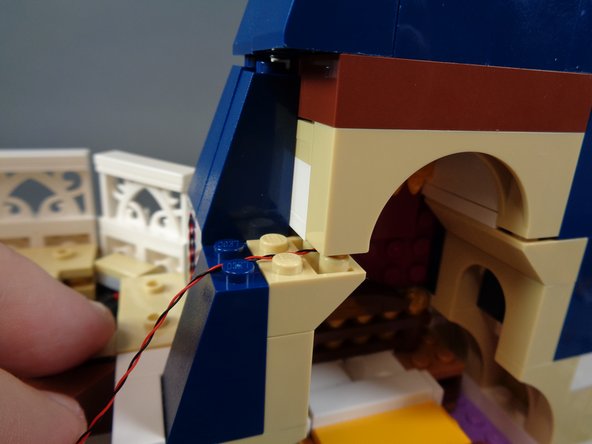
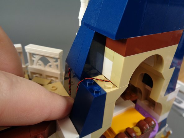
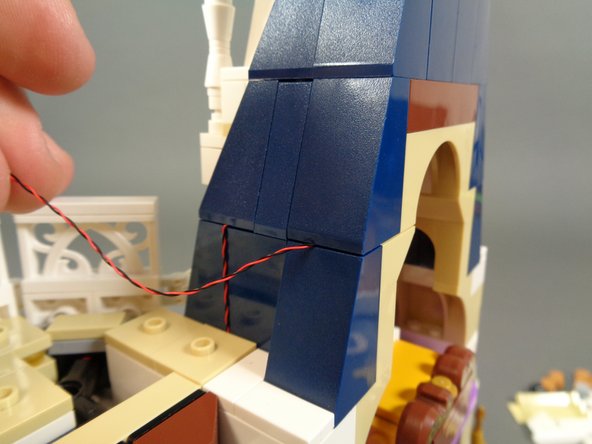
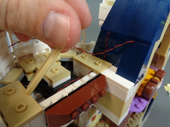
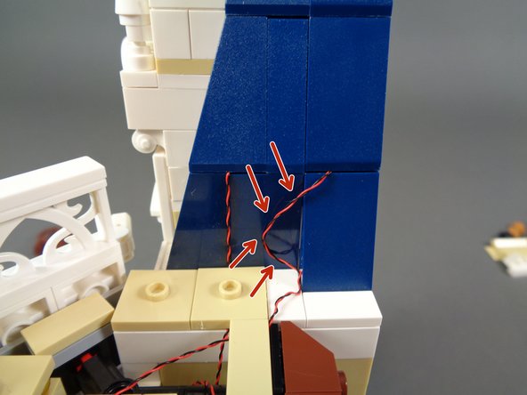
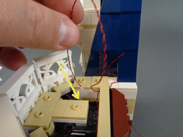
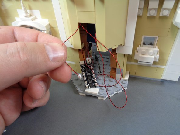
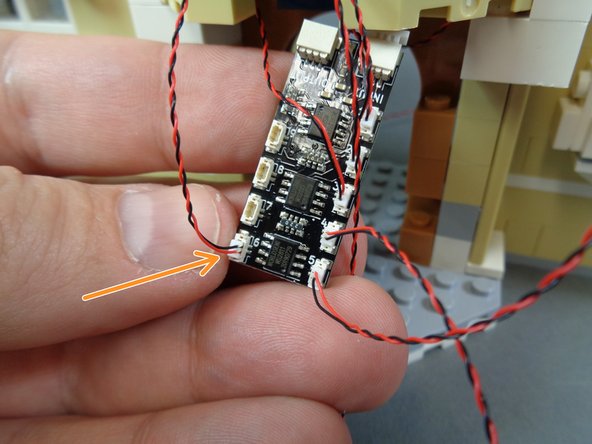
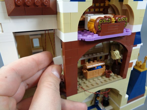
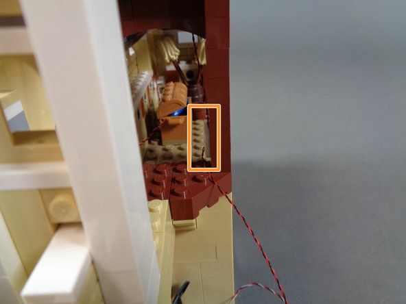
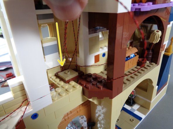
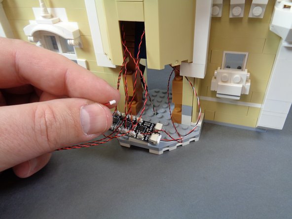
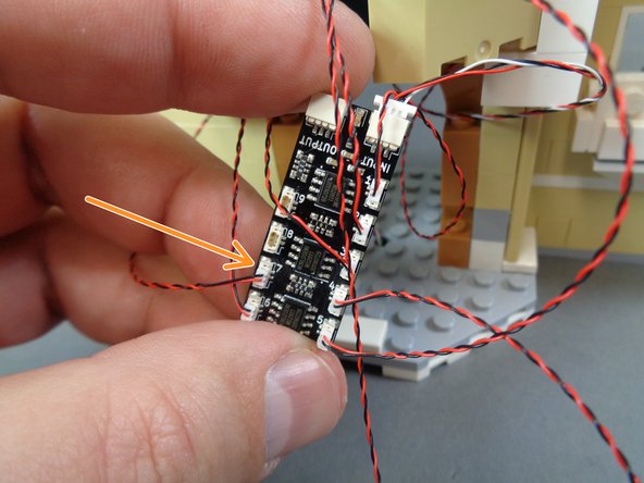
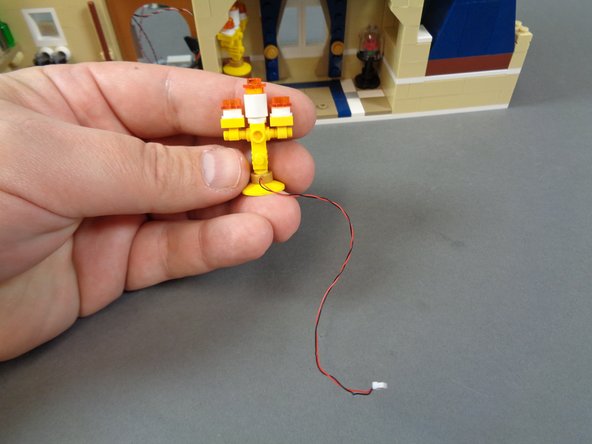
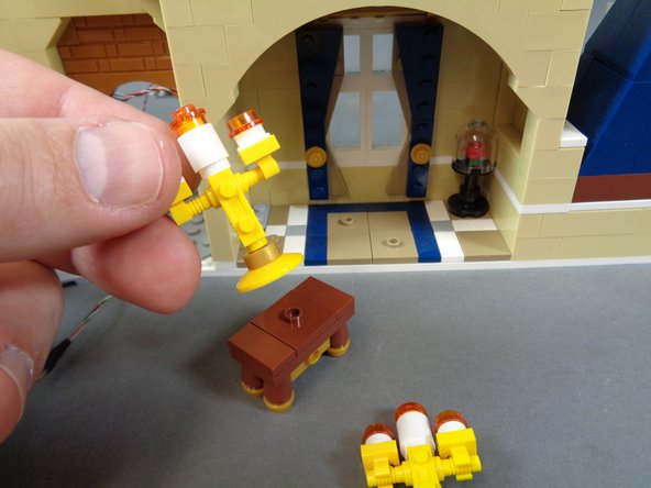
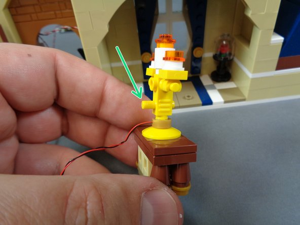
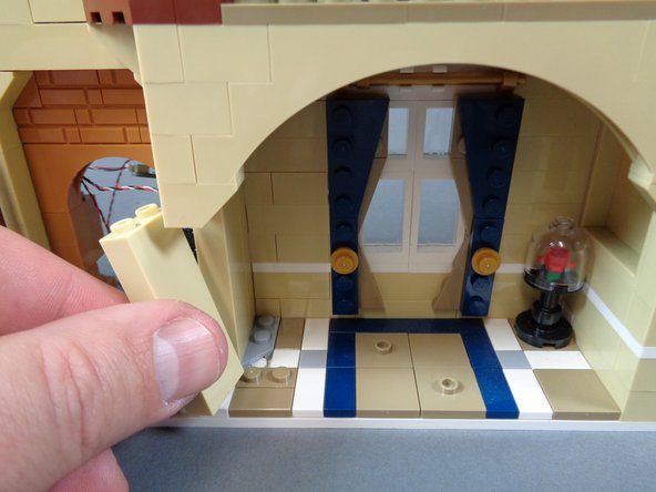
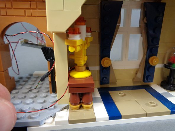
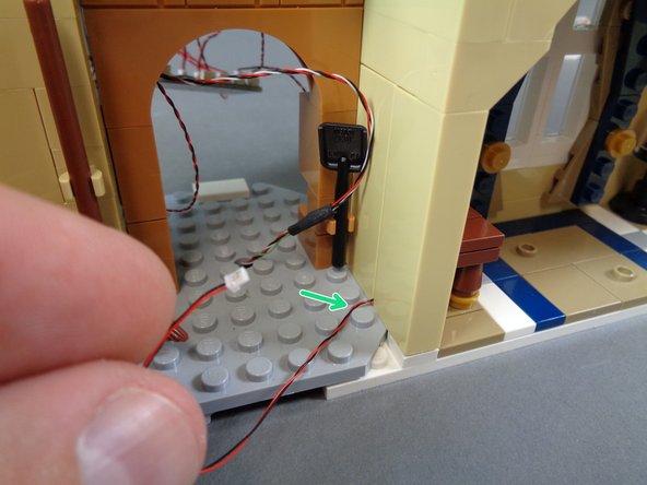
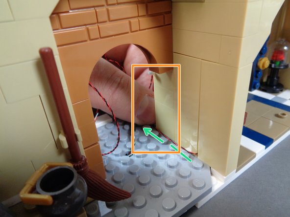
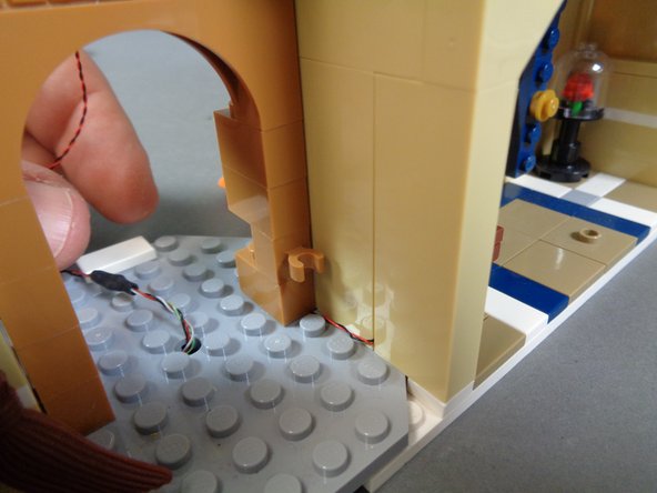
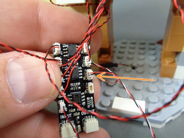
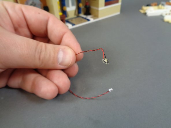
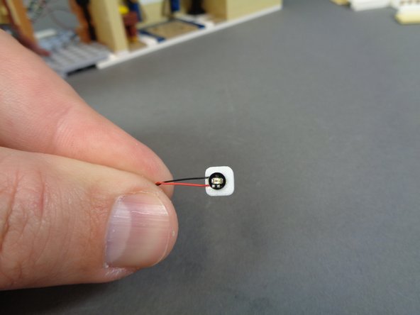
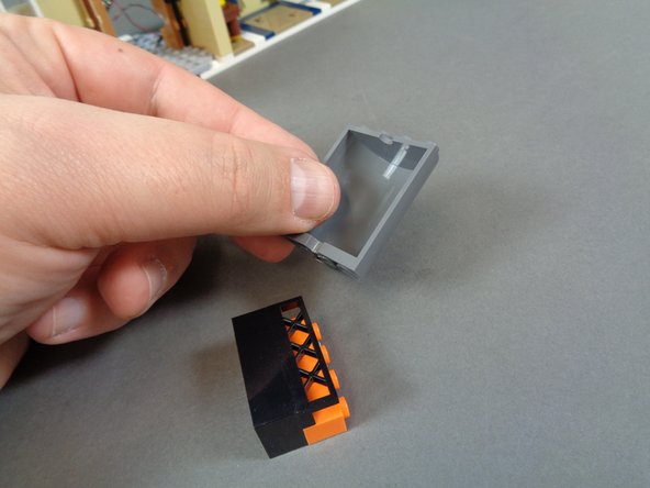
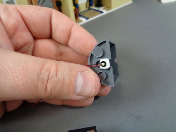
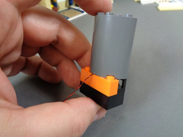
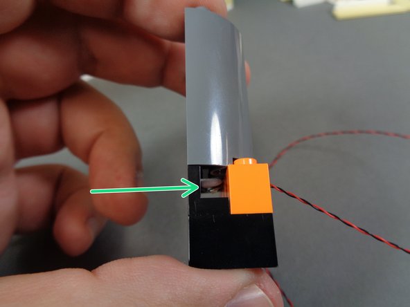
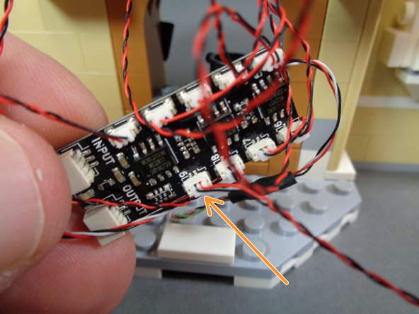
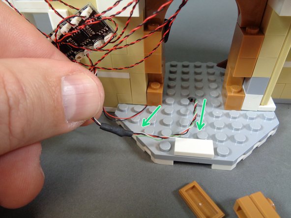
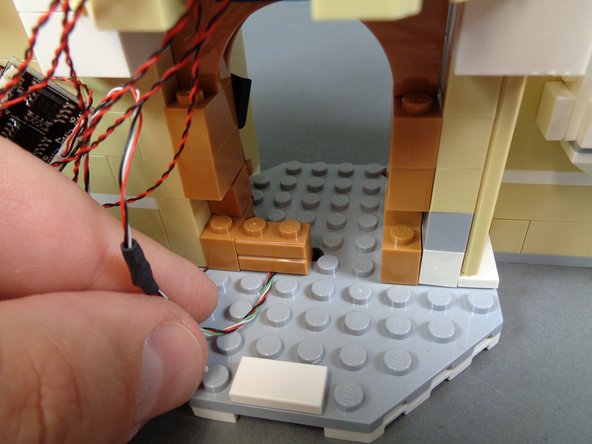
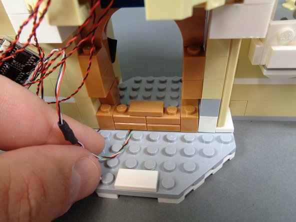
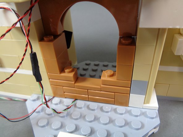
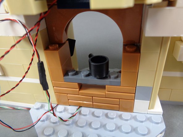
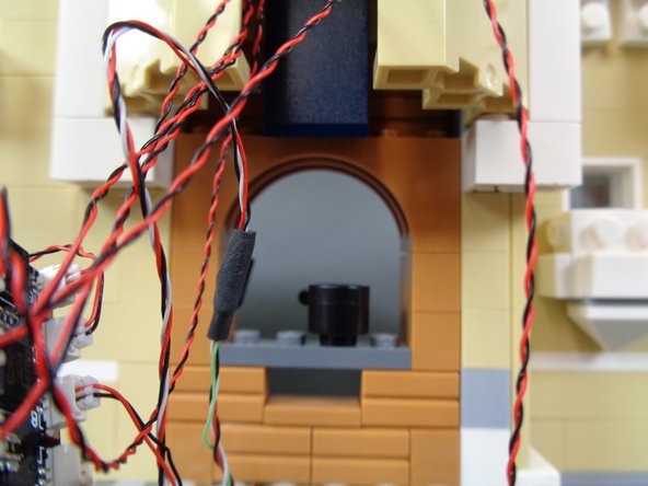
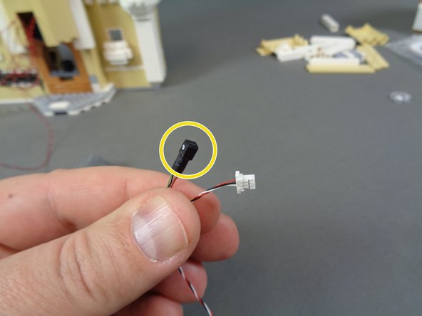
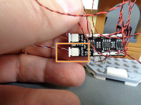
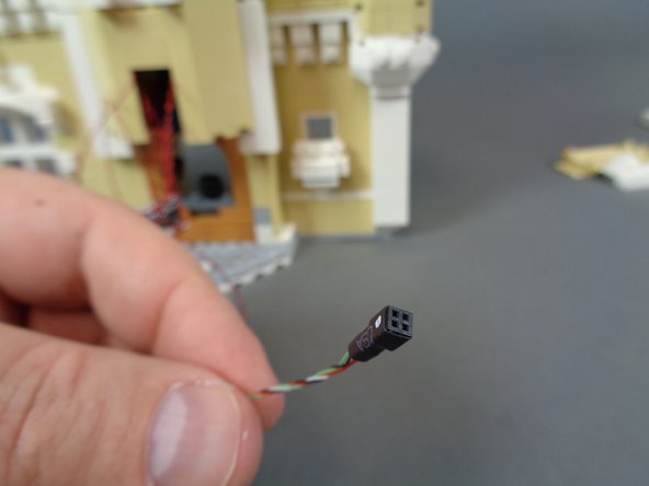
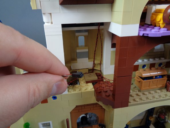
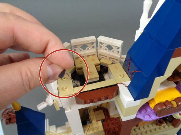
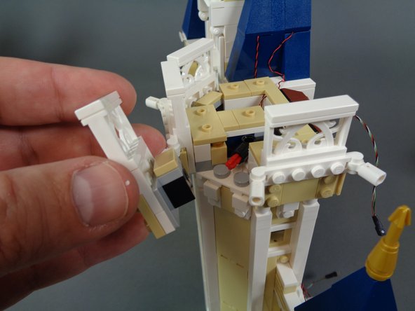
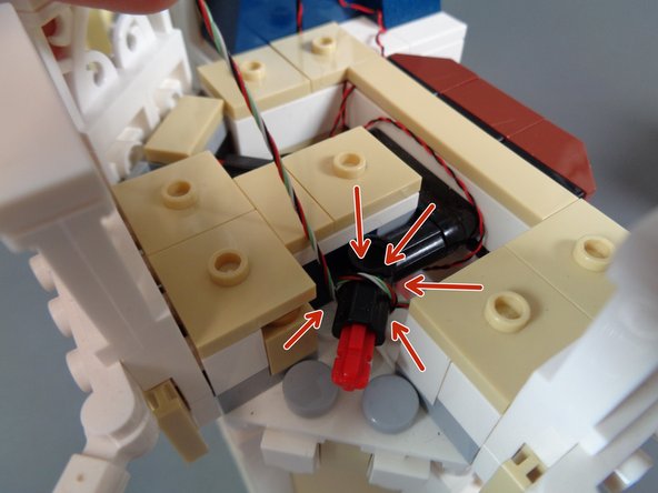
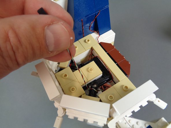
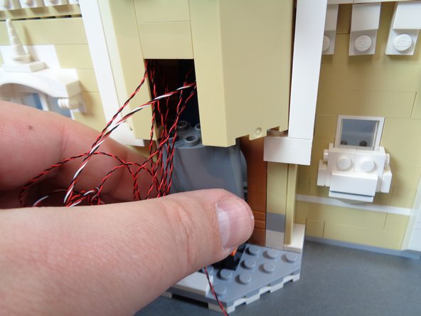
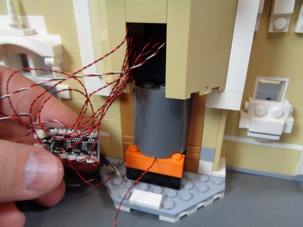
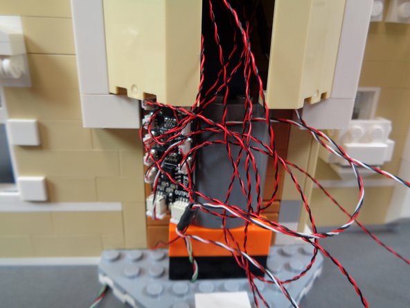
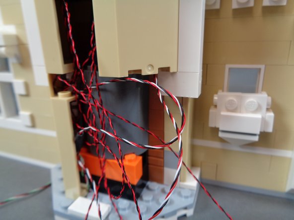
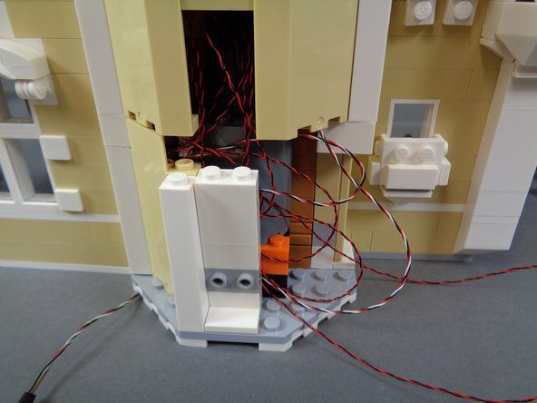
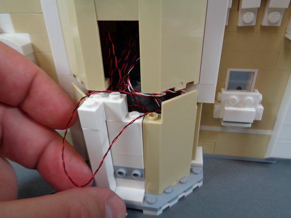
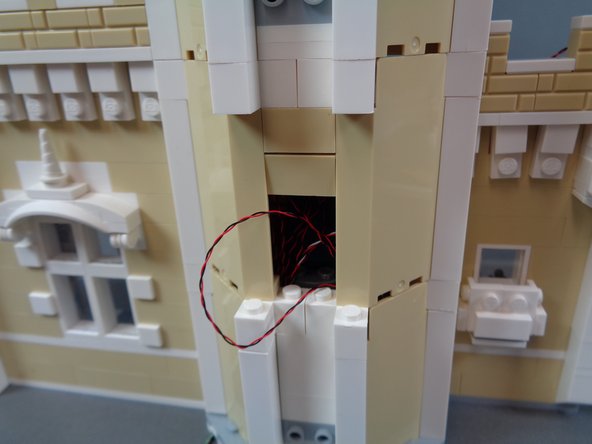
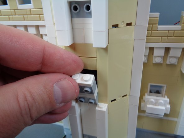
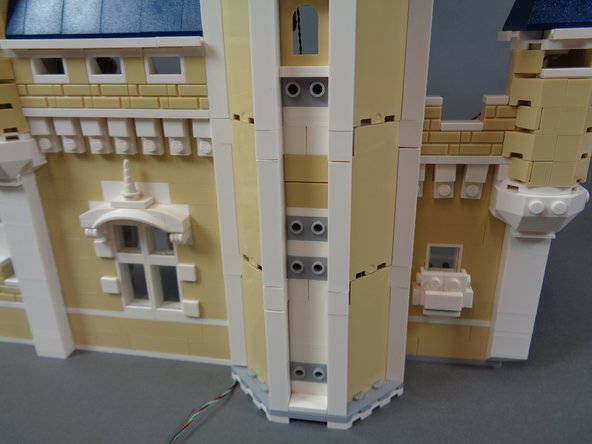
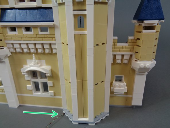
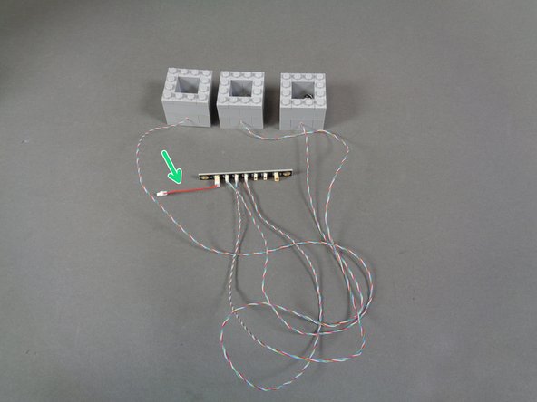
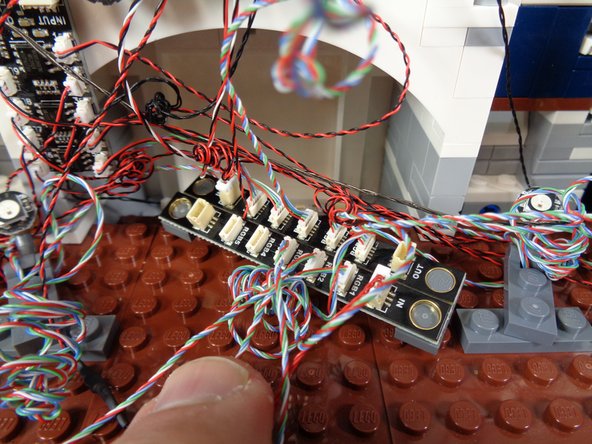
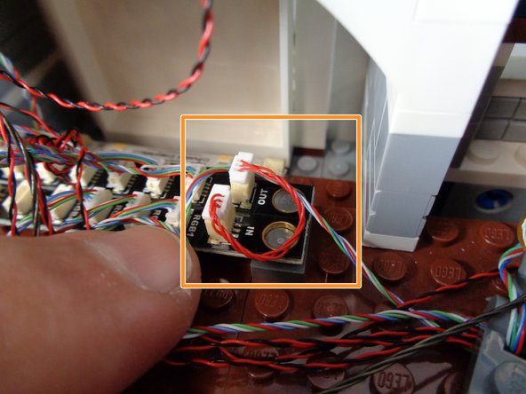
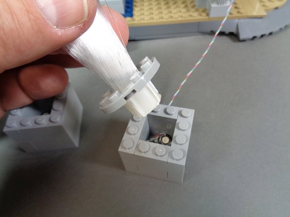
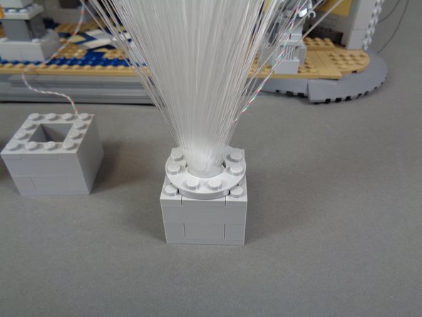
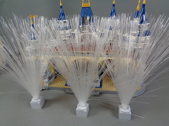

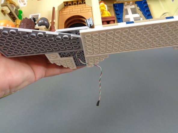
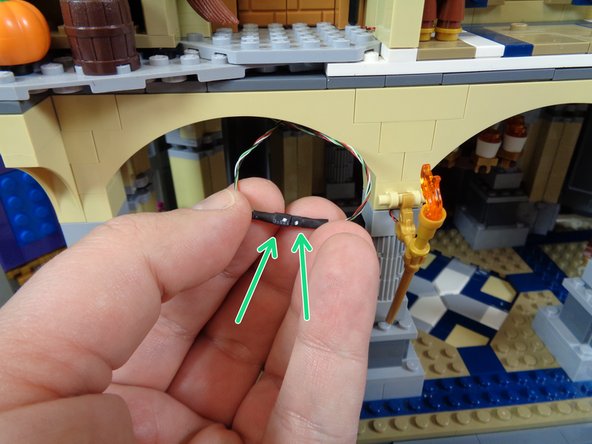
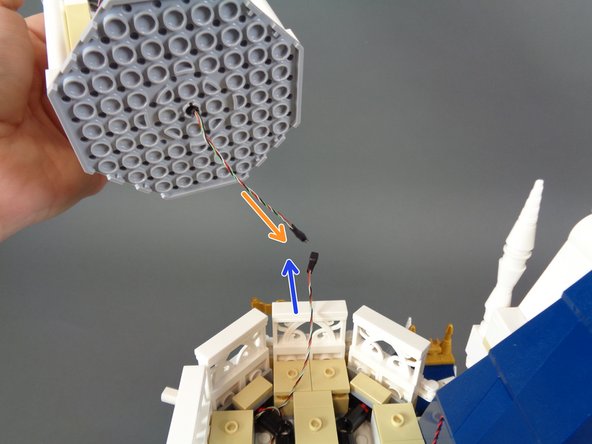
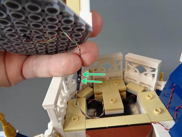
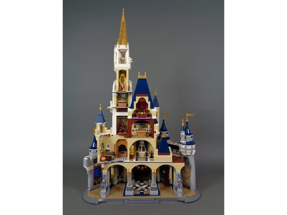
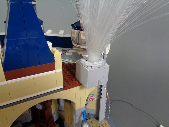
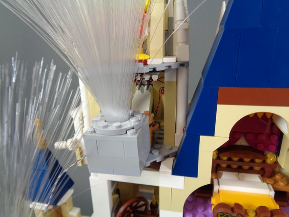
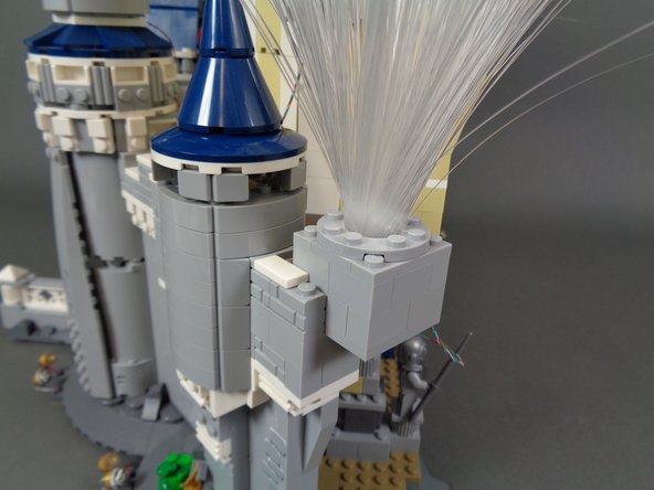
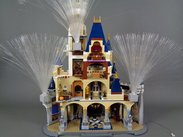
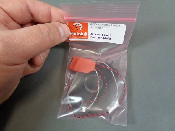
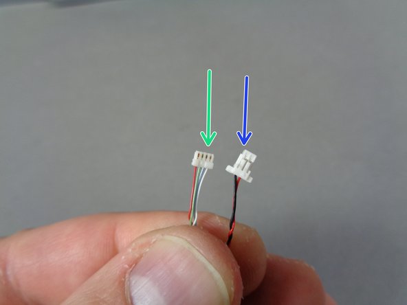
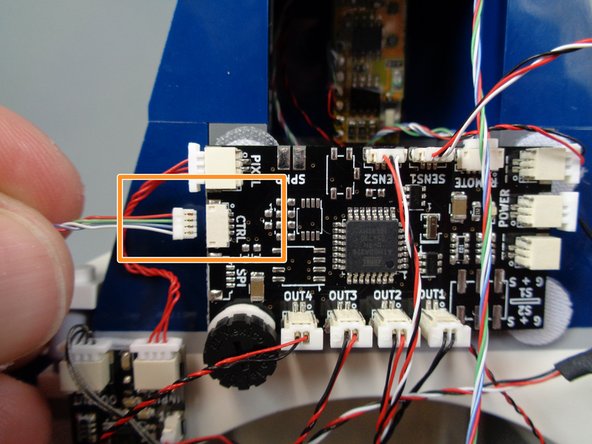
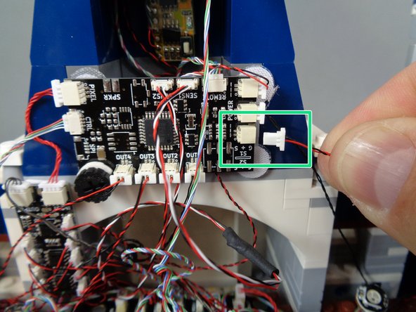
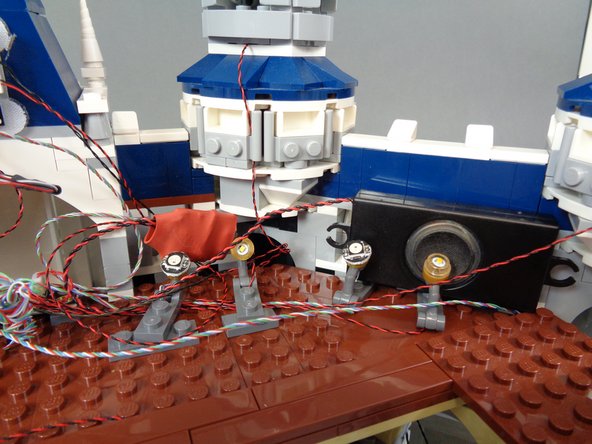
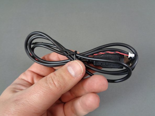
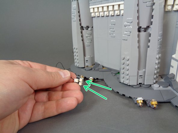
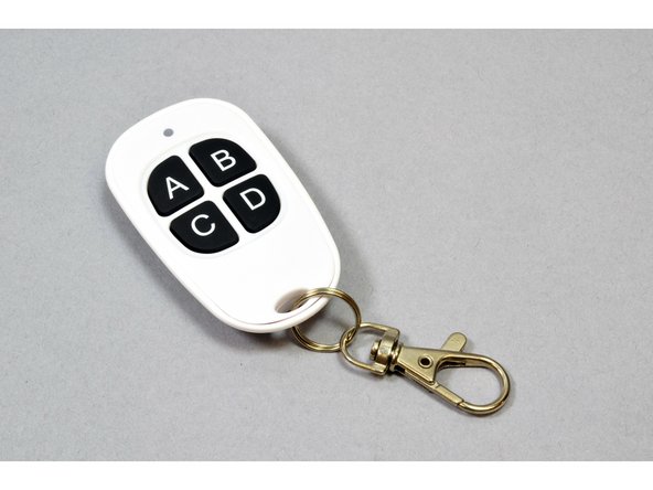

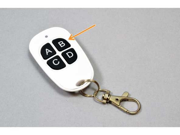
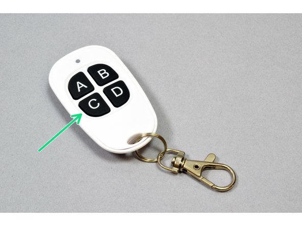
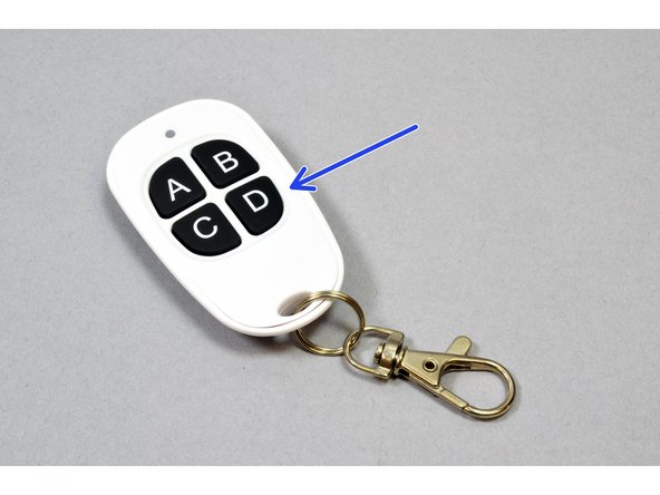
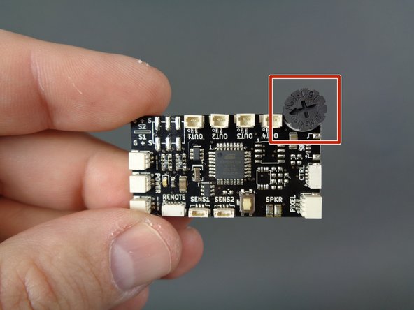
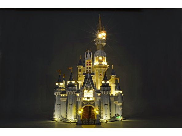
Attached Documents
