
Tools
Parts
-
-
There are several ways to read this guide:
-
Reading it on the web in your browser.
-
Downloading a PDF copy of the guide. You can do this by selecting "Download PDF" as shown by the red rectangle in the first photo. Click on the Options heading in the upper right corner of the screen (see the green rectangle).
-
In the "Dozuki" application, which is available for download from the Apple App Store and various Android and Google marketplaces.
-
If you view this guide in the Dozuki app, search for "Brickstuff" the first time you open the app, then select "Product Guides" from the categories listed under Brickstuff. Scroll down to find this guide.
-
You can also translate this guide into another language when viewing on the web. To do this, install a translator extension into your browser and use that extension/plug-in to translate the page. Using the main Google translate website (translate.google.com) does not work.
-
-
-
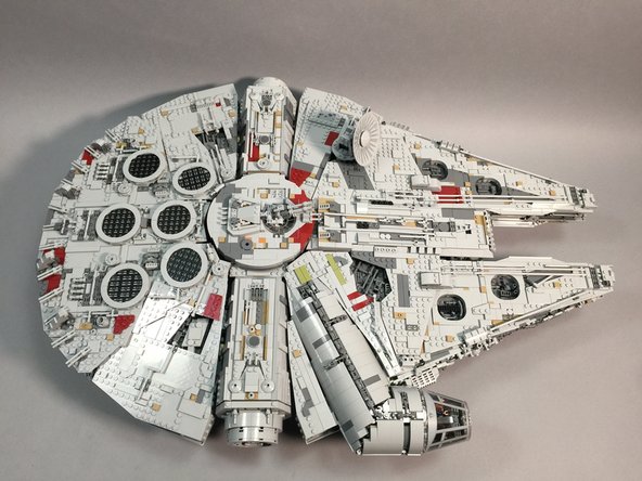
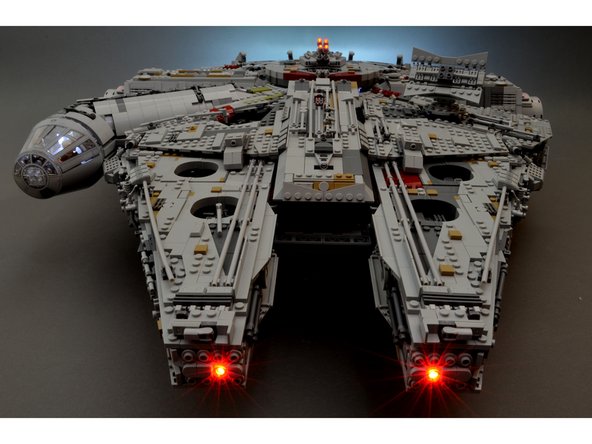
Begin by placing your Millennium Falcon on a large, flat surface. You will need space around the Falcon to remove panels.
-
As shown in the second photo, remove the two right rear panels from the top of the Falcon.
-
-
-
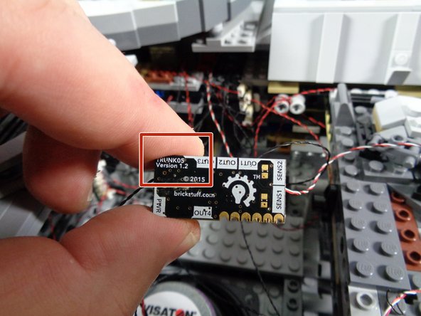
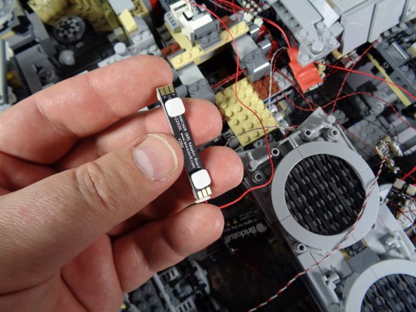
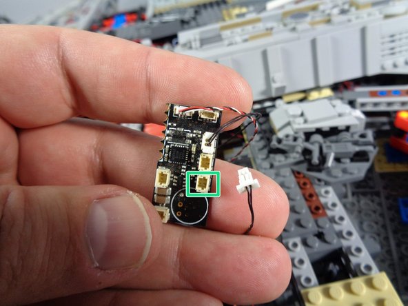
Take the old controller from inside your Falcon and check the version number on the back side. The controller should say TRUNK05 on the back.
-
Leave all wires connected to the controller for now.
-
As shown by the red square, make sure your controller says "Version 1.2" on the back.
-
If your controller does not say Version 1.2, please send us an e-mail to support@brickstuff.com and we will send you a needed adapter board. You will still be able to complete all of the installation steps in this guide. The only part you will not be able to connect without the adapter we will send you is the engines sound module.
-
-
-
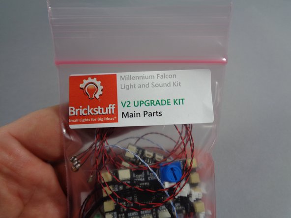
As shown in the photos for this step, open your upgrade kit and remove the pink bag with the label "Main Parts."
-
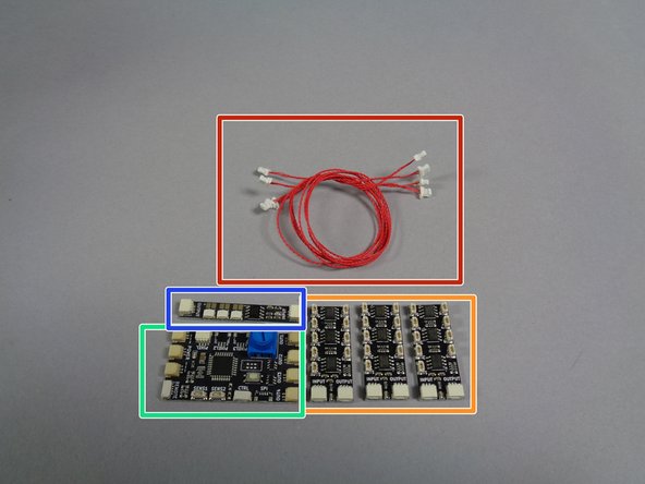
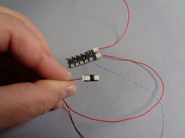
You will remove six pieces from the Main Parts bag:
-
Four red 3-wire connecting cables, as shown by the red rectangle in the second photo.
-
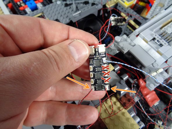
Three adapter boards labeled BRANCH09X on the back, as shown by the orange rectangle in the second photo.
-
One TRUNK08 master controller board, as shown by the green rectangle in the second photo.
-
One adapter board labeled BRANCH09 on the back, as shown by the blue rectangle in the second photo.
-
-
-
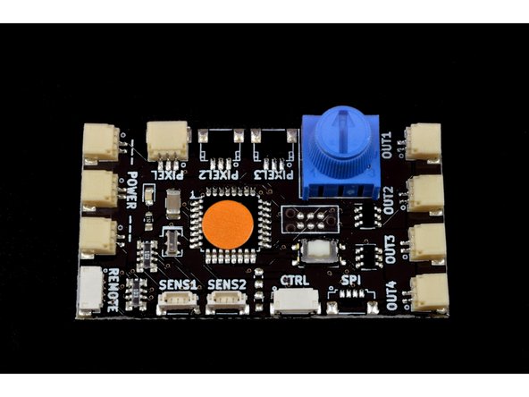
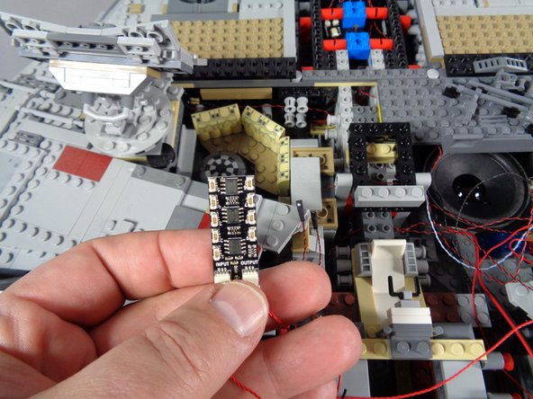
Your TRUNK08 master controller has a special program written to it-- this is customized only for the Falcon upgrade kits. The photo for this step shows the controller, which should have an orange sticker on the board as shown.
-
The rest of the photos in this guide will show the TRUNK08 controller without the orange sticker-- don't worry about this. All of the other connections and operation are the same as for the "non-upgrade" version of the controller.
-
-
-
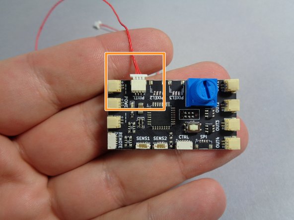
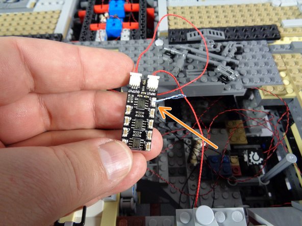
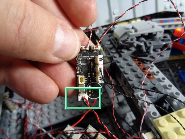
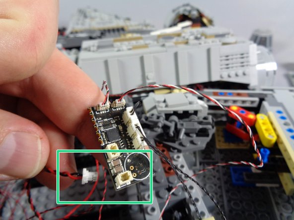
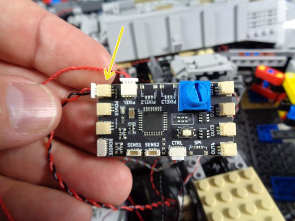
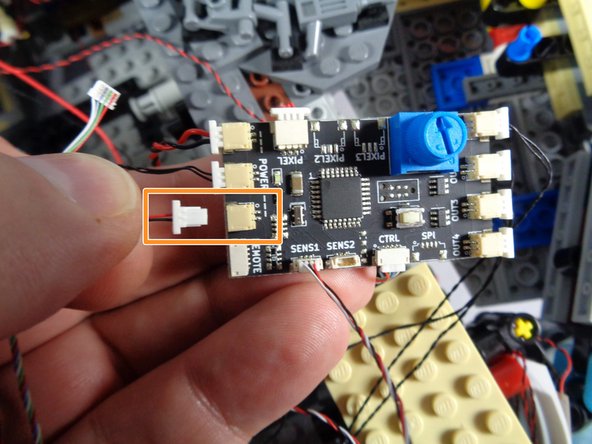
Take one of the red connecting cables and plug one end of the cable into the PIXEL (or PIXEL1) plug on the TRUNK08 master controller board, as shown by the orange square in the photo.
-
It is likely that the PIXEL2 and PIXEL3 connectors on your TRUNK08 do not have a plug attached-- this is ok. You will only be using the plug labeled PIXEL or PIXEL1.
-
-
-
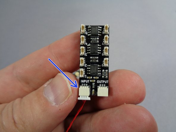
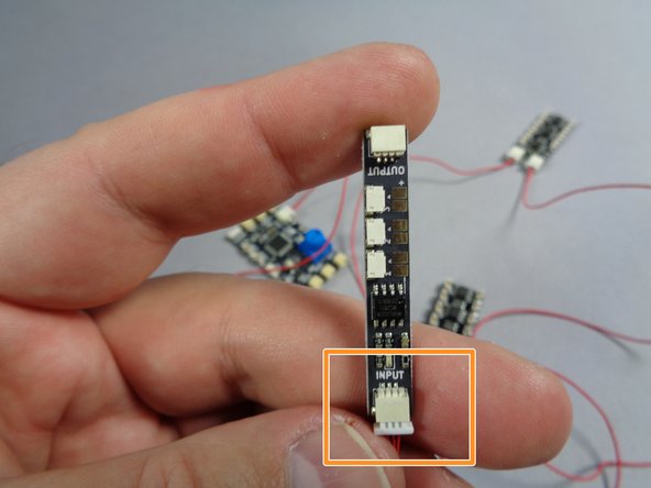
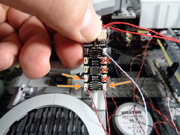
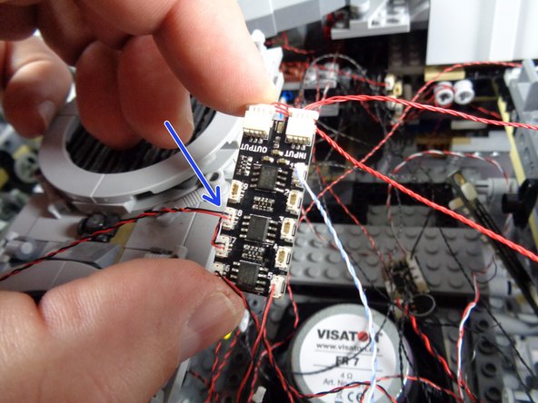
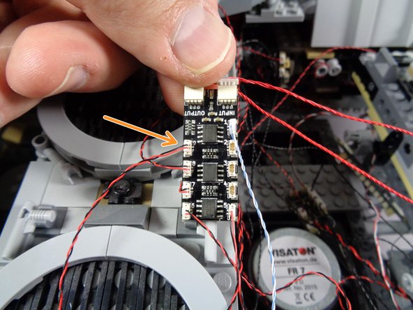
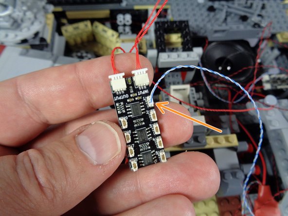
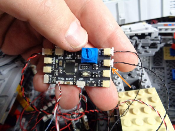
As shown by the blue arrow in the first photo for this step, connect the other end of the red cable from the TRUNK08 controller to the INPUT plug on one of the BRANCH09X adapters.
-
In order for your kit to function correctly, it is critical that you connect the INPUT and OUTPUT plugs as shown, so that the OUTPUT from one adapter is connected to the INPUT on the next. If you connect an OUTPUT to an OUTPUT or an INPUT to an INPUT, the green power light will still turn on, but the connected lights will not work.
-
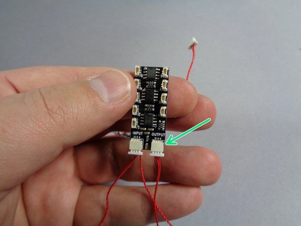
After you have connected the red cable to the INPUT plug of the BRANCH09X adapter as shown in the first photo, connect a second red cable to the OUTPUT plug as shown by the green arrow in the second photo.
-
-
-
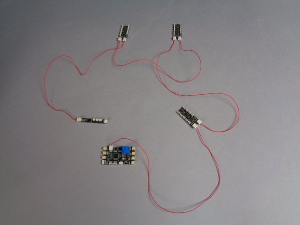
After you have connected the TRUNK08 master controller to the first BRANCH09X adapter board, connect the OUTPUT of the first BRANCH09X to the INPUT of the second BRANCH09X.
-
Next, connect the OUTPUT of the second BRANCH09X to the INPUT of the third BRANCH09X.
-
Finally, connect the OUTPUT of the third BRANCH09X to the INPUT of the BRANCH09 adapter as shown by the orange rectangle in the second photo.
-
Before continuing, make sure you have all adapters connected correctly, with the OUTPUT of one connected to the INPUT of the next.
-
As a final check, make sure the OUTPUT plug of the BRANCH09 adapter board (in the second photo) does NOT have a cable connected to it. This OUTPUT plug on the BRANCH09 adapter board should be left unconnected.
-
This is one of the most important parts of the installation: if any INPUT or OUTPUT plugs are reversed, the power lights on all adapter boards will still turn on, but any connected lights will not work.
-
-
-
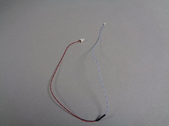
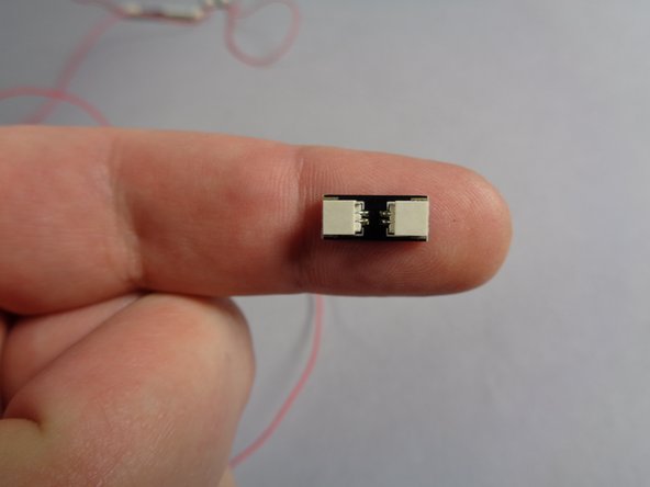
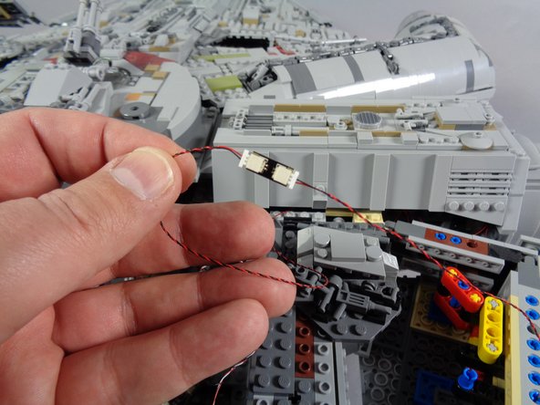
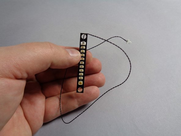
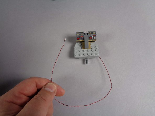
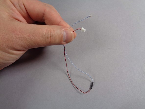
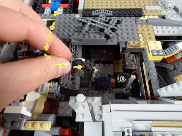
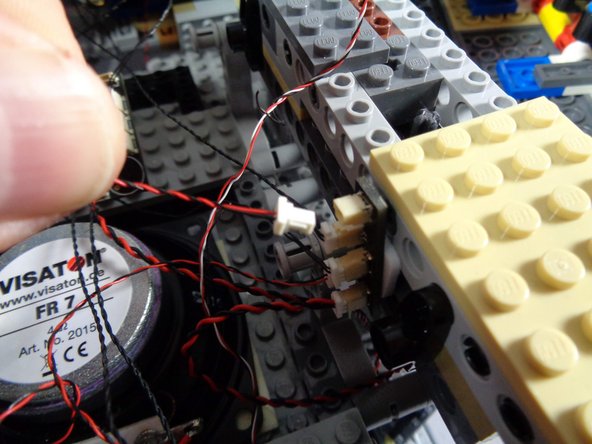
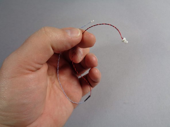
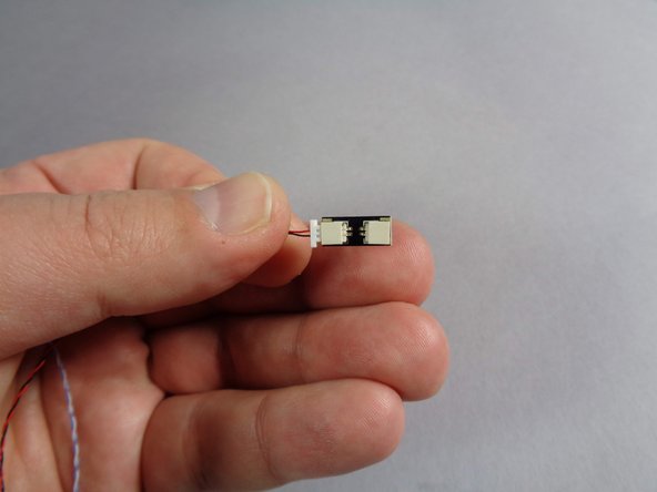
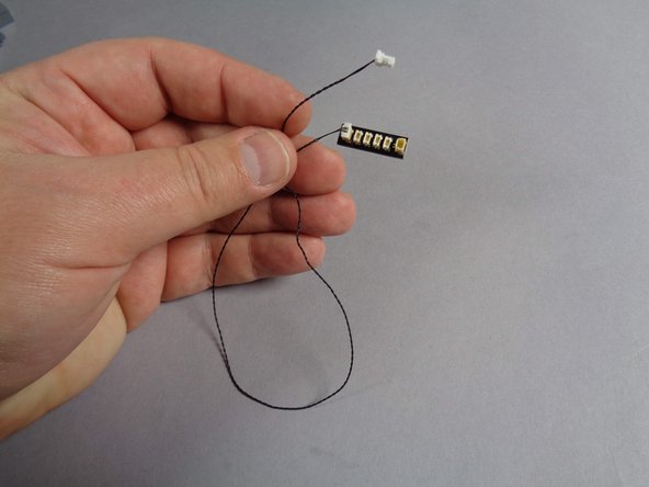
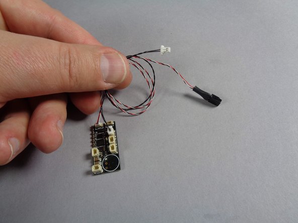
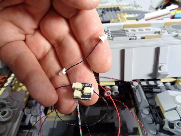
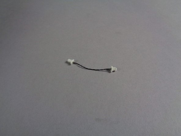
Inside the Main Parts bag, there will be two cables like the one shown in the first photo.
-
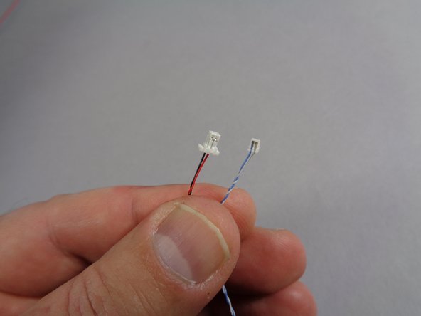
These cables have a large plug on one end and a small plug on the other end. See the second photo for the size comparison close up.
-
Take one of the cables out of the Main Parts bag, and leave the other one in the bag for later.
-
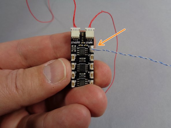
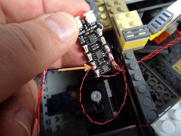
As shown by the orange arrow in the third photo, connect the small plug to connector #1 on the first BRANCH09X adapter board. This will be the adapter that is closest to the TRUNK08 master controller.
-
Be careful when inserting plugs-- they will connect in only one direction. Do not force plugs! When inserting, press straight down and not to one side, or the connector can crack.
-
-
-
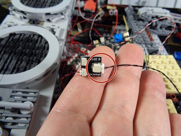
Also inside the Main Parts bag, there will be two adapters like the one shown in the first photo for this step. These have two large plugs, one on either end, and are labeled BRANCH13 on the back.
-
Remove one of these adapters from the Main Parts bag, and leave the other one in the bag for later.
-
As shown in the second photo, connect the large end of the cable you used in the last step to one of the two plugs on the adapter board. It does not matter which of the two plugs you connect the cable to.
-
-
-
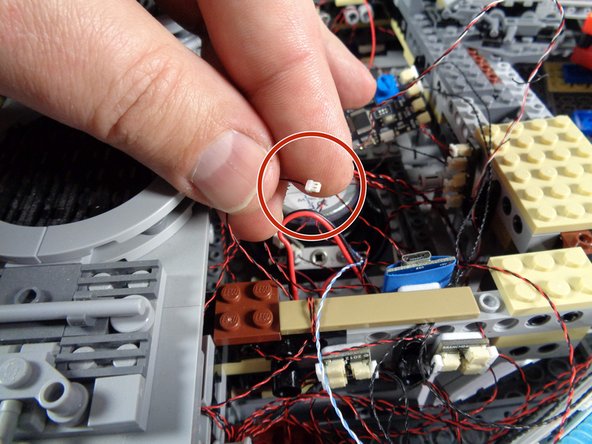
Now you will disconnect the 4-light docking bay LED assembly from its power plug, and connect it to the BRANCH13 adapter from the previous step.
-
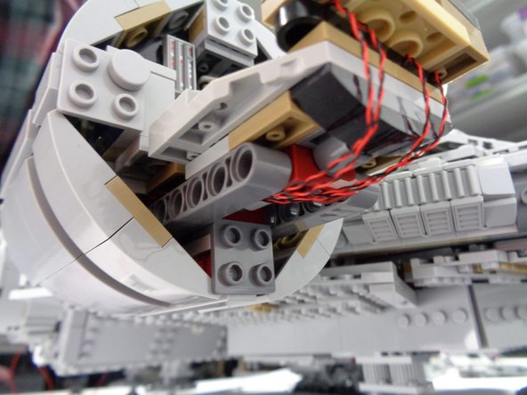
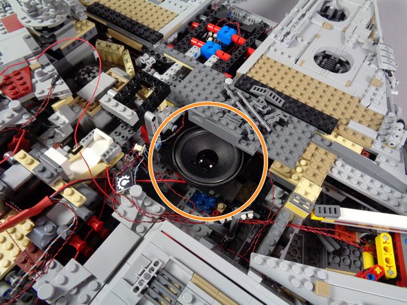
The first photo in this step shows the docking bay light assembly from when you first installed your Falcon lighting kit. That was probably a long time ago, so we wanted to show the photo of what the assembly looked like. You do not need to remove the assembly now-- this photo is just to remind you.
-
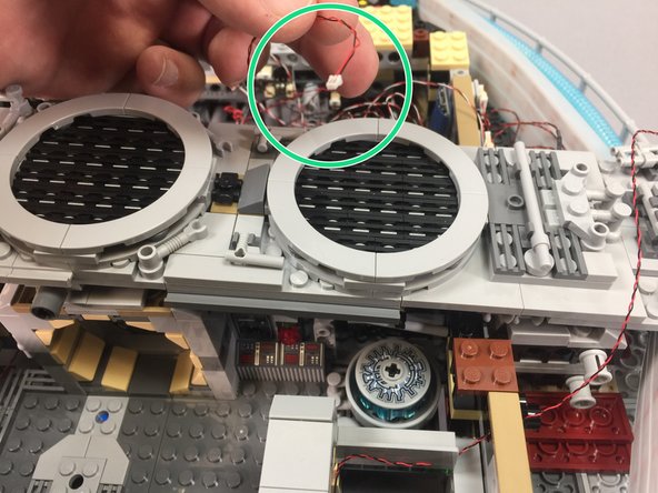
On the inside right rear of your Falcon, just behind the area where the boarding ramp is located, there should be an adapter with multiple large plugs.
-
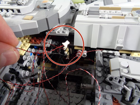
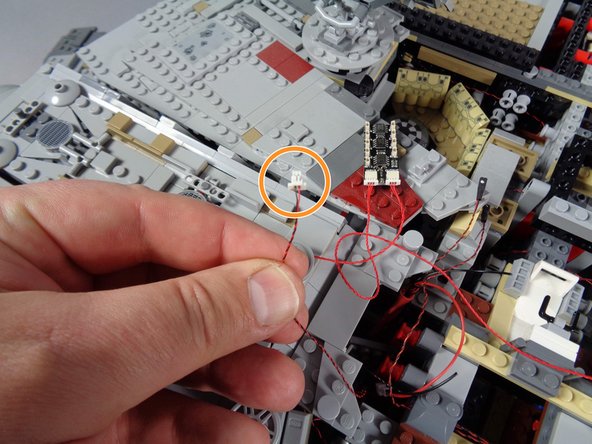
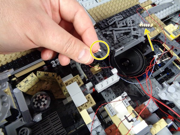
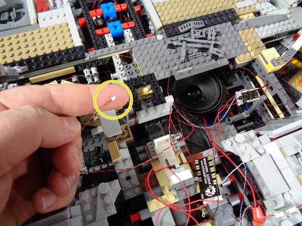
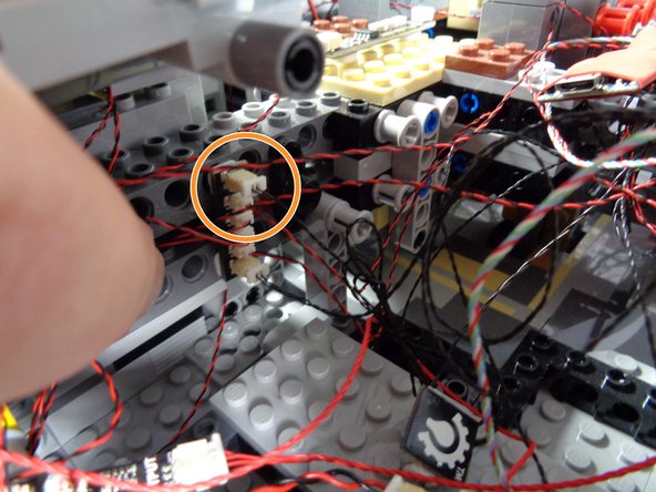
One of these plugs will run back to the 4-light docking bay assembly. This is the plug you want to carefully disconnect from its current socket. To remove the plug, pull using the white tabs-- do not pull by the wire!
-
The red circle in the second photo shows the docking bay assembly plug after it has been disconnected from the old adapter.
-
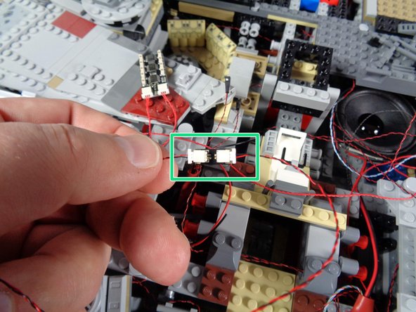
As shown in the third photo, once you have disconnected the docking bay lighting assembly, re-connect the plug to the open connector on the BRANCH13 adapter board you connected in the last step.
-
Your docking bay lighting assembly should now be connected through the BRANCH13 adapter board to plug #1 on the BRANCH09X adapter board.
-
-
-
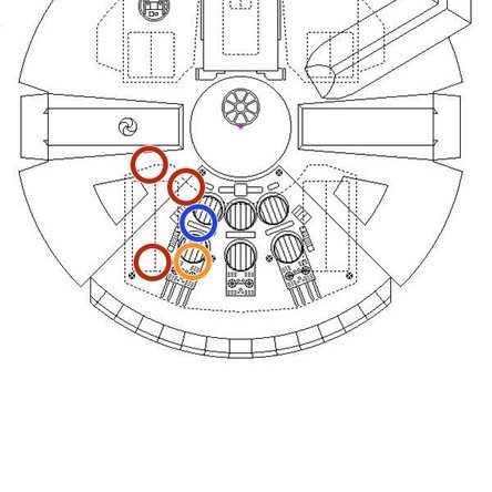
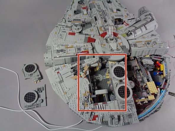
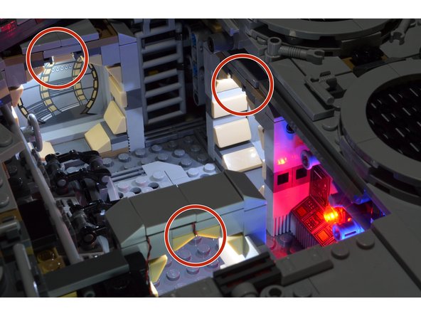
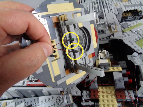
Next, you will disconnect the five lights inside the rear left compartment, including the hyperdrive. The colored circles in the Falcon drawing show where these lights are located.
-
One hyperdrive
-
Three doorway lights
-
One control panel light
-
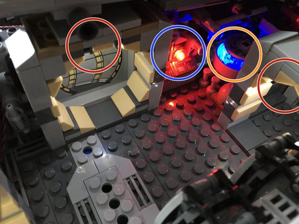
The second and third photos show the interior of the Falcon with these same lights circled.
-
During the next steps, you will disconnect all five of these lights, replace one, and re-connect them to specific plugs in your new kit.
-
-
-
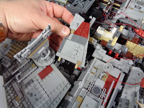
As shown by the red rectangle , remove the left rear panels from your Falcon, so the interior area is visible.
-
-
-
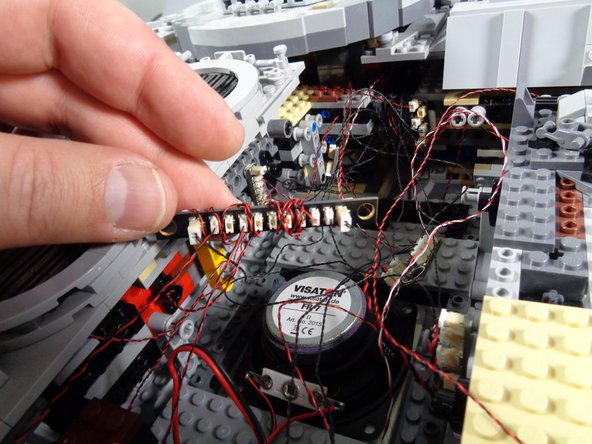
The first photo in this step shows the BRANCH10 adapter board in the right rear section of your Falcon. This is where the five interior lights should be connected, from when you first installed your original light and sound kit.
-
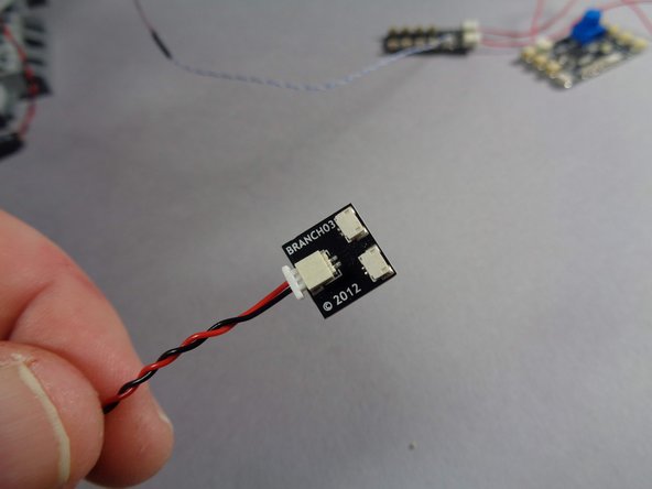
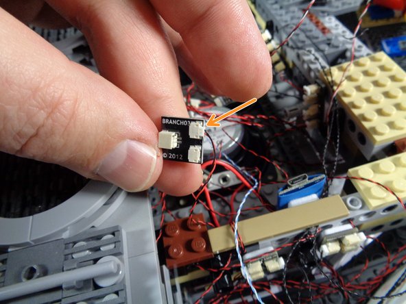
Inside the Main Parts bag for your new kit, there will be an adapter board labeled BRANCH03. This adapter board is shown in the second photo for this step.
-
As shown in the second photo, connect one of the two main power supplies for your Falcon light and sound kit to the large plug on the BRANCH03 adapter, and turn the power supply on. You will use the BRANCH03 adapter to identify each of the five lights you will disconnect.
-
As shown in the third photo, carefully disconnect each of the five lights from the BRANCH10 adapter board one at a time, then connect to one of the small plugs on the BRANCH03 adapter. This should make the light turn on, and you will be able to identify which light each plug matches to.
-
-
-
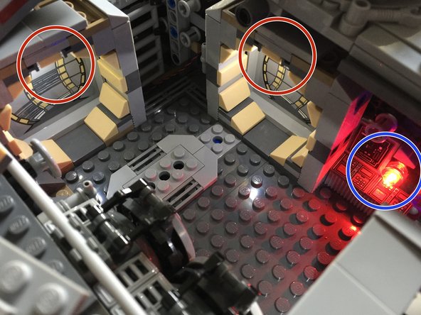
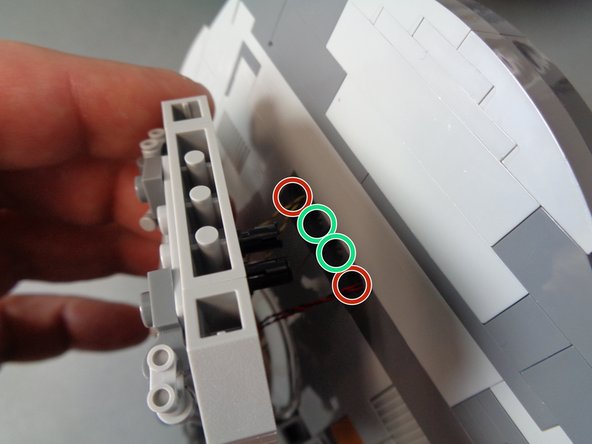
Using the BRANCH03 adapter board connected to your Falcon power supply with the power turned on, test each of the five lights you disconnected to find the three doorway lights. These are shown by the three red circles in the photo.
-
Tie these wires together, so you can keep track of them for the next step.
-
-
-
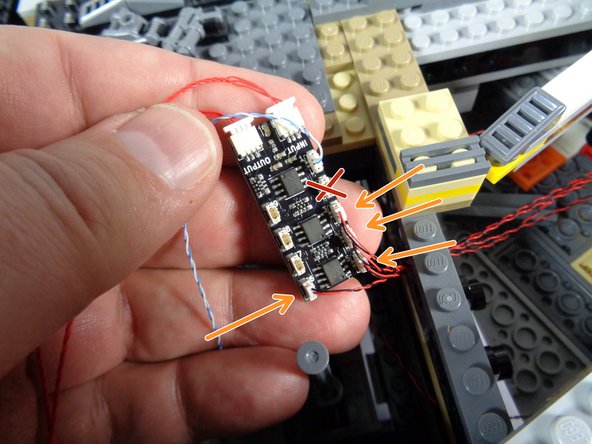
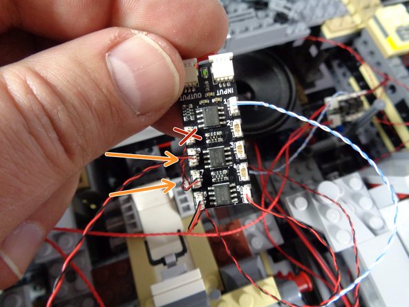
As shown in the photo, carefully connect the three doorway lights to plugs 5, 6, and 7 on the BRANCH09X adapter (the same one you connected the docking bay lights to earlier).
-
As shown by the three red "X" marks in the photo, plugs 2,3, and 4 on the BRANCH09X adapter will be empty. This is ok.
-
It does not matter which doorway light you connect to plug 5, 6, or 7. Just make sure to only use these three specific plugs on the BRANCH09X adapter board.
-
-
-
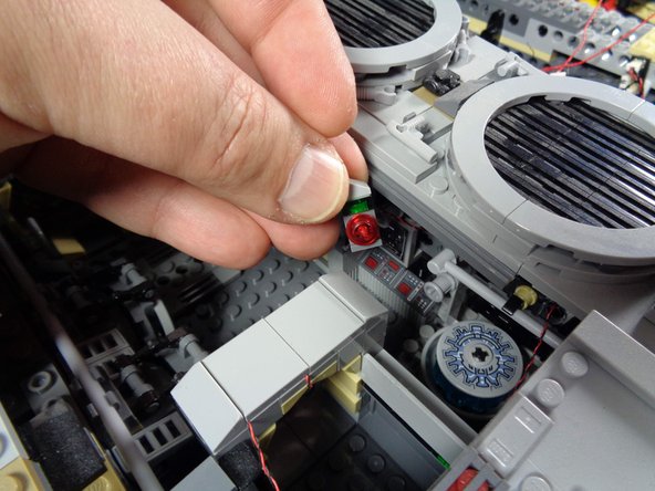
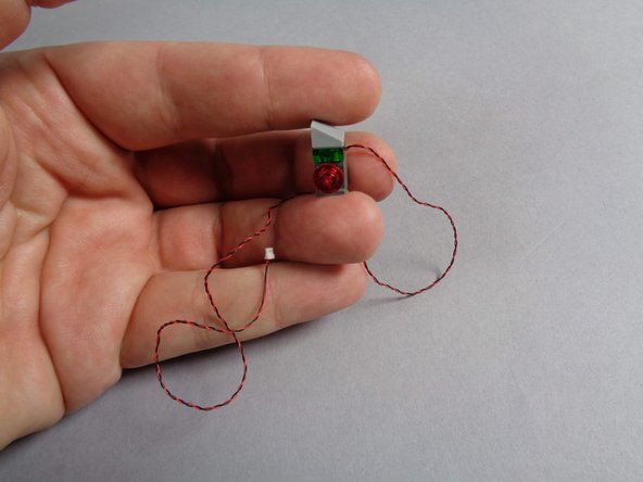
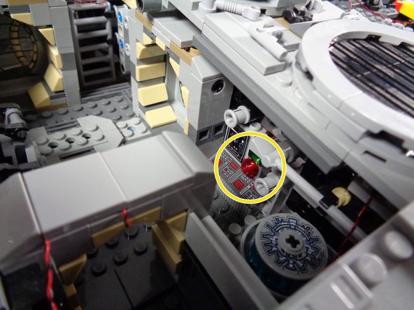
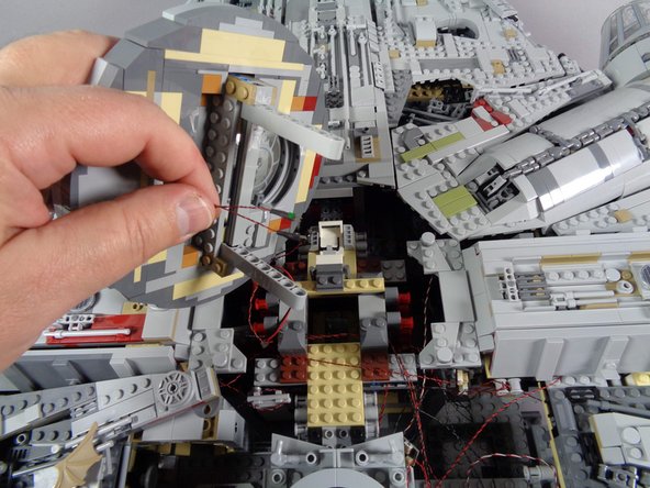
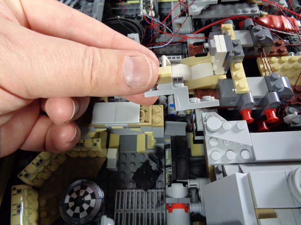
Next, you will remove the control panel brick from the area next to the hyperdrive, as shown in the first photo.
-
The second photo shows the control panel and light wire removed from the Falcon.
-
As shown in the third photo, remove the transparent plate covering the LED light, and remove the old light.
-
You will not need this light any longer, and can set it aside or use it in a different lighting project.
-
-
-
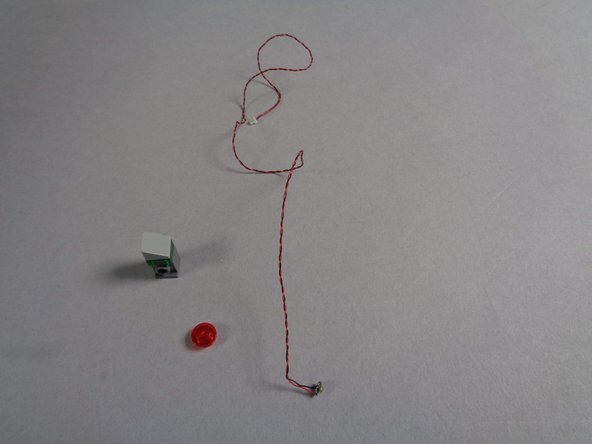
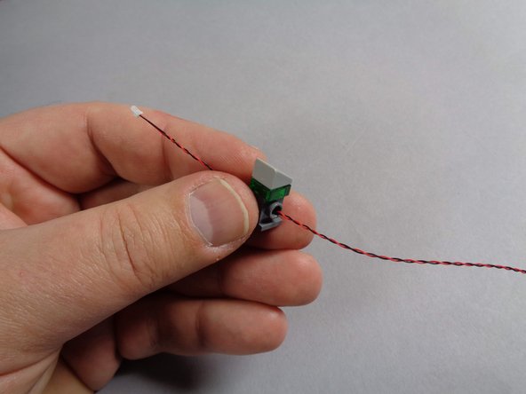
Inside the Main Parts bag, there will be four cool white Pico LED lights with 12" (30.4cm) cables. Take one of these and feed the LED light wire through the hole in the control panel brick as shown in the first photo.
-
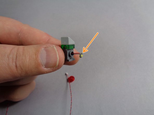
As shown by the orange arrow in the second photo for this step, carefully bend the round LED light board so it will sit flat on top of the hole in the brick.
-
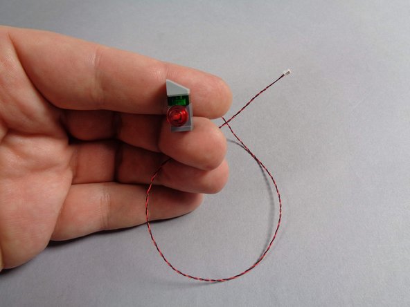
Replace the transparent red round plate as shown in the third photo. You should now have a re-assembled control panel with one of the new cool white Pico LED lights inside.
-
-
-
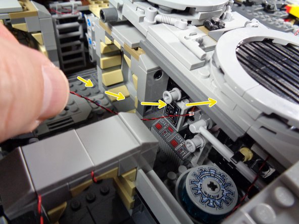
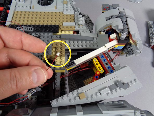
As shown by the yellow arrows and circle in the first and second photos for this step, pass the LED light wire through the wall, and re-attach the control panel brick.
-
You should now have the LED light wire extending into the area near the BRANCH09X adapter board.
-
As shown by the blue arrow in the third photo, carefully connect the new control panel LED light to plug #8 on the BRANCH09X adapter board.
-
-
-
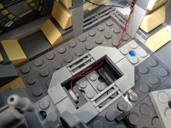
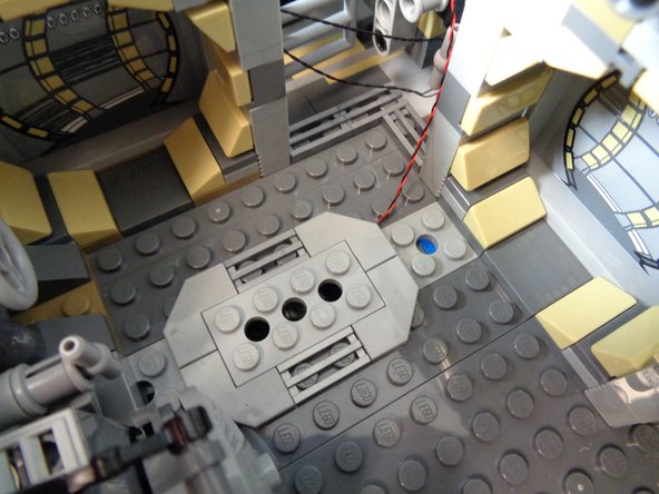
Take another cool white Pico LED from the Main Parts bag, and use one sticky square to attach it under the floor hatch in the rear interior of the Falcon.
-
The photos in this step show one suggested way to mount the light-- you can mount it differently underneath the floor tile if desired.
-
-
-
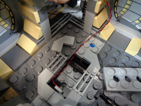
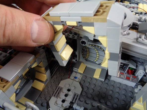
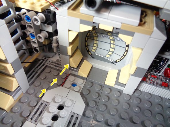
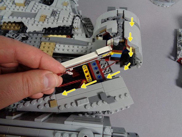
As shown in the first two photos for this step, you can run the wire for the underfloor light along the floor and under the door frame. You can lift the door frame as shown in the first photo if needed to make sure the wire passes underneath.
-
Always make sure to run wires between studs, not on top of them. Wires run on top of studs can be damaged when pieces are placed on top of them.
-
As shown by the orange arrow in the third photo, connect the underfloor light to plug #9 on the BRANCH09X adapter board.
-
You should now have all plugs on the BRANCH09X connected except for plugs 2,3, and 4.
-
-
-
You should now have all small light plugs disconnected from the old BRANCH10 adapter board inside your Falcon. Disconnect the black cable connecting the BRANCH10 adapter to the old TRUNK05 controller, and keep these parts for another lighting project.
-
Note that depending on how your original kit was configured, you may have the wire from the BRANCH10 adapter connected to either a 1/2 BRANCH11 adapter or BRANCH18 adapter instead of the TRUNK05. This is ok-- you want to disconnect the wire going to either the TRUNK05, the 1/2 BRANCH11, or the BRANCH18 (depending on your kit setup).
-
As shown by the green circle in the second photo, you should still have the wire from the hyperdrive not connected to any plug. That's ok-- keep that wire disconnected for now. You will re-connect it later.
-
-
-
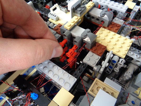
Next, carefully remove the top laser cannon, and carefully disconnect the two plugs as shown by the yellow circles in the second photo.
-
Set the top laser cannon assembly aside for now. You will use it at the end of the installation.
-
-
-
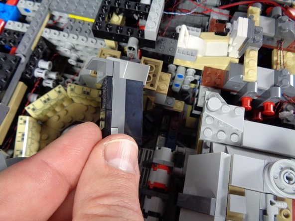
Next, you will disconnect and remove the old cockpit control panel.
-
As shown in the first photo for this step, carefully remove the top panels in front of the boarding ramp, and set aside.
-
As shown in the second photo for this step, the old cockpit panel light should be a single small plug (orange circle) connected to a BRANCH15 adapter board (orange arrow).
-
Carefully disconnect the old cockpit panel light from the BRANCH15 adapter board, and remove the panel assembly from the cockpit as shown in the third photo.
-
-
-
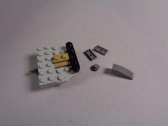
As shown in the first photo for this step, remove the old cockpit control panel assembly and the parts that held it in place.
-
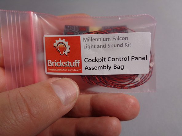
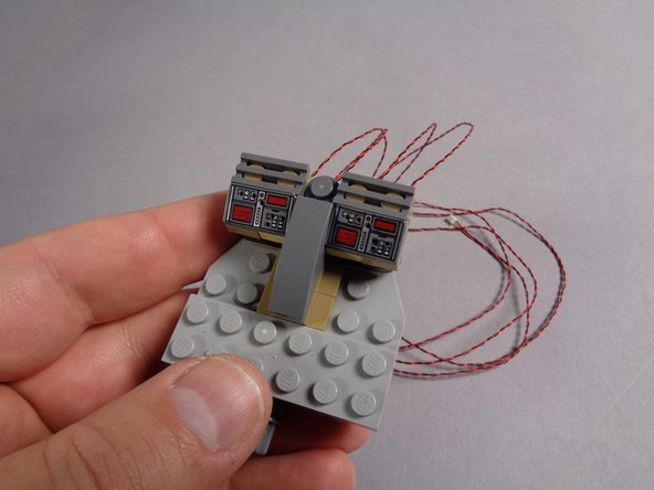
From your upgrade kit, take the small pink bag labeled "Cockpit Control Panel Assembly," remove the new cockpit panel, and attach it as shown in the third photo.
-
The new cockpit assembly has four light wires.
-
-
-
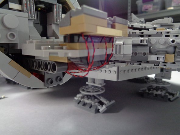
As shown in the first and second photos for this step, re-attach the cockpit control panel section to the Falcon frame.
-
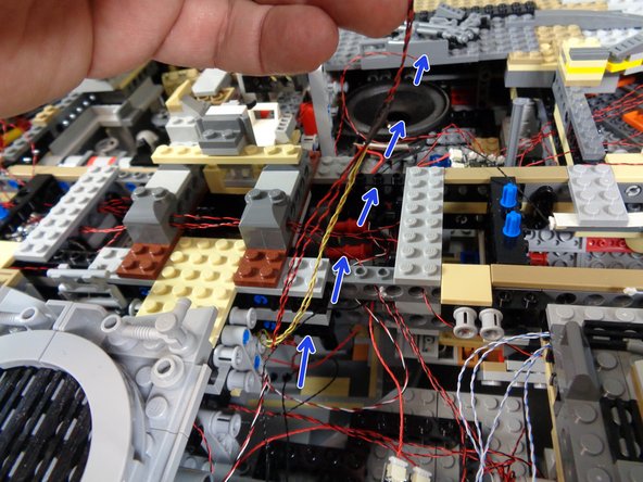
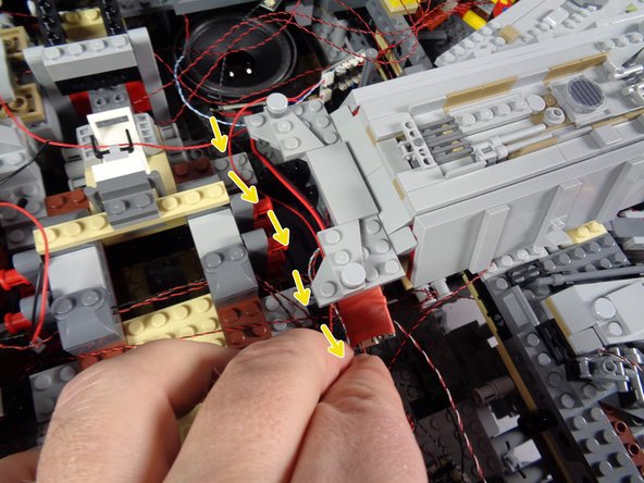
Carefully pass all four light wires under the cockpit floor and back through the hallway section behind the cockpit.
-
As shown by the yellow arrows in the third photo, pass the four cockpit panel light wires through the Technic brick in the Falcon frame.
-
Leave the wires for now. You will connect them soon.
-
-
-
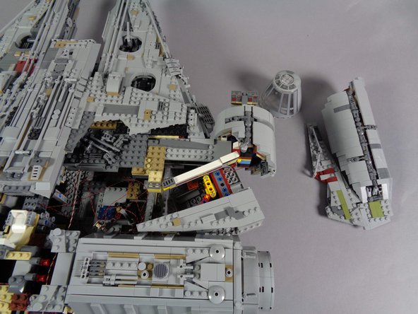
As shown by the orange circles in the first and second photos for this step, position the second BRANCH09X adapter board on top of the front section of the Falcon.
-
As shown in the second photo, carefully remove the top center section of the Falcon (see the green square).
-
As shown by the red square in the third photo, remove the old infrared receiver from the Falcon.
-
Disconnect the old infrared receiver from the old TRUNK05 adapter board, and set aside. You will not need this piece again.
-
-
-
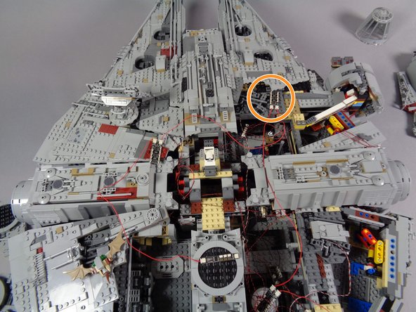
Once you have removed the top center section of the Falcon, find the old BRANCH03 adapter board that connects to the two front mandible lights. See the two green arrows in the first photo for this step.
-
Carefully disconnect the black cable from the large plug on the BRANCH03 adapter board. Leave the two small plugs connected to the BRANCH03 board.
-
From the Main Parts bag, remove another cable with large plug on one end and small plug on the other end (see second photo).
-
As shown by the orange circle in the third photo, connect the large plug of this cable to the large connector on the BRANCH03 adapter board.
-
-
-
As shown by the yellow arrows in the first photo, carefully run the other end of the wire you just connected (the end with the small plug) through the interior Falcon frame, back to the same area as the four cockpit control panel light wires.
-
As shown by the orange arrow in the second photo, connect the small plug of the mandible lights to plug #1 on the second BRANCH09X adapter board.
-
-
-
As shown in the photo, carefully connect the four cockpit control panel light wires to plugs #3,4,5, and 6 on the second BRANCH09X adapter board.
-
As shown by the red "X" in the photo, leave plug #2 disconnected. It is ok not to have anything connected to plug #2.
-
Be careful when inserting plugs-- they will connect in only one direction. Do not force plugs! When inserting, press straight down and not to one side, or the connector can crack.
-
-
-
If you used the extra cool white Pico LED light that came with your old Falcon kit to attach to the interior of the cockpit, disconnect that light from the BRANCH15 adapter board as shown by the yellow circle in the first photo.
-
As shown by the orange arrow in the second photo, carefully connect the plug from the cockpit interior light wire to plug #7 on the second BRANCH09X adapter board.
-
If you did not mount an internal cockpit light when you installed your old Falcon kit, you can skip this step and leave plug #7 empty.
-
-
-
Note that your Falcon kit includes only one laser cannon. You have the option to purchase a second cannon if desired. Please contact us through the contact form on our website if you would like a second cannon.
-
The next section applies only to those who have purchased the lower laser cannon-add on kit. If you do not have this kit, or if you choose not to install the lower laser cannon, you can skip to Step 38.
-
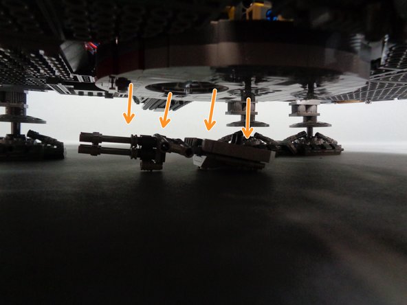
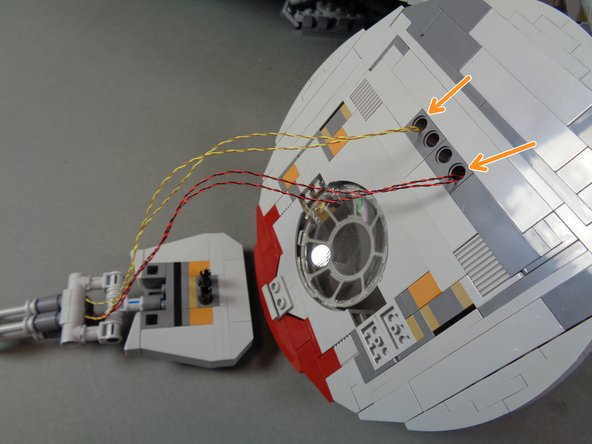
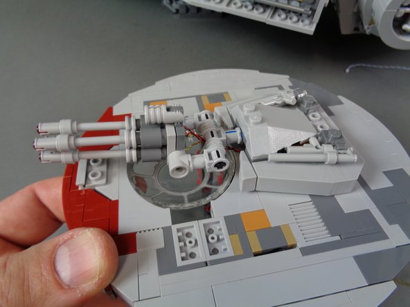
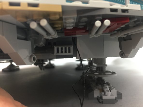
As shown by the orange arrows in the first photo, place your Falcon on a flat surface where you can reach the underside. Gently pull the entire lower laser cannon assembly off the main Falcon frame.
-
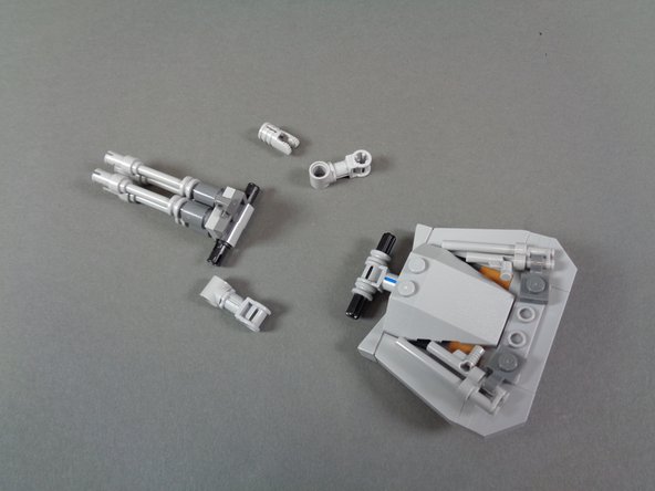
As shown in the second photo, remove the pieces that hold the laser cannon to the turret.
-
Remove the pre-lit laser cannon from its bag as shown in the third photo.
-
-
-
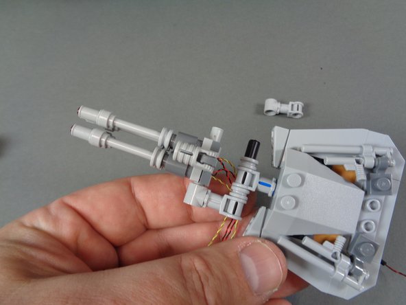
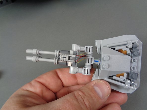
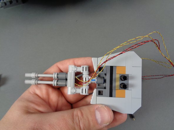
As shown in the photos for this step, mount the pre-lit laser cannon so its wires pass to the lower side of the turret.
-
Your laser cannon may have different color wires, different length wires, or wires of different thicknesses than those shown in these photos.
-
-
-
next you will remove the lower laser mount from the underside of the Falcon.
-
Complete these steps carefully. You may need to gently lift your Falcon to allow removal of the laser mount. It maybe easier to ask someone to help lift your Falcon while you gently remove the mount.
-
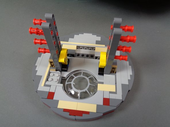
As shown in the first photo, remove the 12 red Technic pins holding the lower mount to the main Falcon frame.
-
Remove the lower mount from under the Falcon.
-
You should now have the complete lower mount removed with red pins attached, as shown in the second photo.
-
As shown by the orange arrows in the third photo, feed the laser light wires through the two OUTER Technic holes in the mount.
-
It is important to run the wires through the OUTER holes, not the INNER holes. The laser cannon itself uses the two INNER holes to attach to the mount.
-
-
-
As shown in the first photo, re-attach the laser cannon to the main mount, being careful to pull the laser light wires (red circles) through the holes so there is no extra slack sticking out.
-
As shown in the second and third photos, you should now have the laser cannon re-attached to the main mount with the light wires passing through the two outer Technic holes in the mount.
-
Before re-attaching the laser cannon mount to the main frame, feed the laser light wires up into the main body of the Falcon. Gently pull them as you re-attach the mount so there are no slack wires sticking out once the mount is fully re-attached.
-
-
-
Carefully re-attach the lower mount to the main frame of the Falcon as shown in the first photo. Carefully re-insert each of the 12 red Technic pins to hold the lower mount firmly in place.
-
Make sure no wires are caught under any pins when re-inserting them. If wires are caught, they can become pinched or cut.
-
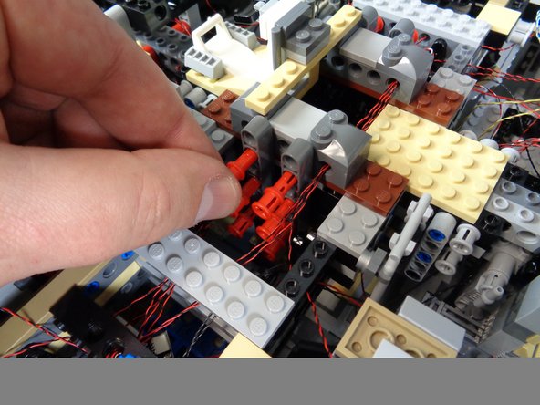
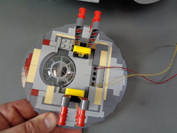
As shown in the second and third photos, pull the laser light wires up through the center of the Falcon and pass the wires through the stud holes in the Technic bricks at the center of the Falcon core.
-
-
-
As shown in the photos for this step, continue routing the laser light wires up toward the second BRANCH09X adapter board.
-
As shown in the third photo, connect the two laser cannon light wires to plugs #8 and #9 on the second BRANCH09X adapter board.
-
It does not matter which wire connects to plug #8 and which connects to plug #9.
-
The BRANCH09X adapter board in the third photo shows a light connected to plug #2. Note that you will not have anything connected to plug #2 (for the upgrade kit, both mandible lights connect to plug #1).
-
Note that you will need to configure your Falcon using the steps found at the end of these instructions, so it recognizes the second laser cannon. Until you apply this configuration change, your lower laser cannon will not be operational.
-
-
-
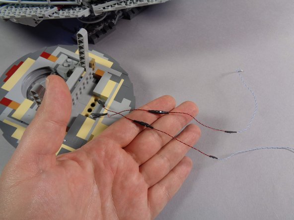
Next you will prepare the new laser sound module for your Falcon.
-
Your old kit will have a different laser sound module, with its speaker likely mounted in the docking bay opposite the boarding ramp. You will no longer be using this sound module or the small lighting effect controller connected to it. You can remove these from your Falcon, or keep them inside.
-
As shown in the first photo, remove the laser sound module and speaker from your upgrade kit box.
-
Carefully remove the speaker from its box, and also remove the laser sound module from its pink bag.
-
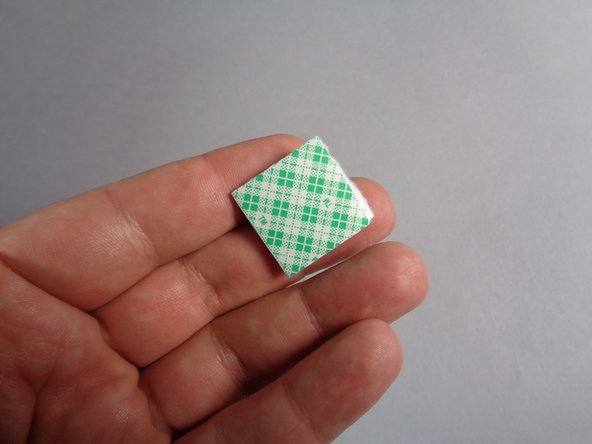
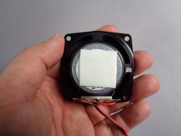
Inside the Main Parts bag, there will be a large double-sided tape square (see the second photo).
-
Carefully remove the covering from both sides of the tape square, and attach it to the back of the speaker as shown in the third photo.
-
-
-
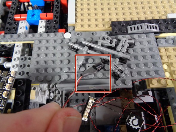
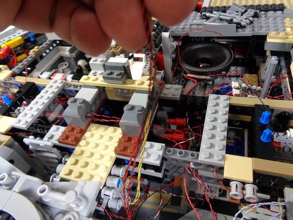
The orange circle in the first photo for this step shows the recommended location to mount the new laser sound speaker.
-
Carefully press down while mounting the speaker so the tape square attaches to the plates underneath.
-
You may need to support the bottom side of your Falcon with your hand in the area just below the speaker as you attach it, to prevent the plate from falling out of the bottom of your Falcon.
-
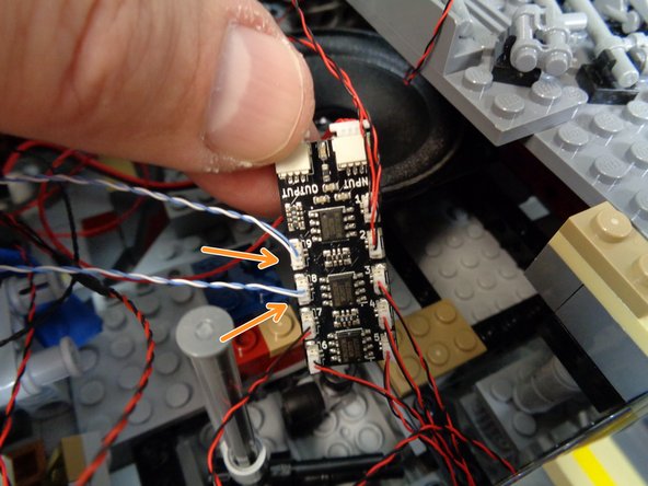
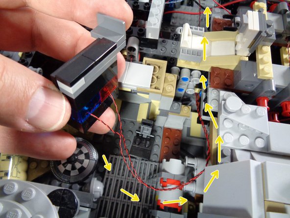
As shown by the yellow arrows in the second photo, carefully pass the thick speaker wires and small sound module (in red shrink wrap) with its two thinner wires behind the boarding ramp, so the thin wires pass back toward the TRUNK08 master controller.
-
If you plan to add custom sounds to the laser module, make sure to keep the microUSB plug on the sound module accessible, so you can connect a USB cable to the plug and download sounds.
-
-
-
If you downloaded your own custom sound files onto the sound module of your old Falcon kit, you will need to move those files onto the new laser sound module for the upgrade kit.
-
Custom sound files were stored on the engines sound module in the old kit, but they have been moved to the laser sound module for the new kit. The engines sound module has a blue shrink wrap covering.
-
Instructions for adding custom sounds to the NEW laser sound module can be found here.
-
Note that the instructions linked above show the laser sound module placed at the back of the Falcon-- this is where that module is mounting the V2 kit from scratch. Because your kit already has the engines speaker mounted in the rear of the Falcon, for the upgrade we recommended placing the laser speaker toward the front.
-
-
-
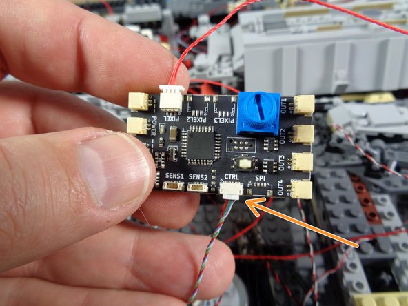
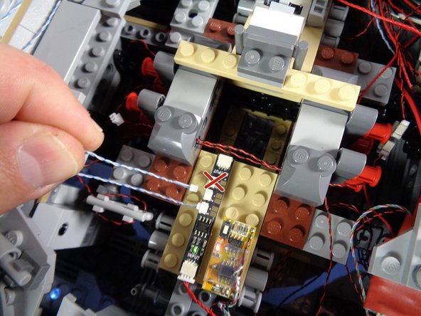
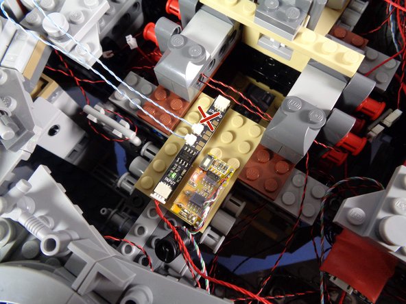
As shown by the orange arrow in the first photo, connect the small 4-wire plug from the laser sound module to the connector on the TRUNK08 master controller labeled "CTRL."
-
Be careful when inserting plugs-- they will connect in only one direction. Do not force plugs! When inserting, press straight in and use your fingernail to press the plug into place.
-
As shown in the second photo for this step, connect the larger plug from the laser sound module to the same adapter board the power plug from your engines sound module is connected to.
-
-
-
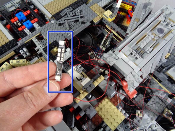
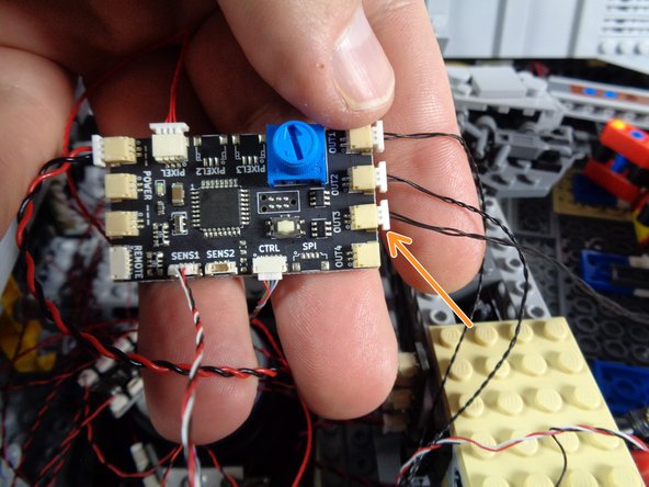
As shown in the first photo for this step, you will now be working with the third BRANCH09X adapter board.
-
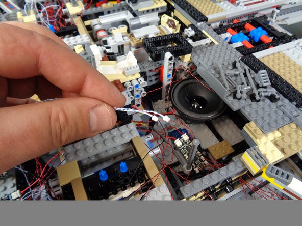
Inside the Main Parts bag, you should have one last cable with a small plug on one end and a large plug on the other, as shown in the second photo.
-
As shown by the orange arrow in the third photo, connect the small plug from this cable to plug #1 on the BRANCH09X adapter board.
-
Be careful when inserting plugs-- they will connect in only one direction. Do not force plugs! When inserting, press straight down and not to one side, or the connector can crack.
-
-
-
You should have one more 2-sided adapter board (2 large plugs) in your Main Parts bag. The adapter will be labeled BRANCH13 on the back.
-
Connect the other end of the cable you just plugged into the BRANCH09X adapter to one of the plugs on this BRANCH13 adapter, as shown in the first photo.
-
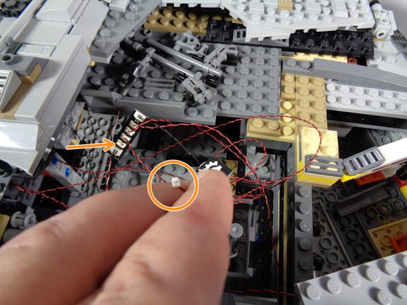
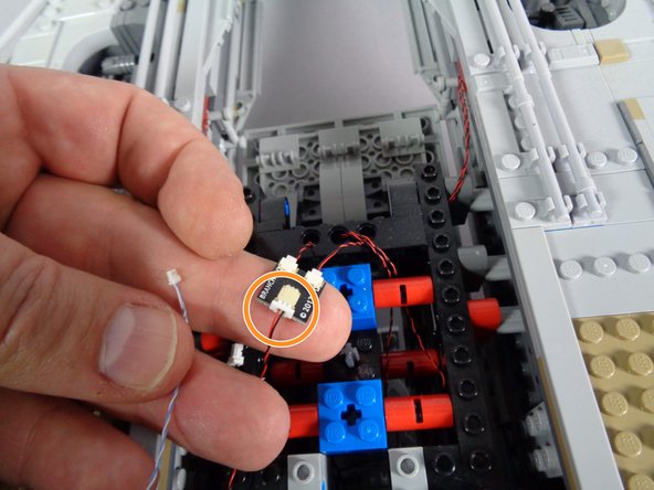
As you did with the first 4-light docking bay LED assembly, locate the single power wire from the 4-light assembly on the Falcon side opposite the boarding ramp. This will be a wire with a large plug, as shown in the second photo.
-
Carefully disconnect the power plug from its adapter, then connect it to the other end of the BRANCH13 adapter board as shown in the third photo.
-
The 4-LED light assembly from the second docking bay should now be connected through the BRANCH13 adapter to plug #1 on the third BRANCH09X adapter board.
-
-
-
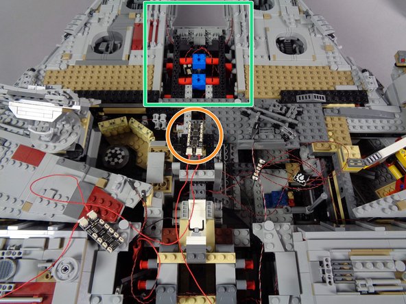
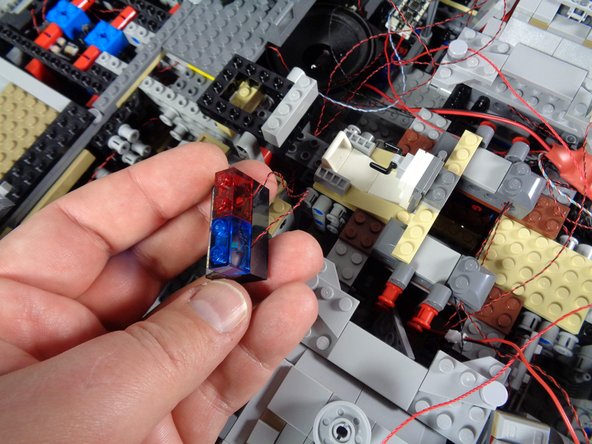
As shown in the first photo for this step, remove the top panel covering the room with the Dejarik (chess) table.
-
As shown in the second and third photos, carefully remove the pieces holding the computer in place.
-
-
-
As shown in the first photo for this step, you should now be able to lift out the entire computer assembly.
-
As shown in the second photo, you should also see a BRANCH03 adapter board and short black connecting cable from the old installation-- you can remove both of these as well.
-
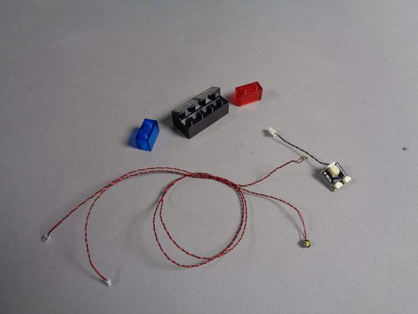
As shown in the third photo, remove the transparent red and blue bricks from the computer panel, then remove the two Pico LEDs from under the bricks. You can use these two Pico LEDs, plus the BRANCH03 adapter and short black cable, for another lighting project.
-
-
-
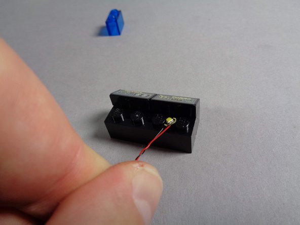
You should have two last cool white Pico LED lights in the Main Parts bag. Remove both of them, and as shown in the first photo for this step, place one of the lights between the studs of the black brick behind the computer panel.
-
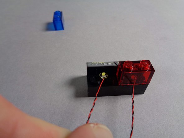
As shown in the second photo, carefully replace the transparent red brick so it covers the Pico LED light, being careful that the light wire passes between, not on top of, the brick's studs.
-
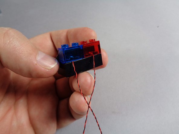
As shown in the second and third photos, repeat this process for the second light and transparent blue brick.
-
Your computer panel should now be re-assembled with two new LED lights mounted under the transparent red and blue bricks. Both LED lights should be in the center of each brick, facing upward.
-
-
-
As shown by the yellow arrows in the first photo for this step, pass the two LED light wires behind the computer and toward the center of the Falcon.
-
As shown in the second and third photos, carefully re-attach the computer, and replace the top frame pieces to hold it in place.
-
-
-
As shown by the two orange arrows, connect the wires for the computer lights to plugs #5 and #6 on the third BRANCH09X adapter board.
-
It does not matter which wire connects to plug #5 and which connects to plug #6.
-
As shown by the three red "X"'s in the photo, you will not have anything connected to plugs #2,3, or 4 of the third BRANCH09X adapter. This is ok.
-
-
-
You should have two remaining interior lights connected to a BRANCH15 adapter board: one for the doorway into the computer room and the other for the light under the Dejarik table.
-
As shown by the yellow circles in the first and second photos, disconnect these two light wires. The arrow in the first photo points to the BRANCH15 adapter board from which you will disconnect the two plugs.
-
As shown by the two orange arrows in the third photo, connect these two wires to plugs #7 and #8 on the third BRANCH09X adapter board.
-
As shown by the red "X" in the third photo, plug #9 on the third BRANCH09X adapter board will be empty. That is ok.
-
At the end of this step, you should have five small plugs connected to the third BRANCH09x adapter board, and four small plugs (2,3,4, and 9) should be open.
-
-
-
You should now be able to disconnect the black wire and BRANCH15 adapter board. You can use these for another lighting project.
-
-
-
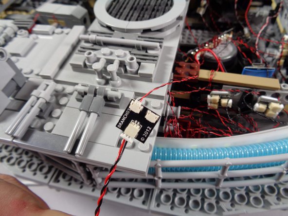
As shown in the first photo for this step, the final adapter board in your chain should be the BRANCH09, which has three small plugs (instead of the nine small plugs on the BRANCH09X).
-
As shown in the second photo, take two small sticky squares from the Main Parts bag and attach them to the back side of the BRANCH09 adapter board.
-
As shown in the third photo, mount the BRANCH09 adapter board to the tan plate just behind the center of the Falcon.
-
Make sure to mount the adapter as shown, with its three small plugs facing toward the left and the INPUT plug (with red cable already connected) facing toward the back of the Falcon.
-
To make attaching the remote control receiver easier, mount the BRANCH09 adapter on the left side of the tan plate, leaving room on the right side.
-
-
-
Your old kit had a small lighting effect module dedicated to controlling the top laser cannon. In your upgrade kit, the BRANCH09 adapter board controls these functions, so you no longer need the old effect controller.
-
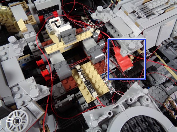
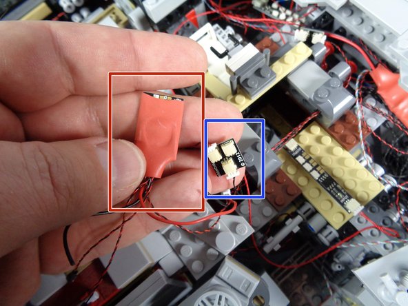
As shown by the red rectangle in the first photo for this step, locate the old laser effect controller-- it will have red shrink covering.
-
Also locate the BRANCH04 adapter board the module is connected to-- this is shown by the blue rectangle in the first photo.
-
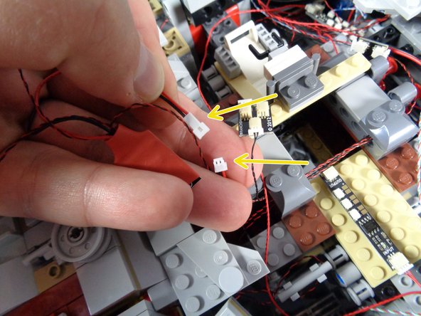
As shown by the yellow arrows in the second photo, disconnect the laser effects controller from the old laser sound module.
-
As mentioned earlier, you may choose to keep the old laser sound module inside your Falcon, or you can remove it.
-
While not shown in the photos, the BRANCH04 adapter should connect back to the old TRUNK05 controller with a black wire. Go ahead and carefully disconnect that black wire from the old TRUNK05 controller.
-
As shown in the third photo, you should now have the old laser effects module, the BRANCH04 adapter, and a black cable. You can use the BRANCH04 adapter and black cable in another lighting project.
-
-
-
As shown by the green rectangles in the first and second photos, carefully disconnect the main power wire from the old TRUNK05 controller.
-
As shown by the yellow arrow in the second photo, connect the power wire to one of the three plugs on the new TRUNK08 controller labeled "POWER."
-
The photo shows the power wire connected to the top plug on the TRUNK08, but you can use any of the three POWER plugs.
-
-
-
Now you will move the control wire for the engines sound module from the old TRUNK05 controller to the new TRUNK08 controller.
-
As shown by the green rectangle in the first photo for this step, disconnect the control wire for the engines sound module from the top right plug on the old TRUNK05 controller.
-
Of the two plugs on the top of the old TRUNK05 controller, the other plug was used for the infrared receiver. You may have already disconnected this earlier when you removed the infrared receiver. If so, that is ok.
-
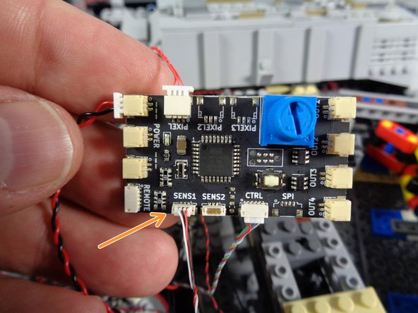
As shown by the orange arrow in the second photo, carefully connect the control wire from the engines sound module to the plug labeled SENSE1 on the new TRUNK08 controller.
-
As explained at the beginning of this guide, if your old TRUNK05 controller says "Version 1.0" on the back side, you will not be able to complete this step, as the wiring for the engines sound module will be different. Please contact us to obtain a special converter adapter at no cost to you, and skip this step until you receive it from us.
-
If your old TRUNK05 controller says "Version 1.2" on the back, you are ok to connect the engines sound module to the new TRUNK08 controller.
-
-
-
As shown by the green rectangle in the first photo for this step, carefully disconnect the black wire from the middle side connector on the old TRUNK05 controller.
-
Be very careful when removing these wires from the connectors on the TRUNK05 controller. The plugs can grip the connectors very tightly, and you can rip out a wire if you pull from the wire to disconnect. Make sure you pull only on the white plug and its tabs. Use a tweezers if necessary to loosen the plug from its socket.
-
As shown by the orange arrow in the second photo, connect the wire you just unplugged from the old TRUNK05 controller to the top plug on the new TRUNK08 controller (labeled OUT1).
-
-
-
As shown by the green rectangle in the first photo for this step, carefully disconnect the black wire from the bottom side connector on the old TRUNK05 controller.
-
Be very careful when removing these wires from the connectors on the TRUNK05 controller. The plugs can grip the connectors very tightly, and you can rip out a wire if you pull from the wire to disconnect. Make sure you pull only on the white plug and its tabs. Use a tweezers if necessary to loosen the plug from its socket.
-
As shown by the orange arrow in the second photo, connect the wire you just unplugged from the old TRUNK05 controller to the second plug on the new TRUNK08 controller (labeled OUT2).
-
-
-
As shown in the first photo, you should now be able to remove the old TRUNK05 controller from your Falcon.
-
There still may be a black wire connected to the top right plug of the TRUNK05 as shown in the first photo-- this is ok. You can use that black wire for another lighting project.
-
The second photo shows the old infrared remote control. You will no longer need this.
-
-
-
As shown in the first photo for this step, locate the small plug that leads to the hyperdrive lights. You disconnected this at the beginning of installing your upgrade kit, but did not re-connect it.
-
Take the BRANCH03 adapter board you used at the beginning of installation to identify the internal lights, and connect the hyperdrive light wire to one of the small plugs on the BRANCH03 adapter as shown by the orange arrow in the second photo.
-
It does not matter which small plug on the BRANCH03 adapter you use for the hyperdrive.
-
You should have some spare black cables after disconnecting and removing lights earlier in the installation. Take one of those spare cables, and connect it to the large plug on the BRANCH03 adapter as shown in the third photo.
-
-
-
As shown by the orange arrow in the photo for this step, connect the other end of the black cable to the plug labeled OUT3 on the TRUNK08 controller.
-
Your hyperdrive should now be connected through the BRANCH03 adapter to the OUT3 plug on the new TRUNK08 controller.
-
-
-
Next you will disconnect the landing lights main power from its old power connection.
-
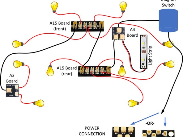
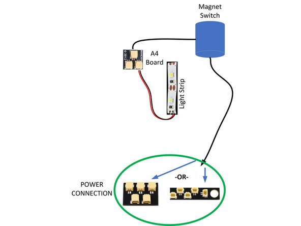
The diagram shows a part of the connections in your old Falcon kit. Specifically:
-
The boarding ramp light strip is connected through the boarding ramp magnetic switch to the main power supply (either a 1/2 BRANCH11 adapter or a BRANCH18 adapter, as shown at the bottom of the diagram).
-
The landing lights are also connected through the magnetic switch of the boarding ramp.
-
This means that, in the old kit, the landing lights were turned on and off by opening or closing the boarding ramp.
-
In the new kit, you need to disconnect the old landing lights power connection, and connect the landing lights to their new connection on the TRUNK08 controller.
-
The next step explains this process in detail.
-
-
-
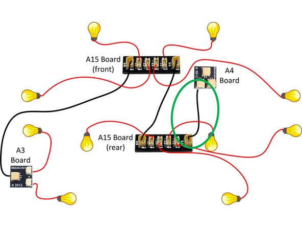
The diagram in this step is the same as in the previous step, but the magnetic switch and boarding ramp light have been removed for clarity.
-
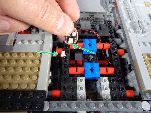
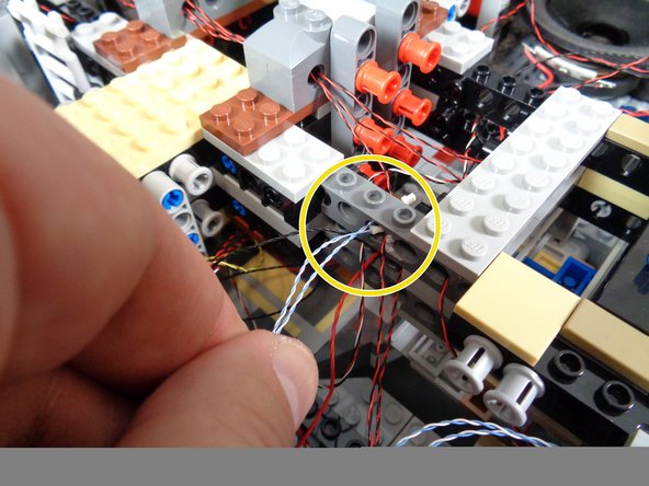
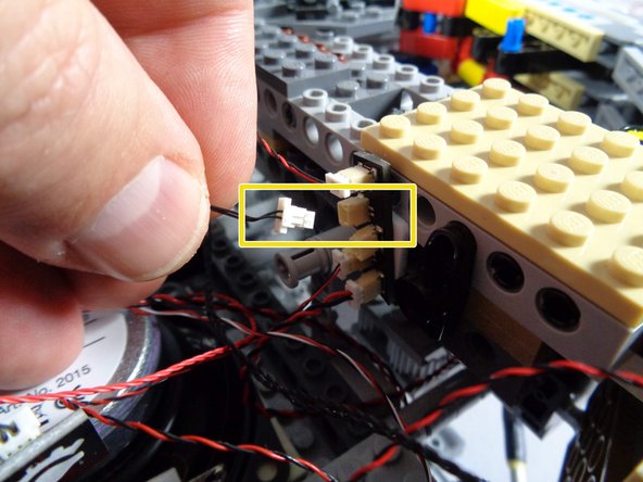
As shown by the green oval in the diagram, you will be looking for a short (1.5"/3.8cm) black connecting cable in the rear of the Falcon, close to where the new TRUNK08 controller board is.
-
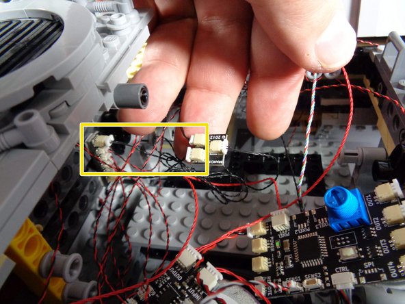
The yellow rectangle in the second photo shows this black wire as it may look inside your Falcon.
-
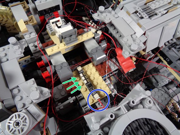
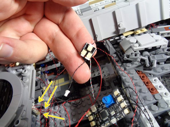
As shown in the third photo, disconnect the short black wire from the BRANCH15 adapter board (shown by the three yellow arrows).
-
Leave all of the other plugs on the BRANCH15 adapter board connected.
-
There are many wires and adapters in this part of the Falcon, so if you need to refer back to the diagram while locating these parts and the short black wire, that's ok.
-
-
-
As shown in the photos for this step, you can disconnect the short black wire from the BRANCH04 adapter board as well.
-
You will not need this short wire, and can use it for another lighting project.
-
Leave the other two wires connected to the BRANCH04 adapter for now. You can place this board back into the body of your Falcon.
-
-
-
As shown in the first photo for this step, you should have at least one spare black connecting cable from the adapter boards you removed earlier in the upgrade installation process.
-
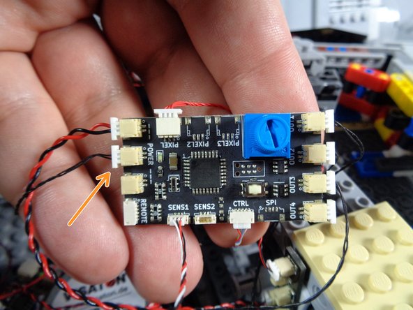
As shown by the orange circle in the second photo, connect one end of that spare black wire to the open plug on the BRANCH15 adapter-- this is the same adapter you just disconnected the short black wire from earlier.
-
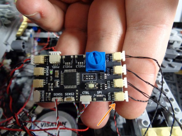
As shown by the orange arrow in the third photo, connect the other end of the spare black wire to the bottom right plug on the new TRUNK08 controller. This plug is labeled OUT4.
-
-
-
The diagram shown in the first photo for this step is a simplified version of the earlier diagram, showing only the remaining power for the boarding ramp magnetic switch and light.
-
Depending when your old Falcon kit was manufactured, you may have the magnetic switch connected to either a 1/2 BRANCH11 adapter or a BRANCH18 adapter-- both are shown in the green circle in the illustration.
-
Inside the rear of your Falcon, look for either the 1/2 BRANCH11 or BRANCH18 adapter (whichever was provided with your old kit), and find the specific plug to which the magnetic switch black cable is connected.
-
As shown by the yellow rectangle in the second photo, carefully disconnect this plug from its adapter (the photo shows a 1/2 BRANCH11 adapter, but you may have a BRANCH18 adapter in your old kit instead).
-
As shown by the orange arrow in the third photo, connect the plug you just disconnected to the second POWER plug on the new TRUNK08 controller.
-
The photo shows the plug connected to the middle POWER plug, but you can use either of the two remaining POWER plugs on the new TRUNK08 controller.
-
-
-
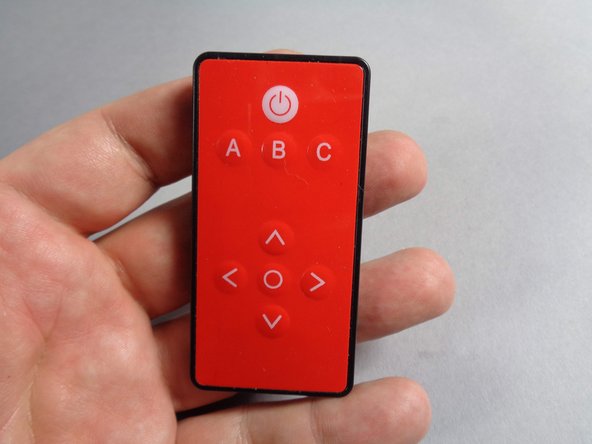
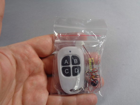
Next you will prepare and install the new radio frequency (RF) remote control that was included with your upgrade kit.
-
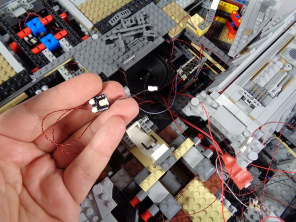
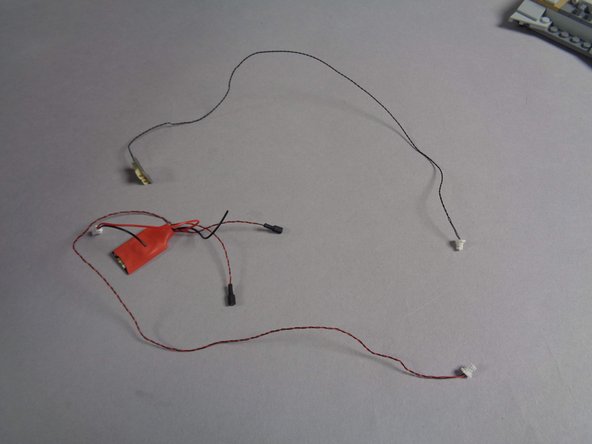
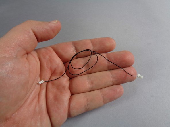
The first photo in this step shows the bag in your upgrade kit containing the 4-button white RF remote and the RF receiver circuit board with antenna (black coiled wire) and other wires attached.
-
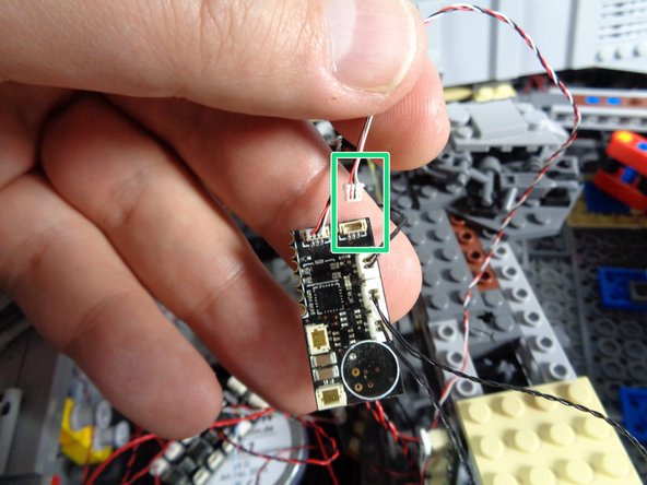
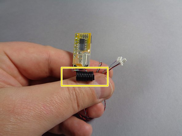
Remove the parts from the remote bag. The second photo shows the RF receiver with its two wires (one for power and the other for control).
-
Do not un-twist or un-coil the black antenna wire on the receiver (the antenna is shown by the yellow rectangle in the second photo).
-
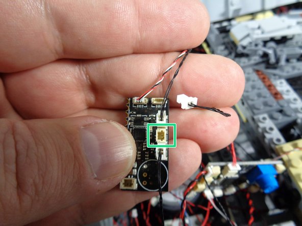
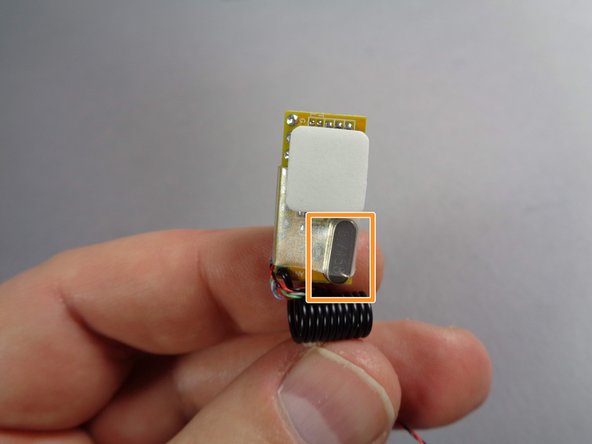
As shown in the third photo, take a large sticky square from the Main Parts bag and stick it to the back side of the receiver circuit board.
-
The back side of the circuit board can be identified by looking for the small silver block shown by the orange rectangle in the third photo.
-
-
-
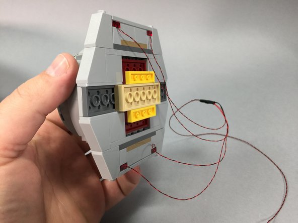
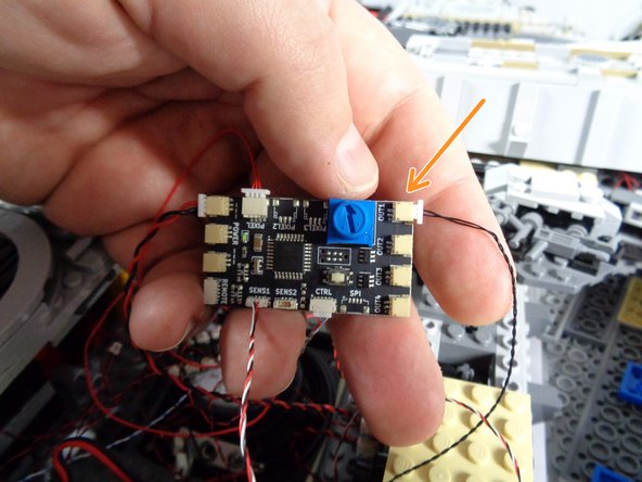
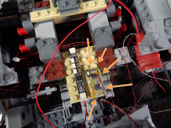
As shown by the orange arrows in the photo for this step, mount the RF remote receiver on the right side of the tan plate, next to the BRANCH09 adapter board you attached earlier.
-
Make sure to mount the receiver with its white button facing toward the center of the Falcon, and the antenna facing toward the back (engines) as shown.
-
-
-
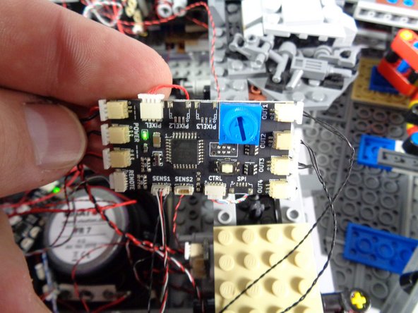
As shown by the orange rectangle in the first photo for this step, connect the larger plug coming from the RF receiver to the last open POWER connector on the new TRUNK08 controller.
-
As shown by the green rectangle in the second photo, connect the smaller plug coming from the RF receiver to the plug on the TRUNK08 controller labeled "REMOTE."
-
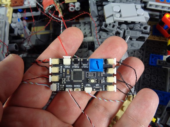
The third photo shows what your new TRUNK08 controller should look like with all wires and plugs connected.
-
The SENS2 plug on the TRUNK08 will be empty at this time. This plug is for the motorized boarding ramp accessory add-on kit, which is available for purchase on our website.
-
-
-
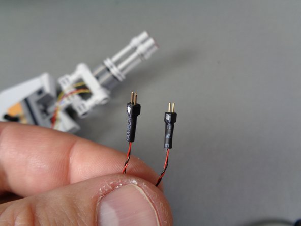
As shown in the first photo, your top laser cannon should have plugs at the end with two gold pins each.
-
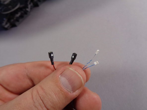
Inside your Main Parts bag in the upgrade kit, there are two conversion cables, as shown in the second photo. These connect to the black plugs of the laser cannon lights and change the connectors so they will fit into the BRANCH09 adapter board.
-
As shown in the third photo, connect the two conversion cables to the laser cannon LED light wires, making sure to match the green, red, or white dots on both sides of each connection.
-
The dots on your plugs may be white, green, red, or another color-- the color of the dots does not matter. The important thing is to make sure the plugs are connected so the dots are on the same side when plugging in.
-
In the rare case that your lasers do not work when the plugs are connected with the dots aligned, try again with the plugs reversed (dots on opposite sides). There is a small chance that the dots on the new plugs may be marked in the opposite polarity. You will not damage your cannon lights by doing this.
-
-
-
As shown in the photos for this step, connect the other ends of the two conversion cables to the bottom two plugs on the BRANCH09 adapter board.
-
These plugs are marked "1" and "2" on the board.
-
As shown by the red "X" in both photos, leave plug #3 on the BRANCH09 adapter board empty. You will not connect any lights to this plug.
-
-
-
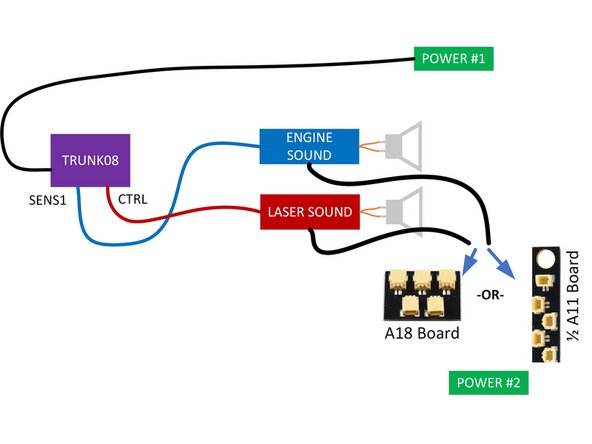
As shown in the diagram for this step, there are two power connections for your Falcon:
-
One connects directly to one of the POWER plugs on the new TRUNK08 controller.
-
The other connects to either a 1/2 BRANCH11 adapter or a BRANCH18 adapter (depending on which you received with your kit). Both sound modules should also have their power connected to this adapter.
-
All other lights in your Falcon should be connected to the new TRUNK08 controller.
-
If you have any spare, unconnected wires or adapter boards inside your Falcon, you can remove them and use them for another lighting project.
-
As shown in the second photo, when you turn on power, the green LED light on the new TRUNK08 controller should turn on.
-
If the green light does not turn on, or if any wires or adapter boards get hot when power is on, disconnect both power sources immediately and contact us for support. This condition is most often caused by a "pinched" wire somewhere in the installation, causing a short circuit.
-
-
-
This step is optional, but can be helpful if you need to extend the reach of your power cables. If you are planning to power your setup using USB battery banks, remember that you will need two. We have some battery bank recommendations here.
-
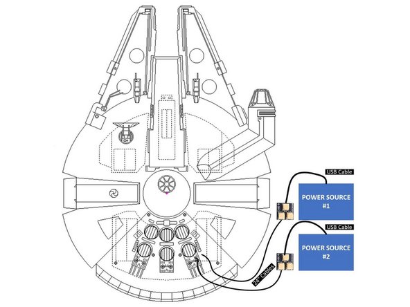
Your kit includes four additional parts you can use to extend power outside the Falcon. You might want to do this, for example, if you have a diorama and you don't want the power wires to be as visible.
-
Included in your kit, there is an Extra Parts Bag. Inside that bag are the four parts you can use to extend your power sources:
-
2x BRANCH04/A4 adapter boards.
-
2x 24"(60.9cm) two-wire connecting cables. The cables included with your kit may be black or red/black, and may be thicker than the wires shown in the photos here. That is ok.
-
The illustration in this step shows how to connect these four parts to extend your power connections.
-
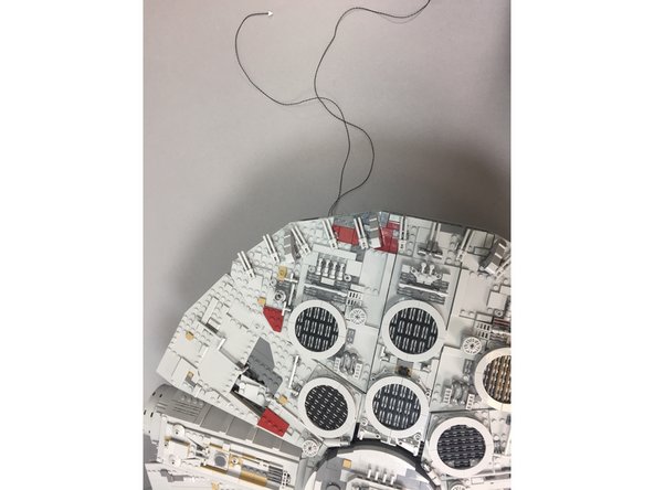
The two photos in this step show the 24" connecting cables extending outside the Falcon.
-
Remember, the color of the wire may be different than the wire shown in the photo-- you may have black wires or red/black wires. Also, your wires may be thicker than the wires shown in the photo. That is ok.
-
-
-
Now it is time to re-attach the top panels on the Falcon, including the tops of the docking bays. Using the LEGO® instructions if necessary to see how to re-attach the panels, carefully re-assemble your ship.
-
-
-
Congratulations! You have finished installing your Brickstuff light and sound kit.
-
To learn how to operate the various functions included with your kit, click here. (this will take you to the "main" installation instructions for the V2 kit)
-
If you have added a second laser cannon, remember that this second cannon will not work until you follow the configuration instructions found in the main installation instructions (click on the link above).
-
To learn how to copy your own custom sounds onto the Falcon's "laser" sound module, click here.
-
THANK YOU very much for your support of our efforts. If you have any questions or problems, you can always e-mail us for help at support(at)brickstuff.com
-
Enjoy your upgraded Falcon!
-


Cancel: I did not complete this guide.
One other person completed this guide.
