Tools
Parts
-
-
There are several ways to read this guide:
-
Reading it on the web in your browser.
-
Downloading a PDF copy of the guide. You can do this by selecting "Download PDF" as shown by the red rectangle in the first photo. Click on the Options heading in the upper right corner of the screen (see the green rectangle).
-
In the "Dozuki" application, which is available for download from the Apple App Store and various Android and Google marketplaces.
-
If you view this guide in the Dozuki app, search for "Brickstuff" the first time you open the app, then select "Product Guides" from the categories listed under Brickstuff. Scroll down to find this guide.
-
You can also translate this guide into another language when viewing on the web. To do this, install a translator extension into your browser and use that extension/plug-in to translate the page. Using the main Google translate website (translate.google.com) does not work.
-
-
-
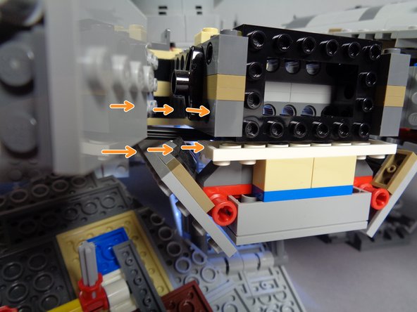
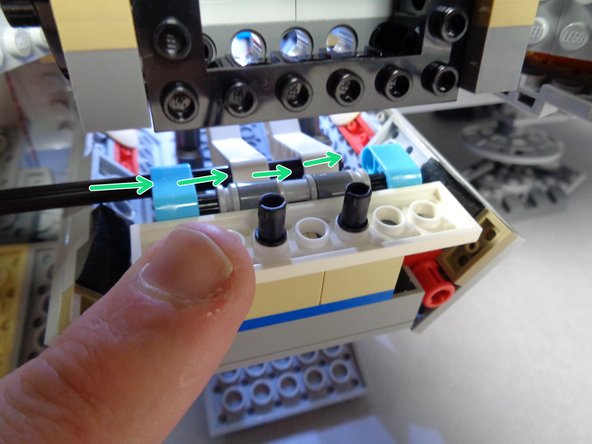
Begin by removing the three large top panels from your Falcon as shown in the first photo.
-
use care when removing the panel above the boarding ramp, as you will have delicate light wires there for the four docking bay lights.
-
As shown by the green arrows in the second photo, remove the two yellow Technic pieces that hold the right rear lower panel onto the main Falcon frame.
-
As shown by the blue arrows in the second photo, let the right rear lower panel hang down once the yellow holding clips are removed.
-
You will likely have one or more landing lights mounted onto this panel, so it can hang down and does not need to be completely removed.
-
-
-
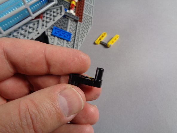
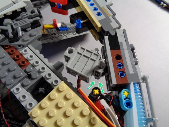
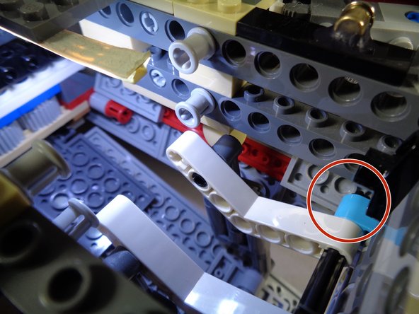
Remove one of the black levers from the Core Parts bag, and attach it to the underside of the Falcon's outer frame as shown in the second and third photos.
-
The red rectangles in the second and third photos show where the lever should be mounted. Make sure it is mounted on the underside of the frame.
-
-
-
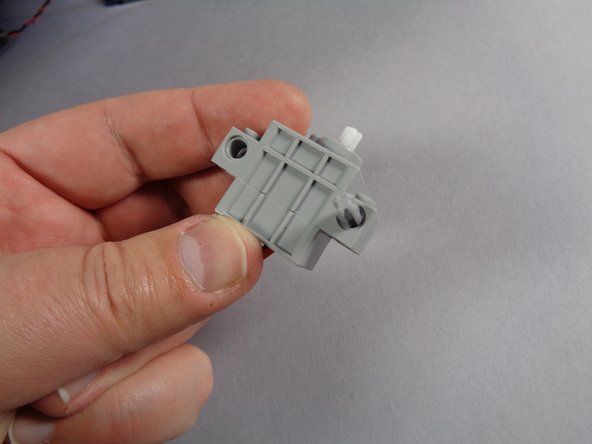
Remove the servo from its bag and also remove the shorter of the light bluish gray Technic axles from the Core Parts bag. This is the 5-stud length axle.
-
As shown in the first photo, pass the axle through the hole in the side of the servo.
-
Make sure to pass the axle through the hole on the side of the servo closest to the white part on the top of the servo.
-
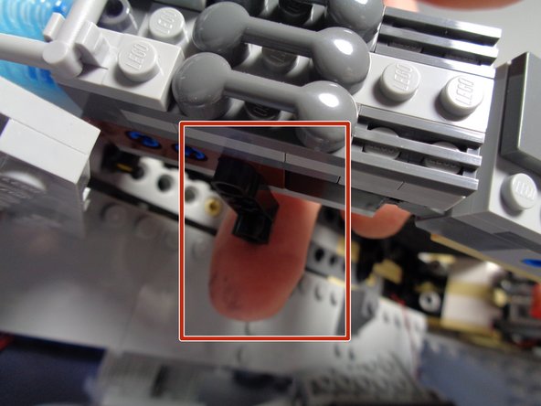
As shown by the green arrows in the second photo, press the end of the axle into the lever you mounted in the previous step. The servo should now be attached to the Falcon frame but should be able to move back and forth on the axle.
-
-
-
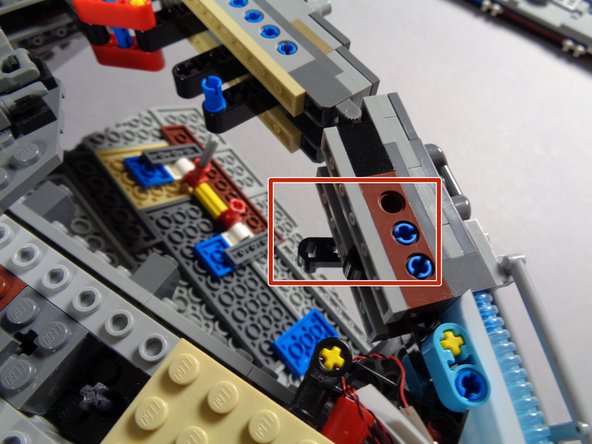
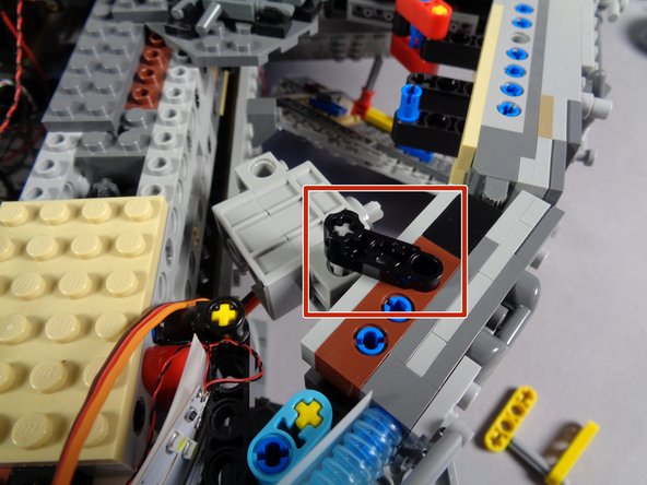
As shown in the photos for this step (and by the red rectangle in the first photo), attach the second black lever to the top of the axle and to the top of the Falcon frame. This should hold the servo firmly in place, yet allow it to rotate slightly.
-
-
-
Next you will prepare the two arms that raise and lower the boarding ramp for modification.
-
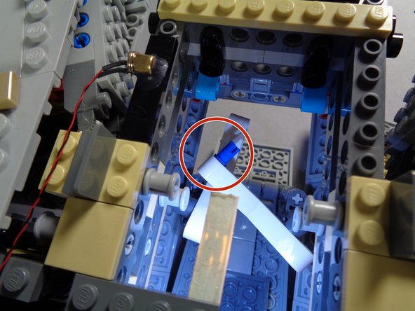
As shown by the red circle in the first photo, remove the first arm from its mount.
-
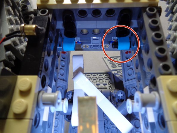
As shown by the green arrows in the second photo, remove the blue Technic pin from the turquoise Technic beam.
-
You may find it easier to remove the pin by using a tweezers or small pliers.
-
When you have finished preparing the first arm, it should look like the third photo, with the arm hanging freely.
-
-
-
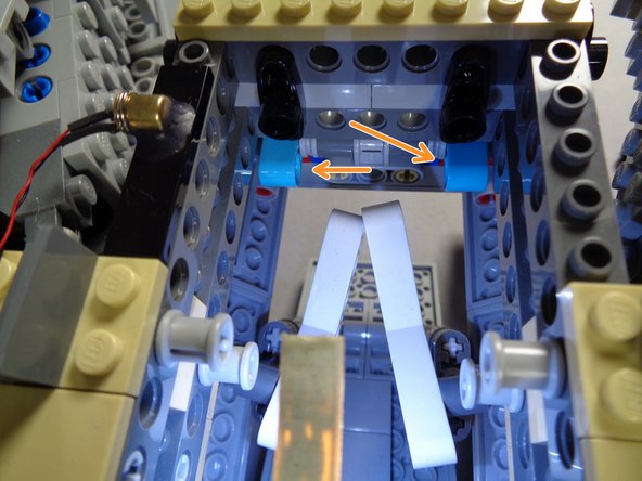
Repeat the same procedure for the other boarding ramp arm as shown in the first photo.
-
When you are finished, both arms and their Technic beams should look like the second photo. Note the two orange arrows showing that both blue Technic pins have been removed.
-
-
-
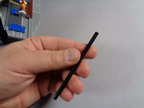
Remove the long black Technic axle from the Core Parts bag as shown in the first photo.
-
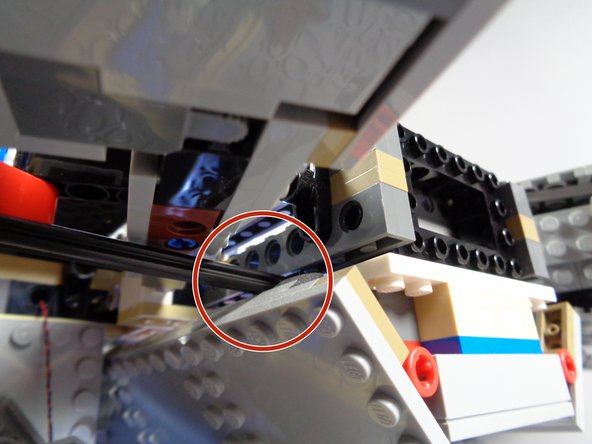
As shown by the red circle in the second photo, carefully pass the black axle through the outer Falcon frame into the boarding ramp area.
-
The orange arrows in the third photo show how the axle should pass into the boarding ramp area.
-
-
-
Make sure your boarding ramp is fully open before completing this step.
-
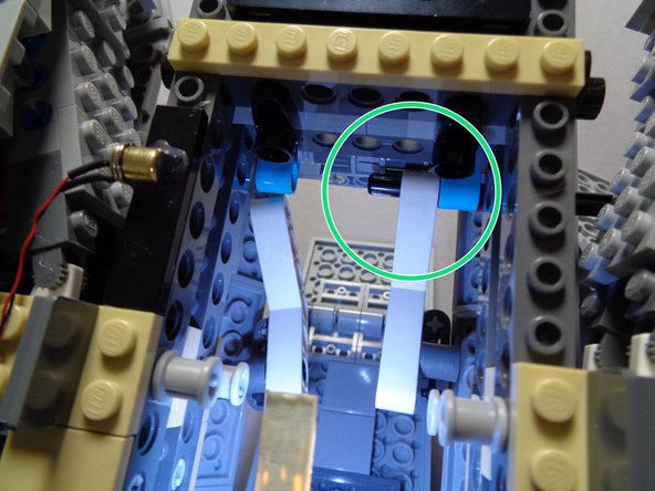
As shown by the red circle in the first photo, pass the black axle through the turquoise Technic beam.
-
As shown by the green circle in the second photo, carefully pass the axle through the first boarding ramp arm.
-
You may need to hold the arm against the turquoise Technic beam while pressing the axle through.
-
-
-
As shown by the red circle in the first photo, continue pushing the black axle through the first ramp arm so it reaches the second arm.
-
As shown by the green circle in the second photo, press the axle through the second arm.
-
Make sure both arms are in the same position (parallel) when inserting the axle into the second arm.
-
The green arrows in the second photo show how the black axle should now be aligned: passing through the first turquoise Technic beam, then through the first ramp arm, then through the second ramp arm.
-
-
-
This is the most critical step in the installation process, and also one of the most difficult. Take your time, and make sure your ramp is correctly aligned before continuing.
-
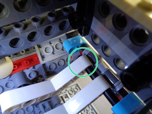
As shown by the red circle in the first photo, press the black axle through the second turquoise Technic beam next to the second ramp arm. The axle should extend a small amount beyond the turquoise Technic beam, but not enough to hit the Falcon frame.
-
This step is difficult because the turquoise Technic beam can easily become detached when you press the black axle through. Move slowly and press on the opposite side of the beam as needed to hold it in place while you fully insert the black axle.
-
As shown by the green lines in the second photo, after you have fully inserted the black axle, you may need to spread out the two ramp arms so they are correctly aligned again.
-
As shown by the two orange circles in the second photo, make sure the arms are positioned so the dark bluish gray Technic beams holding the ramp do not bind against the Falcon frame when manually opening and lowering the ramp.
-
-
-
Before proceeding, you need to make sure the ramp opens and closes freely by turning the black axle with your hand.
-
Try opening and closing the ramp several times by manually turning the black axle.
-
If any of the parts bind or get stuck, you can re-adjust the Technic arms to make sure there is correct spacing on the upper and lower parts, so the ramp opens and closes freely without hitting any of the Falcon frame parts.
-
Do not move to the next step until you are able to freely open and close the boarding ramp by turning the black axle.
-
-
-
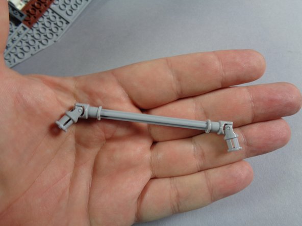
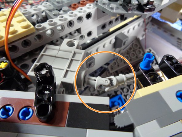
As shown in the photo, take the longer (9-stud length) light bluish gray axle and attach the two light bluish gray universal joints, one on each end of the axle.
-
-
-
As shown by the green arrows in the first photo, the long black axle should be sticking out of the boarding ramp section, toward the rear of the Falcon.
-
As shown by the red circle in the first photo, attach one end of the long light bluish gray axle to the end of the black axle using the universal joint.
-
As shown by the orange circle in the second photo, connect the other end of the light bluish gray axle to the servo using the other universal joint.
-
From this point forward, you will not be able to manually open or close the boarding ramp. If you ever want to go back to manually opening and closing the ramp, you can remove the universal joint at the servo.
-
-
-
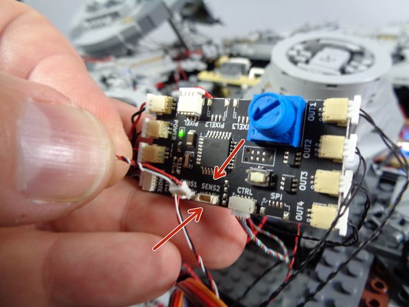
As shown in the first photo, connect the servo wire plug to the "SENS2" connector on your Falcon's TRUNK08 master effect controller.
-
Note: depending on when your kit was made, your TRUNK08 master controller may look different than the one in the photo. This is ok-- all versions of the controller have a "SENS2" connector.
-
Note that the wire will only fit into its plug one way-- do not force the plugs. Press the wire into its plug using your fingernail. When the plug is fully inserted, you will feel a soft "click".
-
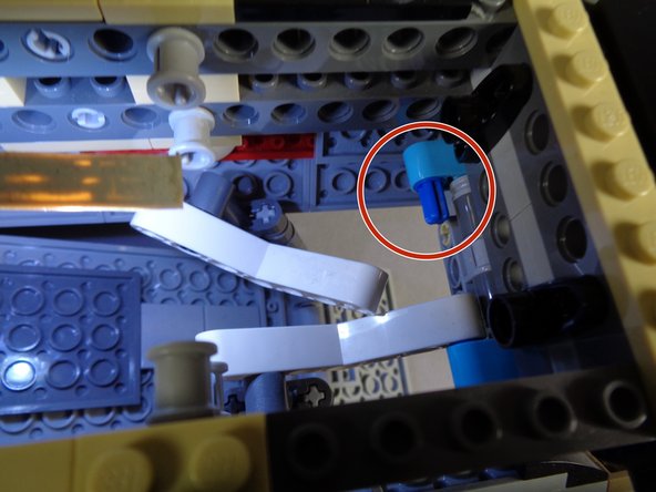
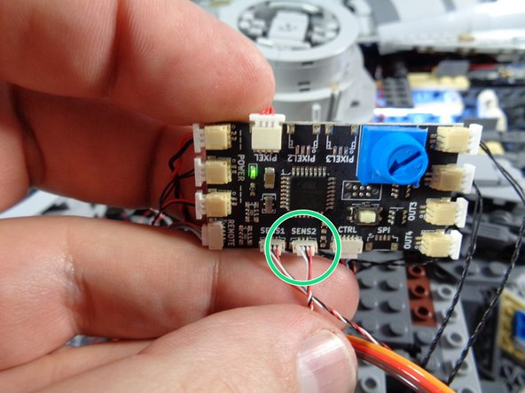
The green circle in the second photo shows the servo wire after connecting to the "SENS2" plug.
-
-
-
In order to operate properly, you need to tell the TRUNK08 master effect controller what the "range of travel" is for the servo. That is, where should the servo stop to indicate a "closed" boarding ramp, and where should it stop to indicate an "open" ramp. To make this setting, follow these steps:
-
Turn off power to your Falcon. As shown in the photo, with the power still turned off, press and hold the white button on the TRUNK08 master effect controller.
-
While still holding the button pressed, turn power back on. Continue pressing the button for 2-3 seconds, then release.
-
Using the blue dial on the TRUNK08 master effect controller, turn slowly until the boarding ramp door is fully open. The servo and ramp should move as you turn the dial.
-
When you have opened the ramp to its fully opened position, press and release the white button.
-
Repeat the same process to tell the TRUNK08 where the "closed" position is. Rotate the dial until the ramp is in the fully closed position (and the boarding ramp light turns off), then press and release the white button.
-
After completing these steps, your Falcon should resume normal operation. You may need to re-adjust the volume, since you used the dial to set the boarding ramp positions.
-
If you move your Falcon or ever need to re-set the open and closed positions on the boarding ramp, you can follow the steps above anytime.
-
-
-
This step and the following two steps show video demonstrations of the servo and boarding ramp in action.
-
To operate the ramp, make sure power to your Falcon is turned on, then activate the ramp with a "long press" (2-3 seconds).
-
As shown in the video, the servo should turn the axles slowly, opening and closing the ramp.
-
-
-
This demo video shows how the ramp's arms operate when moved by the black axle and the servo.
-
-
-
This final demo video shows the rotation of the black axle and the outside walls of the docking bay.
-
-
-
To make more room for the black axle and to ensure that it does not bind while moving, you may remove the two pieces from the lower Falcon panel as shown in the first photo.
-
As shown by the red arrows in the second photo, you can re-attach the extra pieces toward the rear of the panel if you want to keep track of them.
-
-
-
As shown by the green circle in the photo, carefully re-attach the lower panel using the pieces you removed at the beginning of the install process.
-
Before re-attaching the top panels, try opening and closing the boarding ramp using a "long press" of the "D" button on your Falcon's remote. Make sure the black axle is able to move freely, and adjust any internal pieces if needed to make more room for the axle to rotate freely.
-
-
-
Carefully re-attach the top panels of your Falcon.
-
Be especially careful re-attaching the panel on top of the boarding ramp area (shown by the red rectangle in the photo). Make sure not to pinch any wires for the docking bay lights.
-
-
-
Your Millennium Falcon should now have a fully automated boarding ramp.
-
You can control the ramp with a "long press" (2-3 seconds) of the "D" button on your Falcon remote as shown in the video.
-
Note that while the boarding ramp is in motion, any lighting effects running on the Falcon will be paused (this is because of how the servo control works). Once the ramp has finished moving, lighting effects will resume.
-
Note that you cannot open or close the boarding ramp while the Falcon's engines are on. This is to prevent any minifigs from being sucked out into the deep vacuum of space while the Falcon is flying,
-
Thank you very much for purchasing this Brickstuff product! We hope it provides you with increased enjoyment of your Falcon.
-