Introduction
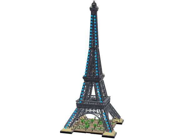
This guide shows how to install the Brickstuff Premium Light Kit for the LEGO Icons Eiffel Tower set (#10307).
Tools
No tools specified.
Parts
-
-
There are several ways to read this guide:
-
Reading it on the web in your browser.
-
Downloading a PDF copy of the guide. You can do this by selecting "Download PDF" as shown by the red rectangle in the first photo. Click on the Options heading in the upper right corner of the screen (see the green rectangle).
-
In the "Dozuki" application, which is available for download from the Apple App Store and various Android and Google marketplaces.
-
If you view this guide in the Dozuki app, search for "Brickstuff" the first time you open the app, then select "Product Guides" from the categories listed under Brickstuff. Scroll down to find this guide.
-
You can also translate this guide into another language when viewing on the web. To do this, install a translator extension into your browser and use that extension/plug-in to translate the page. Using the main Google translate website (translate.google.com) does not work.
-
-
-
The photo for this step shows the main parts included with your Premium light kit.
-
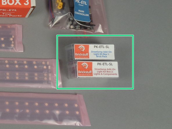
Note that this photo also shows the street lamp add-on kit, which is included in the main box with your other kit parts if you ordered this at the same time as your main kit.
-
The orange box shows the bag of sticky dots and the wire-routing tweezers.
-
The light blue box shows the three small boxes of parts for each section (bottom/middle/top) of your Eiffel Tower.
-
The red box shows the main controller with built-in Wi-Fi.
-
The dark blue box shows the two smaller boxes with the street lamp add-on kit included (for those who purchased this add-on at the same time as the main kit). If you did not order the street lamp add-on, these two boxes will not be present with your kit.
-
The yellow box shows the three bags of color-changing light strips.
-
The purple box shows the USB-C power adapter.
-
-
-
If you purchased the street lamp add-on kit at the same time as your main light kit, your kit will include the two plastic boxes shown by the green rectangle in the photo for this step.
-
You will install these street lamps after you have finished installing the main lights. The installation steps for this add-on kit are covered in a separate manual.
-
-
-
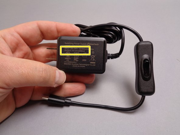
Because of the large number of LED lights included with your Eiffel Tower kit, a special USB-C power adapter is provided. To guarantee proper operation of your lights, you must use only this adapter to power your kit.
-
For our international customers, we apologize that at this time we are only able to provide the power adapter with a U.S.-type power plug. The adapter will work with any mains voltage, so customers needing a different plug type can purchase a simple converter plug. Voltage conversion is not necessary.
-
If you experience any issues with your lights after installation, we cannot provide support unless you are using the power adapter provided with your kit.
-
As shown by the yellow box in the first photo for this step, the power adapter supplies 3 amps (3A) of power at 5 volts DC. This is higher than the standard USB power supply standard, which is why your kit will likely not operate if you use another USB power supply.
-
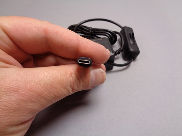
Your light kit also does not support USB-C "Power Delivery" (PD)-type supplies. If you attempt to use a PD supply instead of the supply we have provided, your kit is likely to receive only 500 milliamps (500mA) of power, which is 1/6 the necessary power.
-
-
-
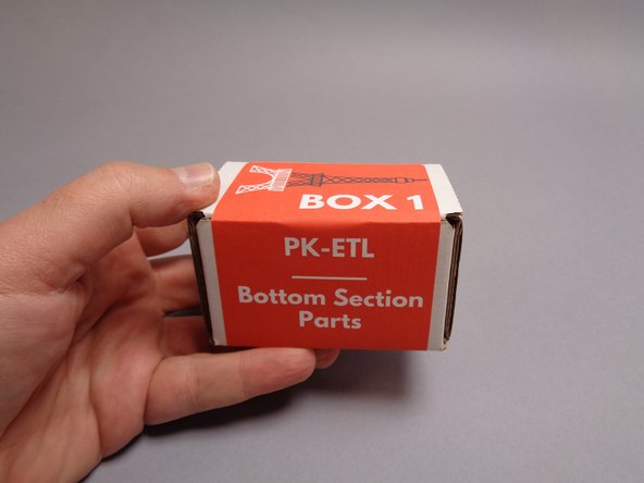
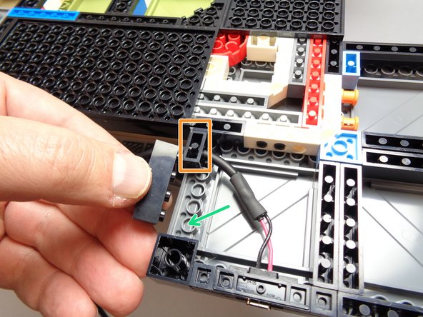
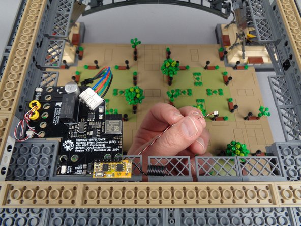
As shown in the first photo for this step, you will begin installation of your light kit with the parts included in Box 1.
-
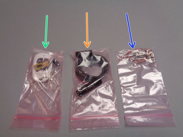
There will be three pink bags inside your Box 1:
-
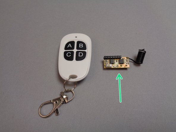
The green arrow in the second photo for this step points to the bag with the handheld remote control transmitter and receiver.
-
The orange arrow points to the bag with the USB-C power connector and its mounting bracket.
-
The blue arrow points to the bag with the connecting parts for the light strips.
-
You will begin installation with the parts in the USB-C power connector bag (orange arrow).
-
-
-
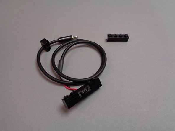
The first photo for this step shows the parts included in the USB-C power connector bag.
-
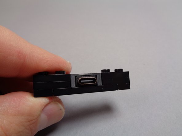
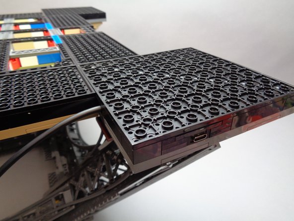
The second photo for this step shows a close-up view of the USB-C power connector bracket, which is made using LEGO parts and a 3D-printed element holding the USB-C plug in place.
-
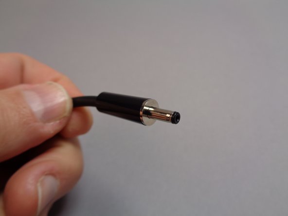
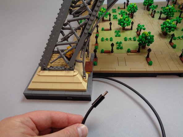
The third photo for this step shows the barrel plug at the other end of the USB-C power connector. This is the plug that connects to the main controller.
-
-
-
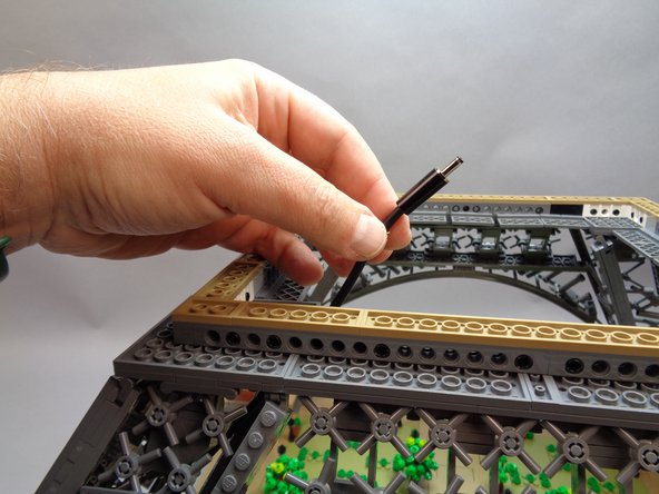
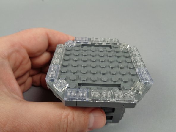
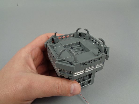
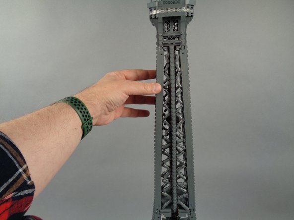
Begin your installation by removing the top sections of your Eiffel Tower and placing the base section on a firm, flat surface with plenty of space around the tower to allow it to be rotated during installation.
-
It is a good idea to have the original LEGO instructions for your Eiffel Tower handy during installation of your light kit. In case any parts come off or if sections of your tower need to be re-built, having the instructions handy will help.
-
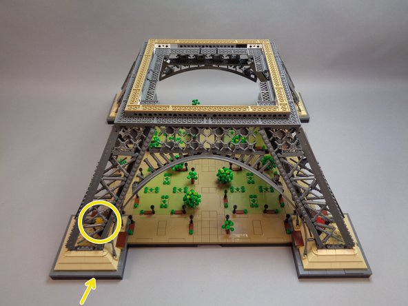
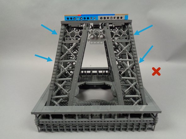
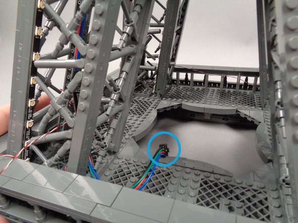
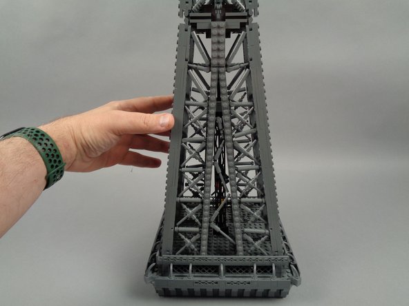
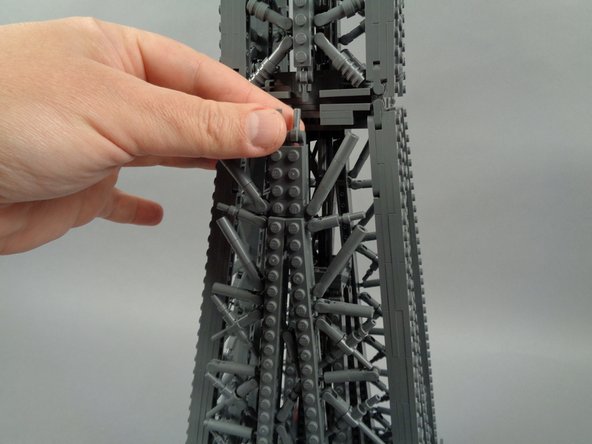
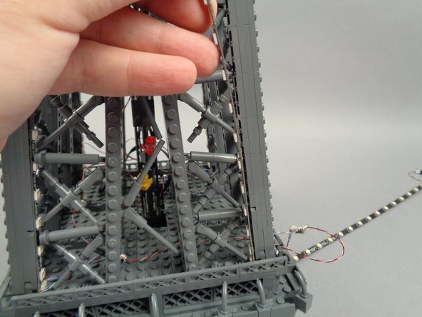
You will pick which "foot" of your Eiffel Tower will be the location where the USB-C power input connector is mounted.
-
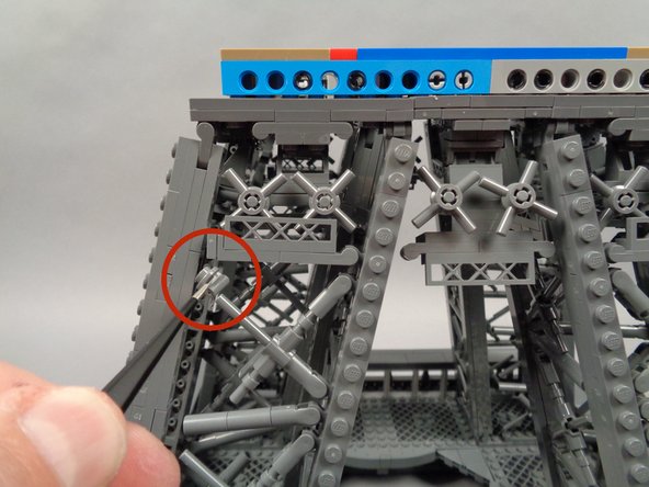
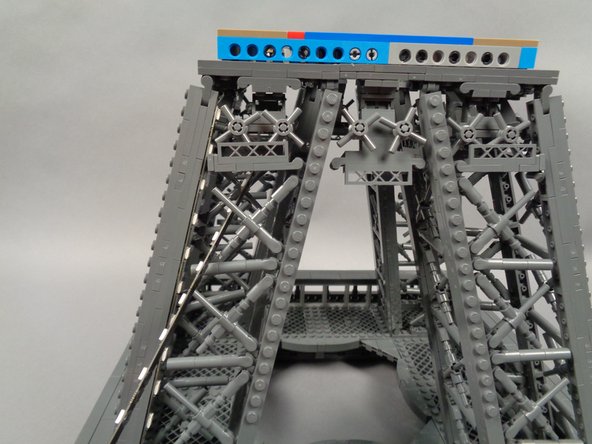
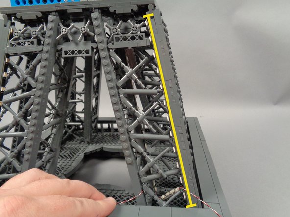
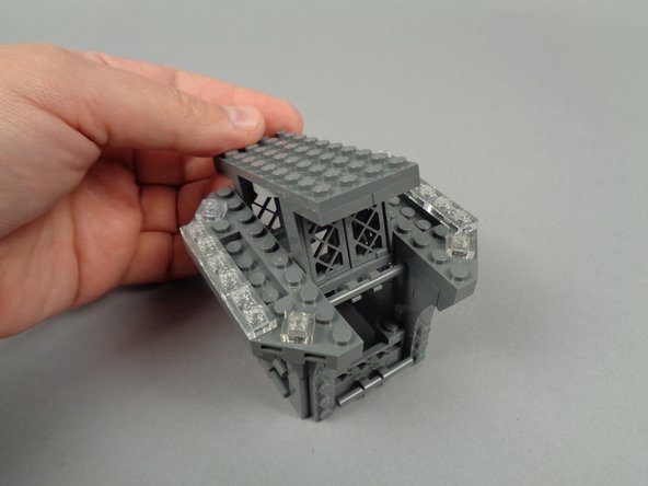
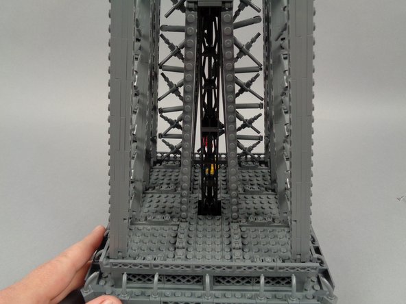
The yellow circle in the first photo for this step shows one of the yellow elevator pieces, indicating we will begin our installation with this "foot" of the tower.
-
The yellow arrow in the first photo shows the location where the USB-C power input connector will be mounted.
-
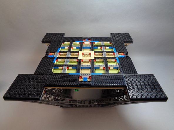
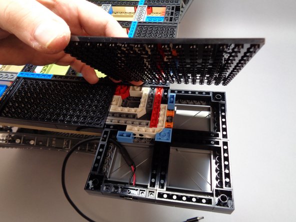
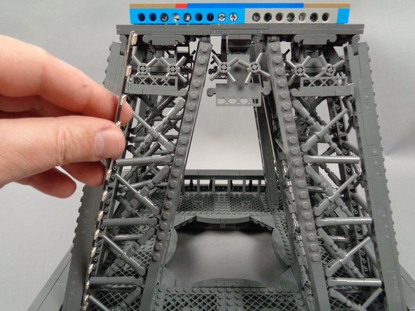
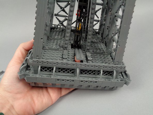
As shown in the second photo for this step, carefully turn over the base of your tower and place it on your work table. The structure should be stable enough to allow the entire assembly to be flipped over without coming apart.
-
If possible, have someone else help support the base as you flip it over.
-
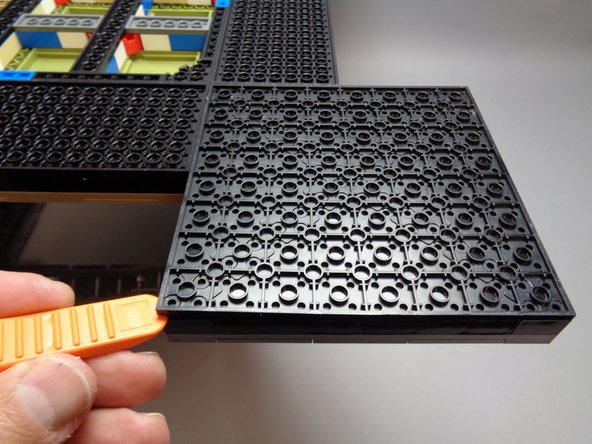
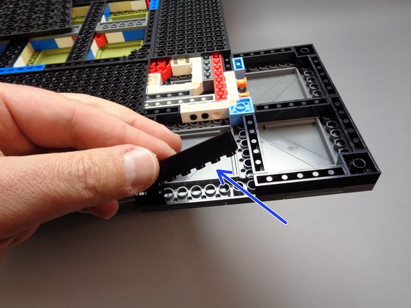
As shown in the third photo for this step, use the LEGO brick separator that came with your set to pry off the large black plate on the bottom of the "foot" where you will mount the USB-C power input connector.
-
-
-
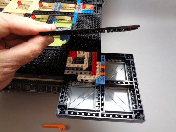
As shown in the first photo for this step, fully remove the large bottom base plate from its foot.
-
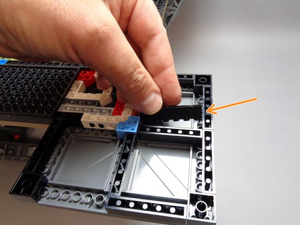
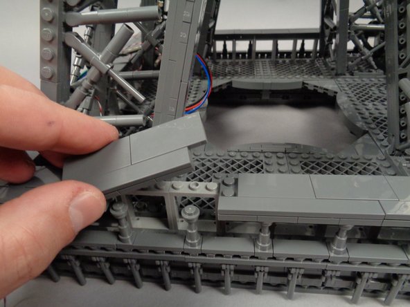
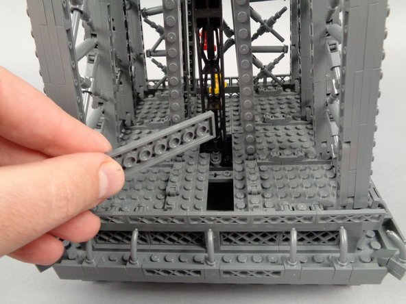
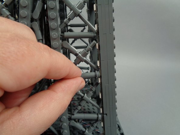
As shown by the blue arrow in the second photo for this step, remove the black 1x6 brick from the front of the foot assembly.
-
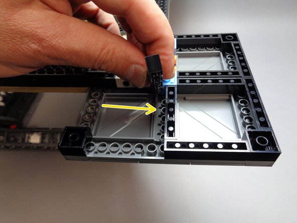
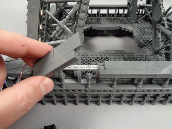
As shown by the orange arrow in the third photo for this step, place the 1x6 brick you just removed in the center of the interior of the foot.
-
When replacing the 1x6 brick, be careful not to press too hard and cause the top side of the tower frame to come loose. It is a good idea to support the top side of the foot with one hand while pressing down on the 1x6 brick with your other hand.
-
-
-
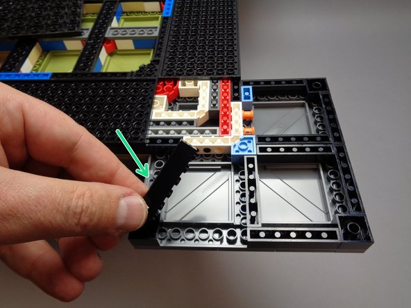
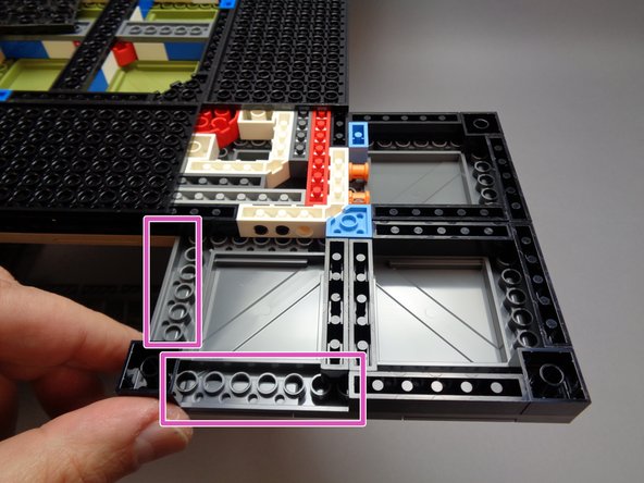
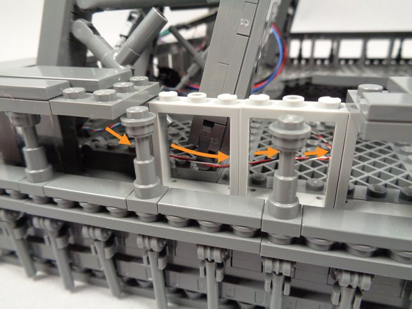
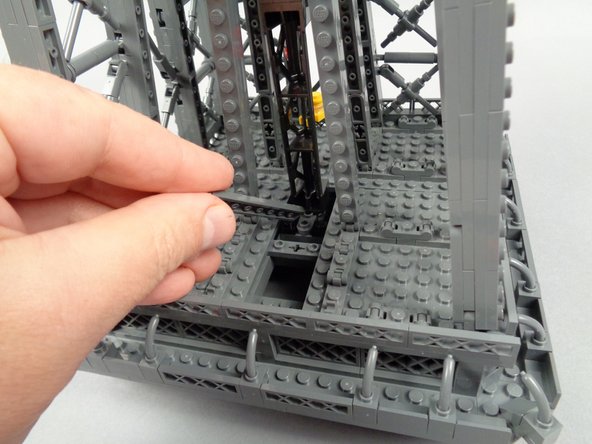
As shown by the green arrow in the first photo for this step, remove another 1x6 black brick, this time from the left side of the foot base.
-
As shown by the yellow arrow in the second photo for this step, place the 1x6 brick you just removed in the center of the foot base.
-
When replacing the 1x6 brick, be careful not to press too hard and cause the top side of the tower frame to come loose. It is a good idea to support the top side of the foot with one hand while pressing down on the 1x6 brick with your other hand.
-
As shown by the two purple rectangles in the third photo, there should now be two 1x6 openings in your base.
-
-
-
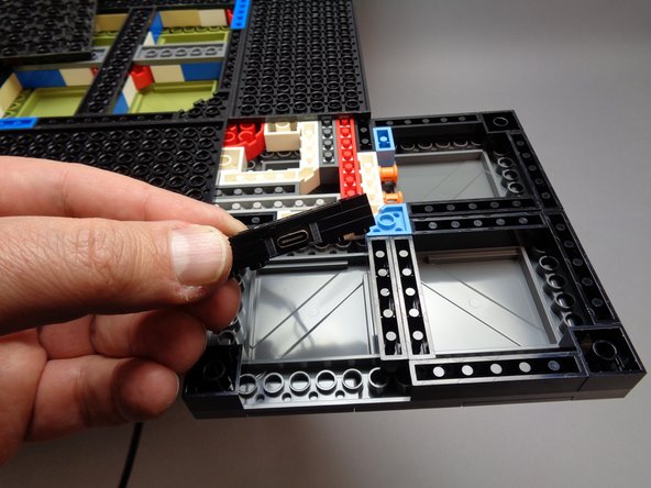
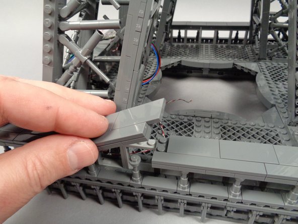
As shown by the photos for this step, insert the 1x6 connector bracket in the area where you removed the first 1x6 black brick.
-
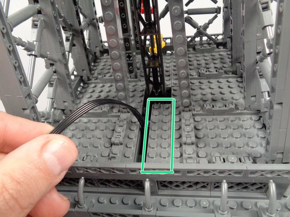
When placing the connector bracket, be careful not to press too hard and cause the top side of the tower frame to come loose. It is a good idea to support the top side of the foot with one hand while pressing down on the bracket with your other hand.
-
-
-
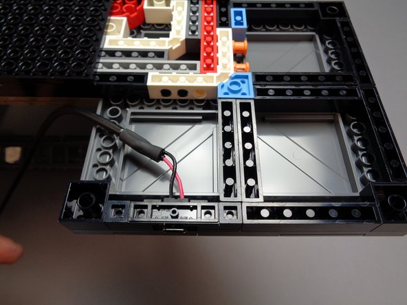
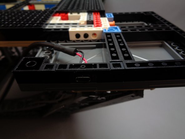
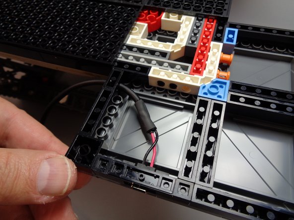
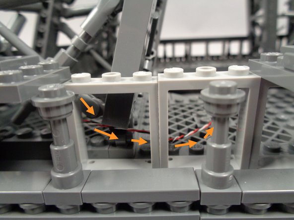
As shown by the orange rectangle in the first photo for this step, attach the 1x2 black brick with hole and power wire at the top of the base opening.
-
As shown by the green arrow in the first photo, take the black 1x4 brick provided with your Brickstuff kit and place it in the gap next to the power cable.
-
The second and third photos for this step show how the power input connector and wire should look when you are done.
-
-
-
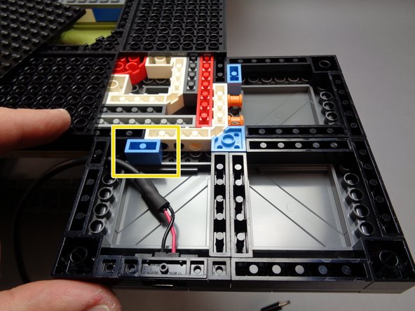
As shown by the yellow rectangle in the first photo for this step, there is a 1x2 blue brick that may have remained attached to the large black base plate when you removed it. You can re-attach this blue brick in the location shown, next to the power wire.
-
As shown in the second and third photos for this step, carefully re-attach the large black base plate to the tower.
-
When replacing the large plate, be careful not to press too hard and cause the top side of the tower frame to come loose. It is a good idea to support the top side of the foot with one hand while pressing down on the plate with your other hand.
-
Make sure all edges of the large base plate are firmly re-attached.
-
-
-
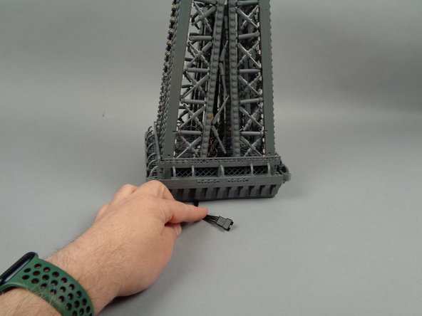
CAREFULLY turn your Eiffel Tower base back to its upright position.
-
If possible, have someone else help support the base as you flip it over.
-
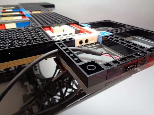
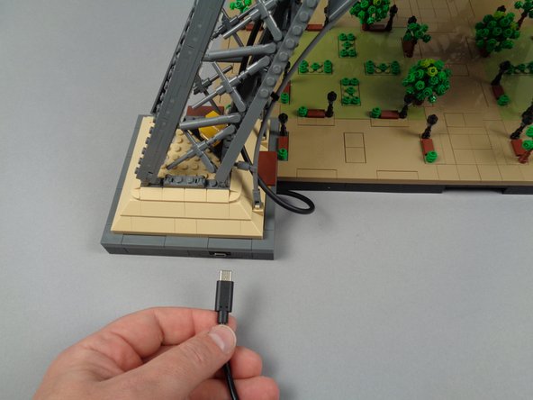
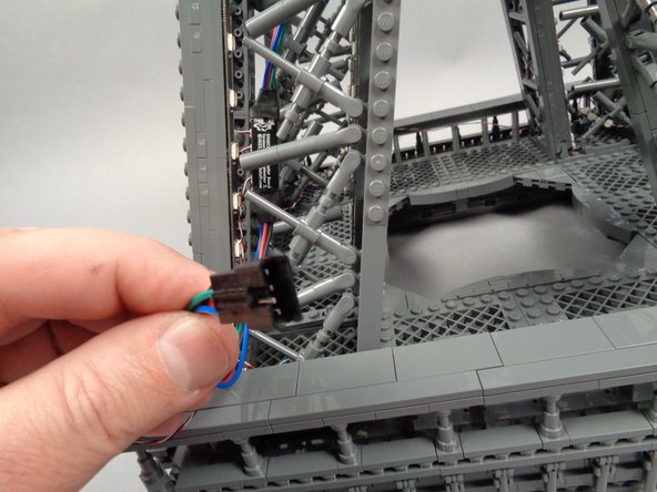
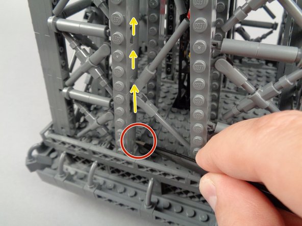
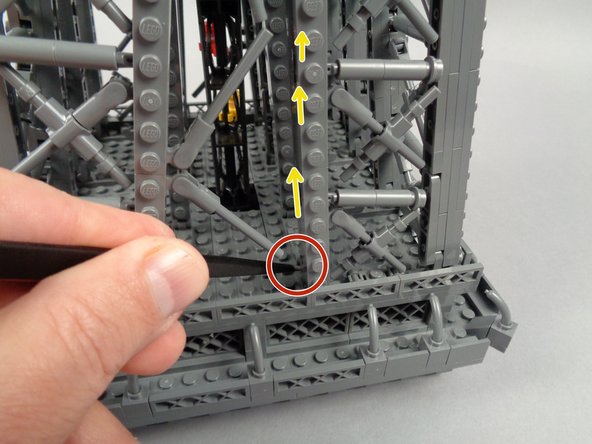
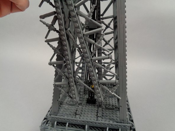
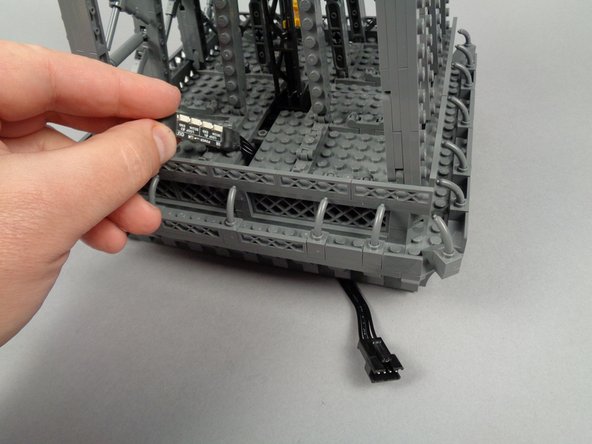
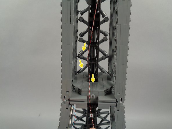
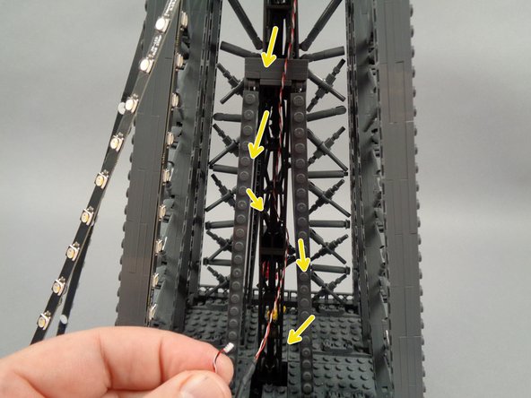
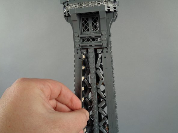
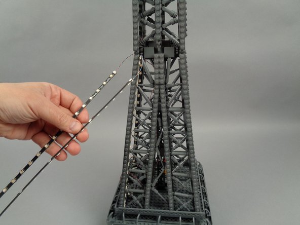
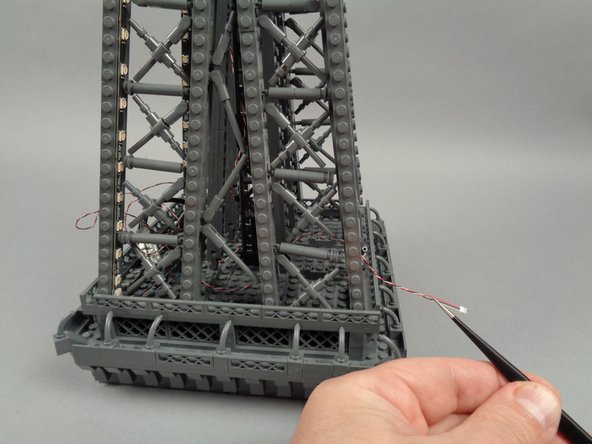
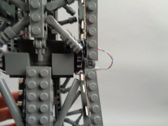
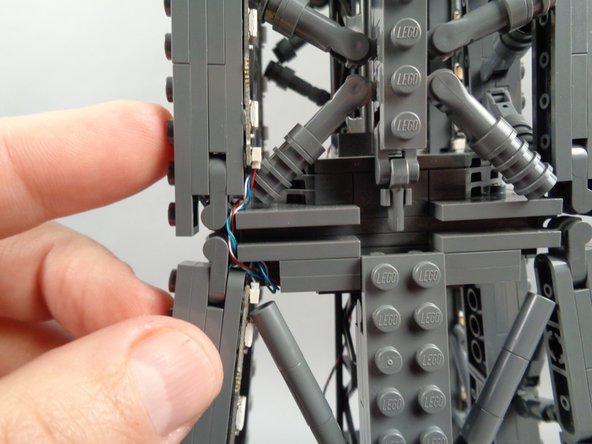
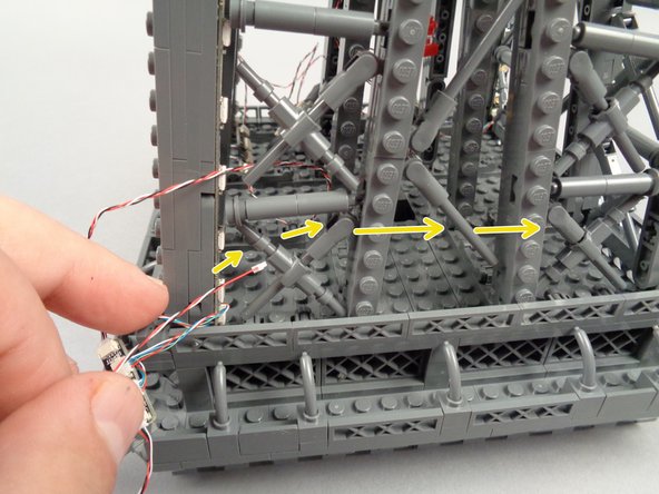
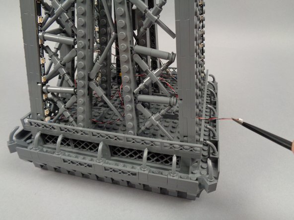
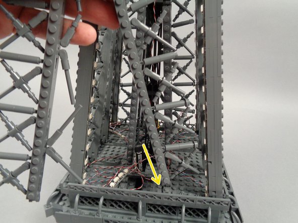
As shown in the first photo for this step, you will now have the power supply cable with barrel connector coming out of the base.
-
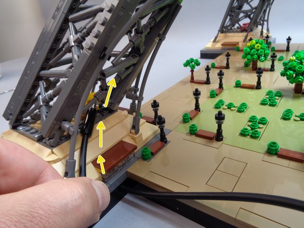
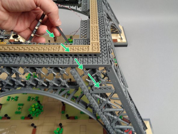
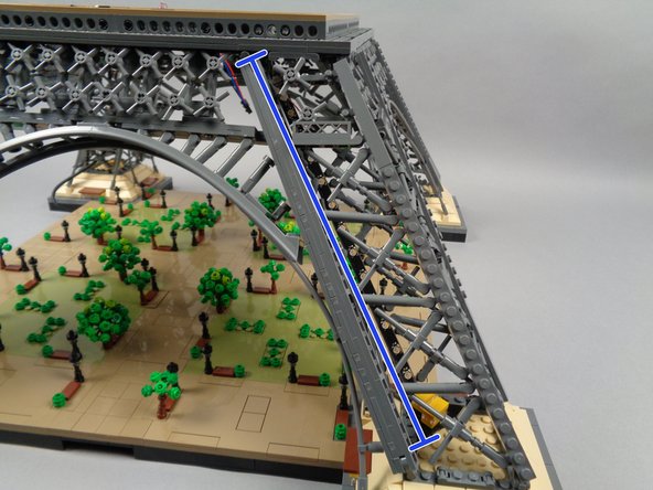
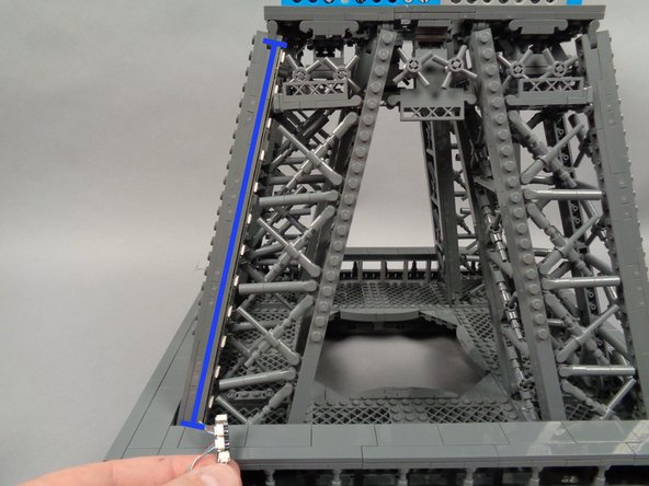
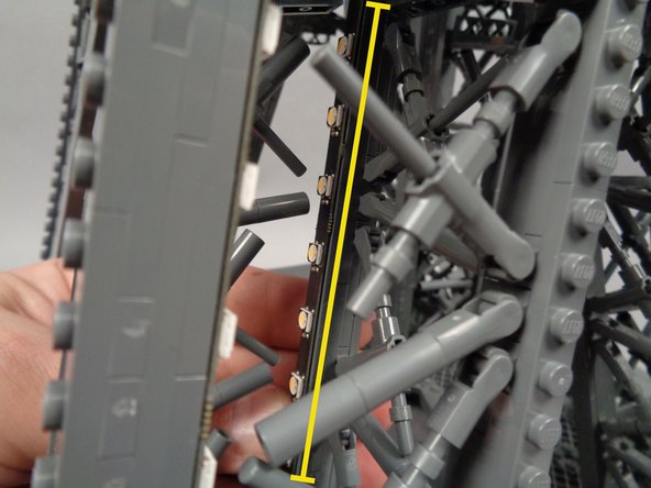
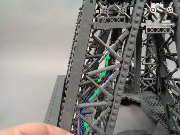
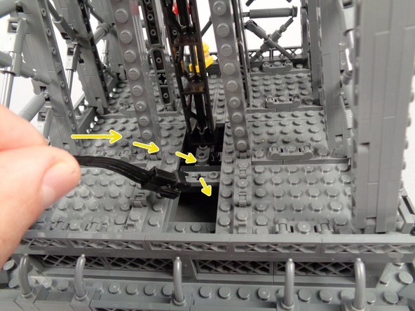
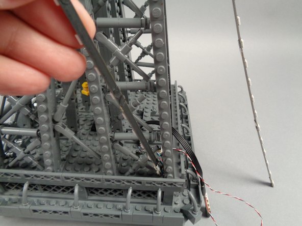
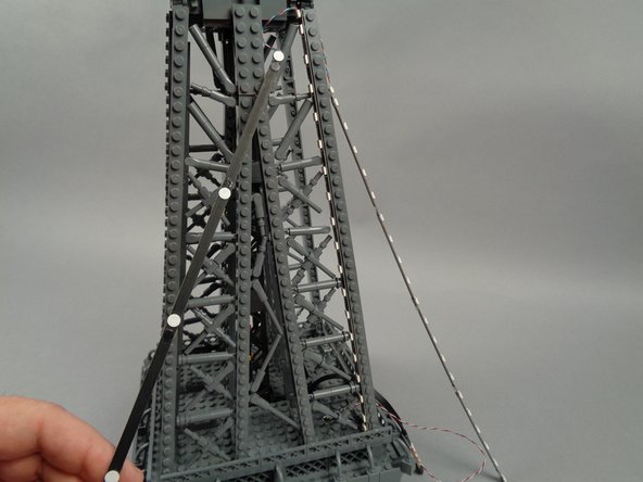
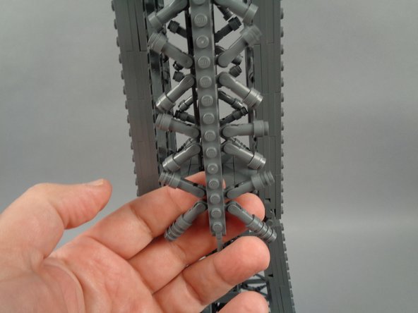
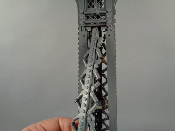
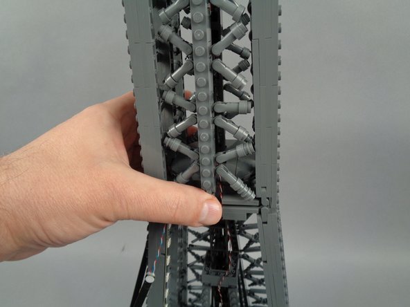
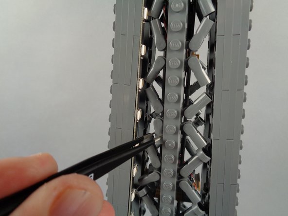
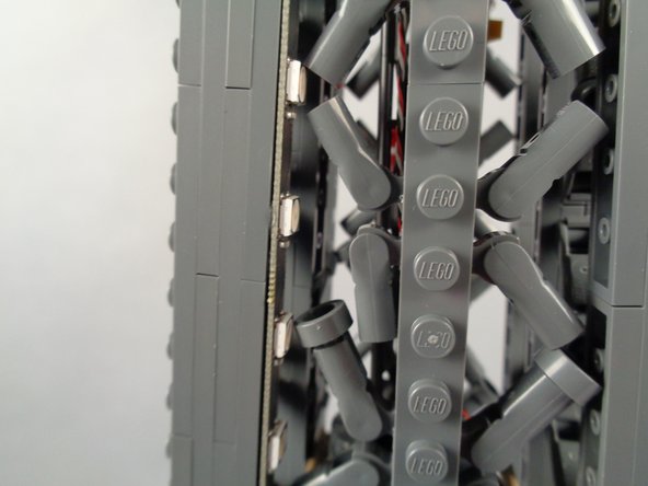
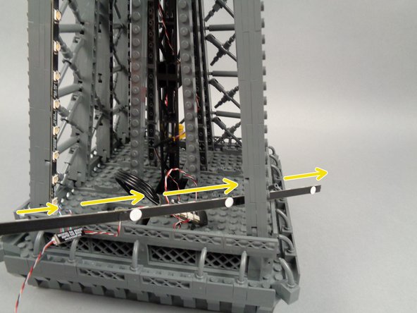
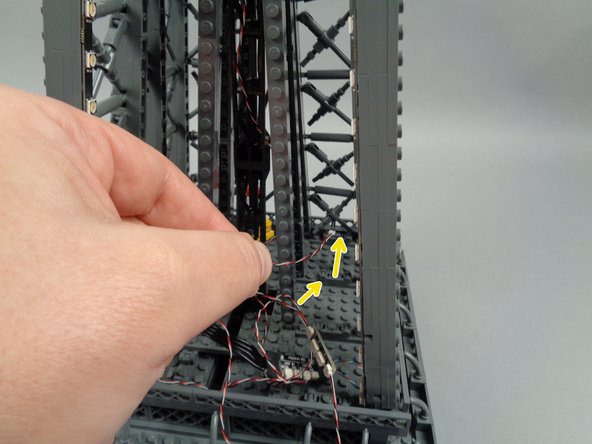
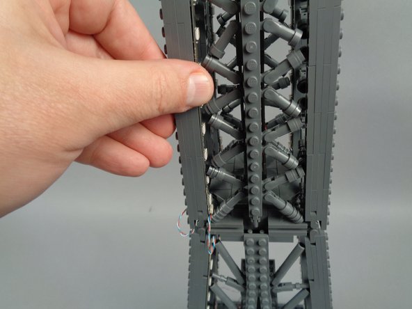
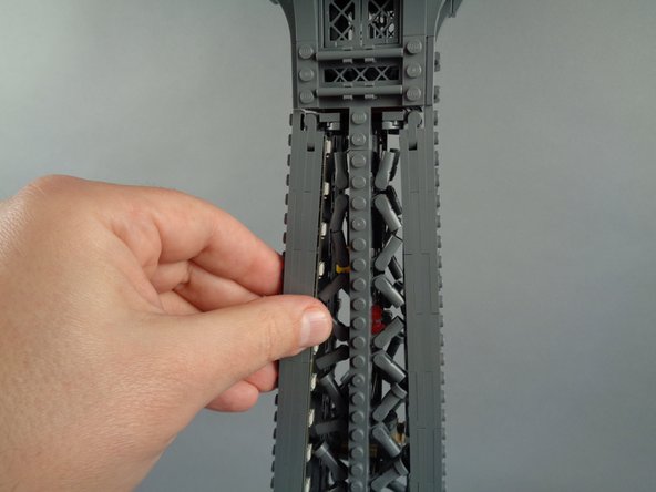
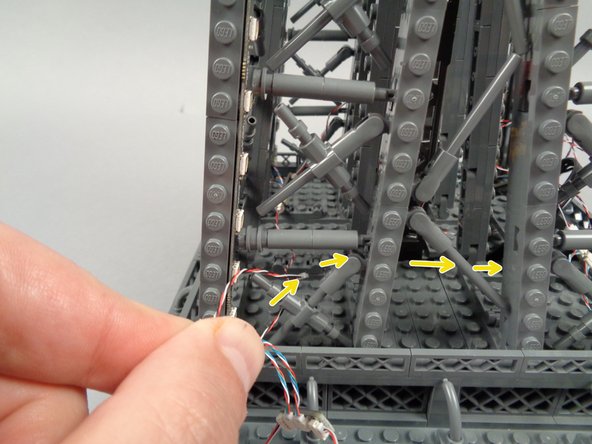
As shown by the yellow arrows in the second photo for this step, carefully pass the power supply cable up through the center of the Eiffel Tower support leg toward the top of the base.
-
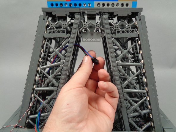
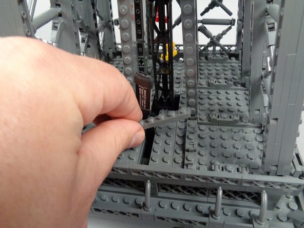
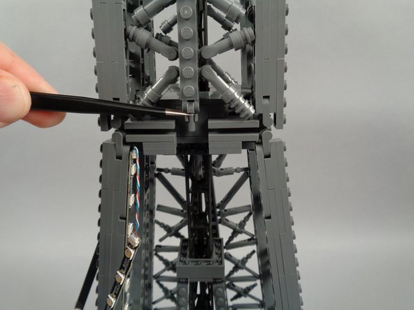
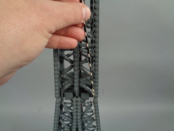
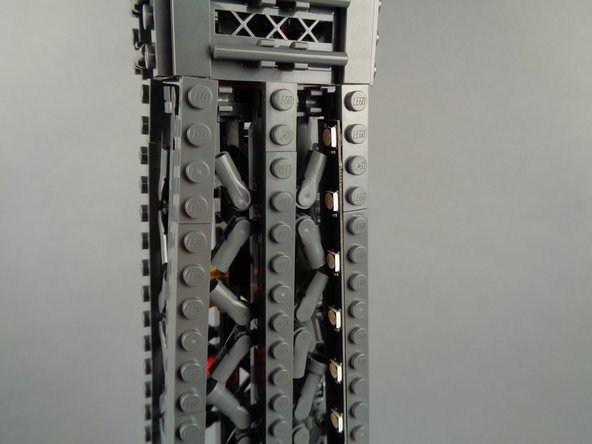
As shown in the third photo for this step, pull the power supply cable out the top of the support leg. Be careful not to pull the cable too hard.
-
If you need help pulling the cable up, you can use the wire-routing tweezers included with your Brickstuff kit to reach inside and pull upward.
-
-
-
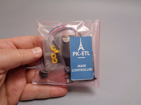
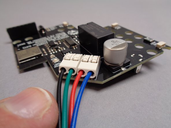
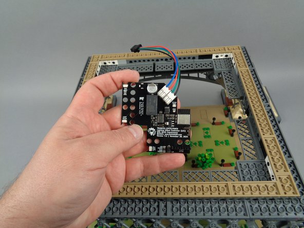
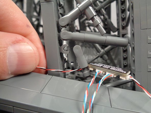
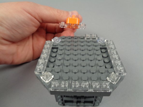
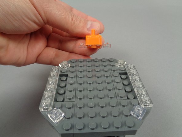
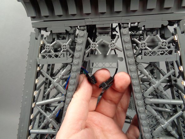
As shown in the first photo for this step, you will now connect the main controller, which is supplied in a large pink bag labeled "MAIN CONTROLLER."
-
Remove the main controller from its bag.
-
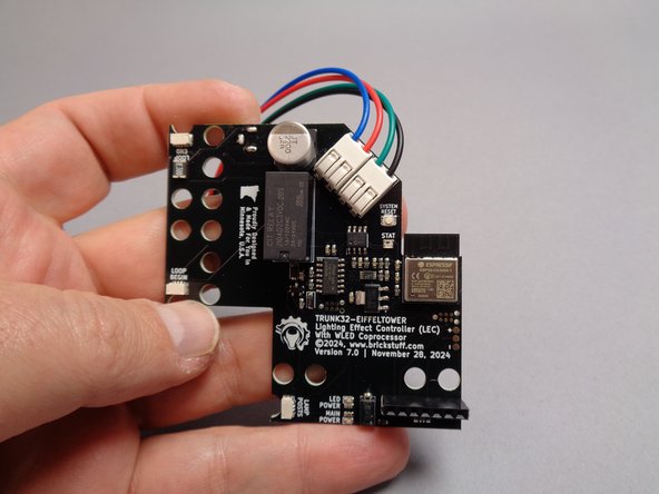
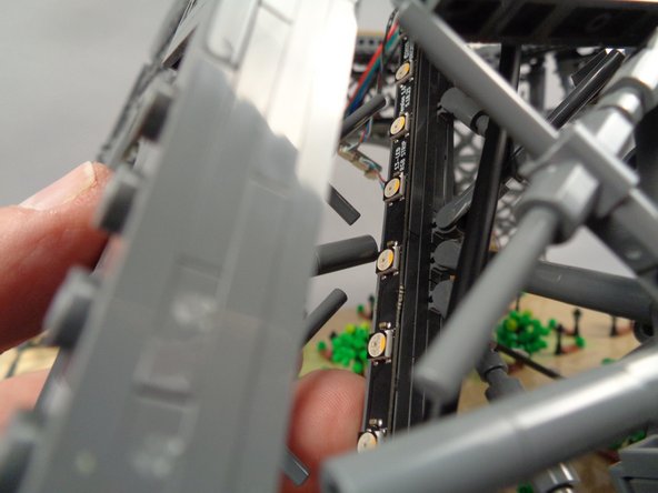
The second photo for this step shows the top of the main controller. Note that four colored wires are attached to the white terminal blocks on the top right edge of the controller board.
-
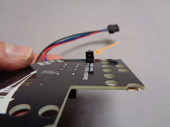
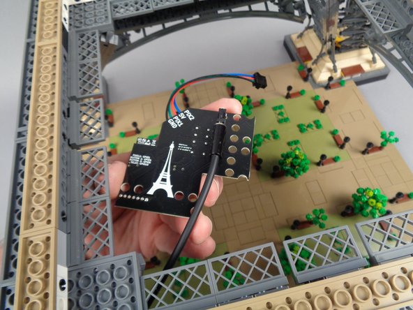
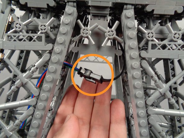
As shown by the orange arrow in the third photo for this step, the main plug for the power supply cable is located on the bottom side of the board.
-
-
-
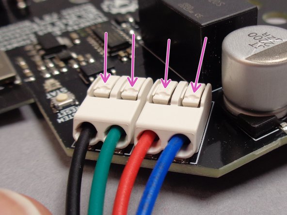
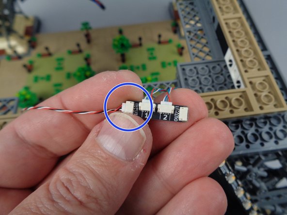
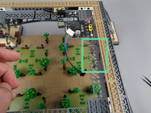
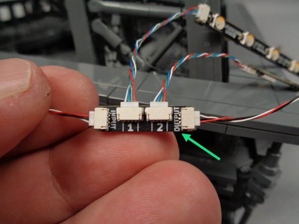
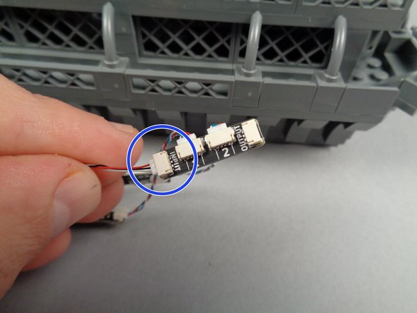
Before proceeding with your installation, check that the four wires connected to the main controller board are firmly inserted into the white terminal blocks, as shown in the first photo for this step.
-
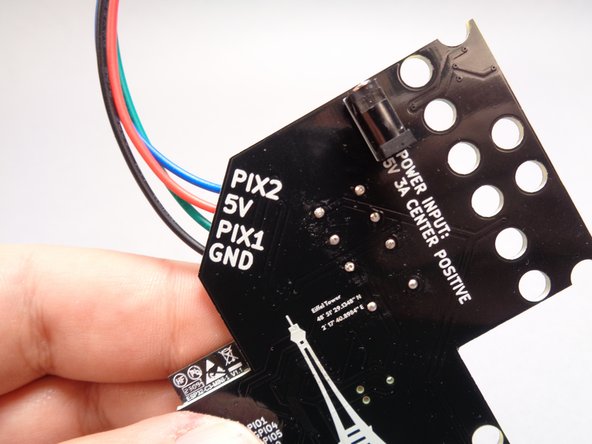
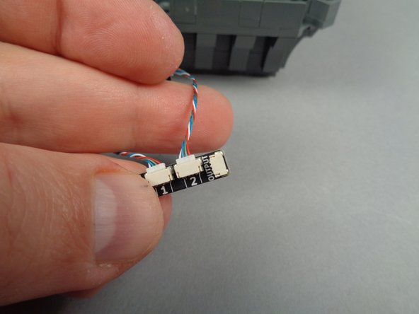
As shown in the second photo for this step, the wires are connected to specific outputs on the main controller.
-
The blue wire is connected to the "PIX2" output.
-
The red wire is connected to the "5V" output.
-
The green wire is connected to the "PIX1" output.
-
The black wire is connected to the "GND" output.
-
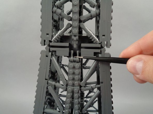
If any wires ever become loose or pull out of the terminal block connectors, you can re-insert them by pressing down on the top tab of the terminal block with the tip of the tweezers included with your kit, then inserting the wire fully. The wire should then be held firmly in place.
-
The four purple arrows in the third photo for this step show the tabs on top of each terminal block where you can press while re-inserting any loose or disconnected wire.
-
-
-
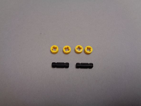
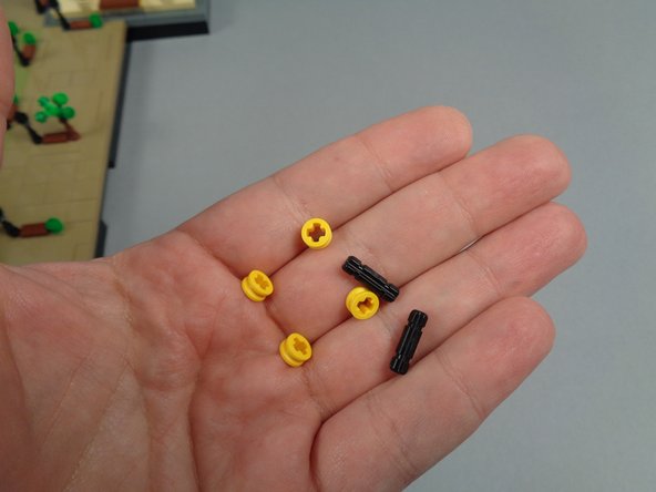
Also inside the large pink bag with the main controller will be six LEGO parts, which you will use to mount the controller inside the base of your Eiffel Tower.
-
Note that the color of the parts included with your kit may be different from the colors shown in these photos.
-
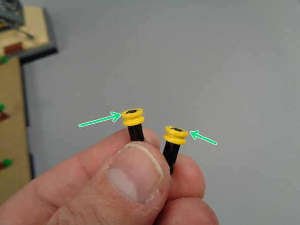
As shown in the second and third photos for this step, prepare the two short black axle parts by attaching one round bushing piece to the top of each axle.
-
Make sure the round bushing pieces are flush with the tops of each axle as shown by the green arrows in the third photo.
-
-
-
As shown in the photos for this step, take your main controller and connect the barrel plug from the power supply cable to the power input on the bottom of the controller board.
-
Make sure the barrel plug is firmly and fully inserted into the socket on the main controller board.
-
-
-
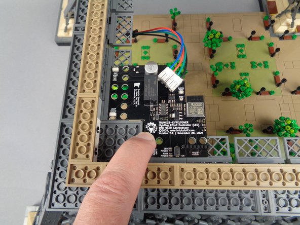
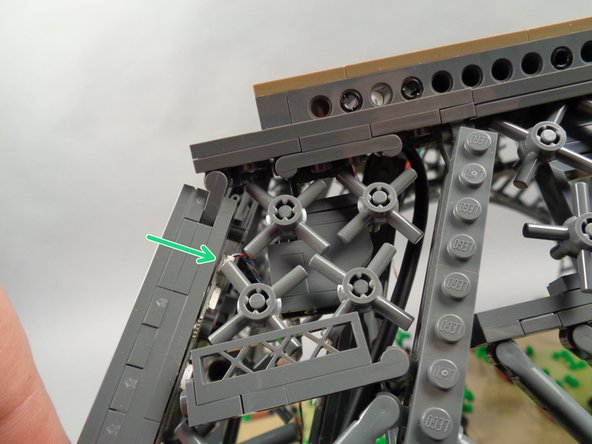
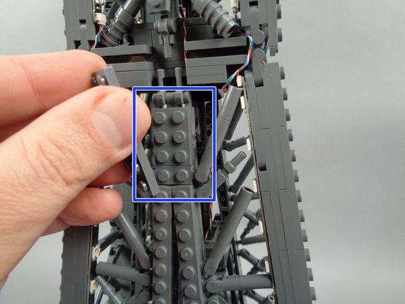
Position the main controller in the corner of the tower base as shown in the first photo for this step.
-
The main controller is specially designed to fit in the corner of the top of the tower base-- make sure it is positioned as shown in the first photo.
-
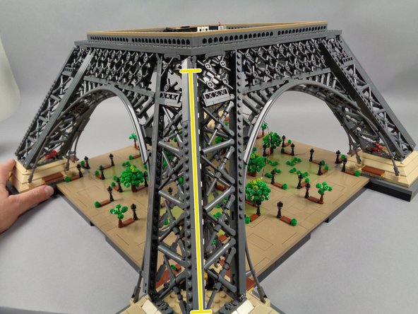
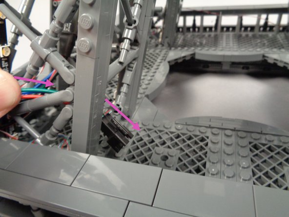
As shown in the second photo, press one of the axle pieces down through the hole in the main controller and through the opening in the LEGO fence piece in the tower frame below the controller.
-
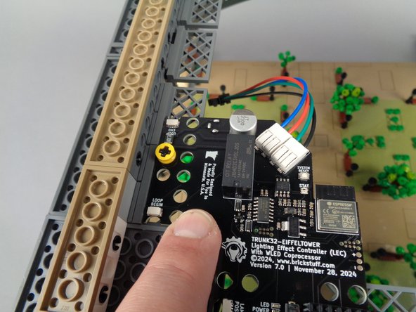
As shown in the third photo for this step, place the second axle piece directly next to the first.
-
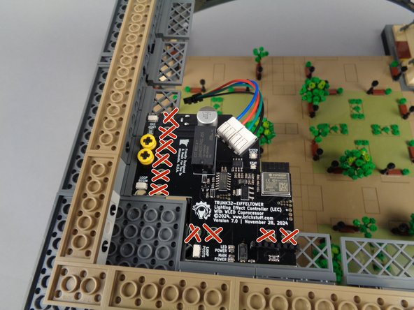
The main controller board has many holes, but you must mount the two axle pieces only in the holes shown. Do not insert any parts into any of the holes shown by a red "X" in the third photo. Any parts placed in any of these holes will prevent the middle tower section from sitting flat on the bottom base.
-
-
-
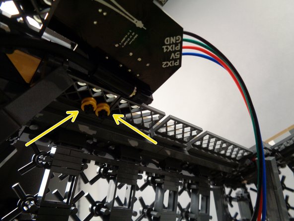
As shown by the yellow arrows in the first photo for this step, carefully press the remaining two round bushing pieces onto the bottom of the black axle parts. Press down from the top while pressing up from the bottom to make sure the top and bottom bushings hold the board tightly in place.
-
Your main controller should now look like the second photo for this step: firmly held in place in the top corner of your tower base.
-
-
-
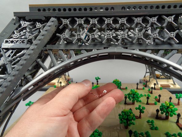
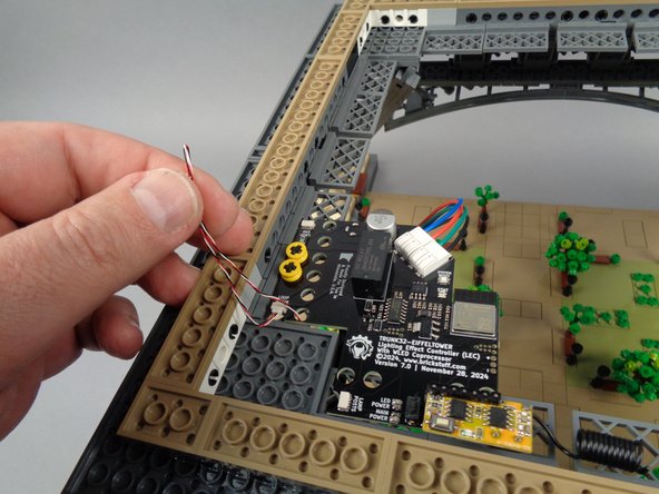
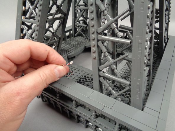
Open the pink bag from Box 1 with the handheld remote control transmitter and receiver. The green arrow in the first photo for this step shows the receiver board with coiled wire antenna.
-
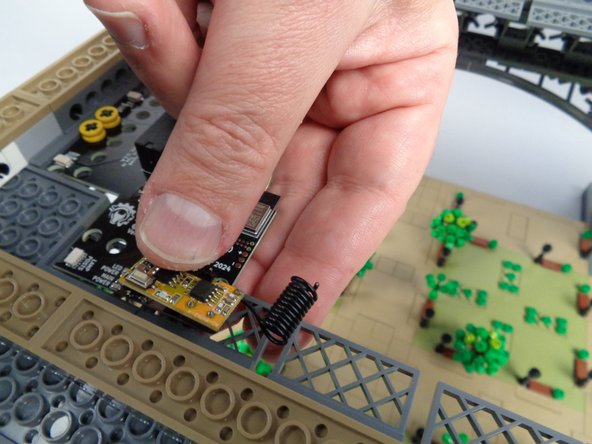
As shown in the second photo, carefully press the pins on the bottom side of the receiver board into the black connector on the top of the controller board.
-
There are seven pins on the receiver. As you insert it into the black connector (which has seven holes), make sure the pins are aligned to the holes. Do not force or bend any pins.
-
As shown by the blue circle in the second photo, make sure you insert the receiver board with its antenna facing to the right.
-
As shown in the third photo for this step, carefully press from both the top and bottom of the receiver board to fully insert it into its connector on the main controller.
-
-
-
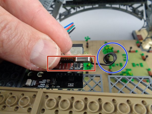
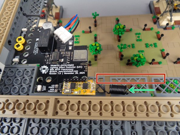
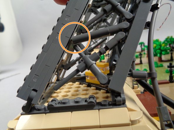
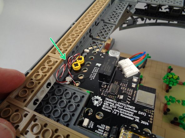
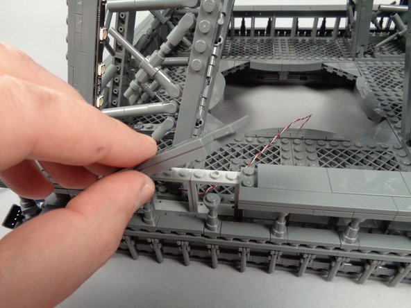
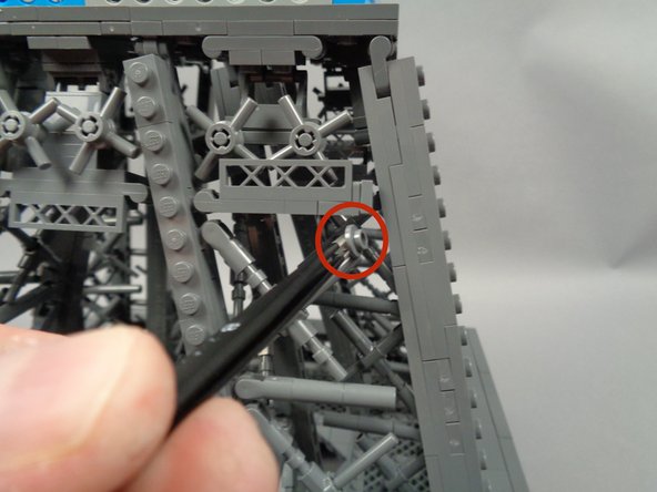
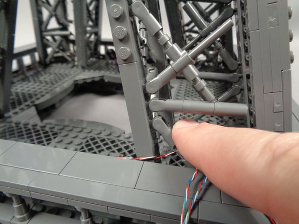
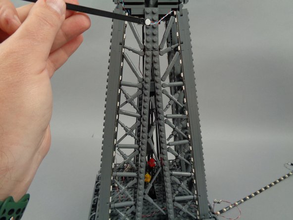
As shown by the green arrow in the photo for this step, carefully bend the antenna wire slightly so it runs parallel to the inner edge of the tower frame, away from the receiver board.
-
Make sure to keep the antenna out of the area shown by the red rectangle-- this will ensure the middle tower section fits on top without crushing the antenna wire.
-
-
-
You can now begin preparing the first set of eight light strips, for installation in the base level of your Eiffel Tower.
-
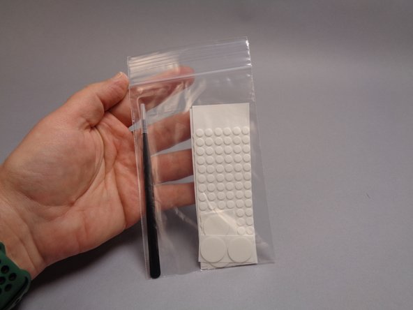
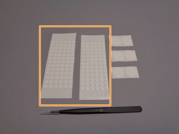
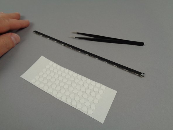
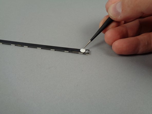
Your Brickstuff kit includes a clear plastic bag with sticky dots and tweezers inside, as shown in the photos for this step.
-
The orange rectangle in the second photo shows two sheets of small sticky dots. You will use the tweezers to attach these to the back side of all light strips used in this kit-- this will allow the strips to be easily attached to the frame of the tower.
-
-
-
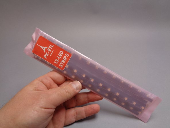
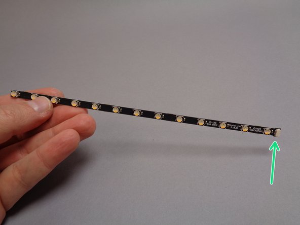
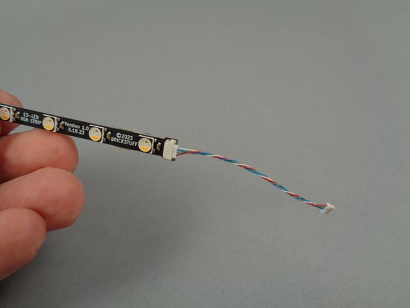
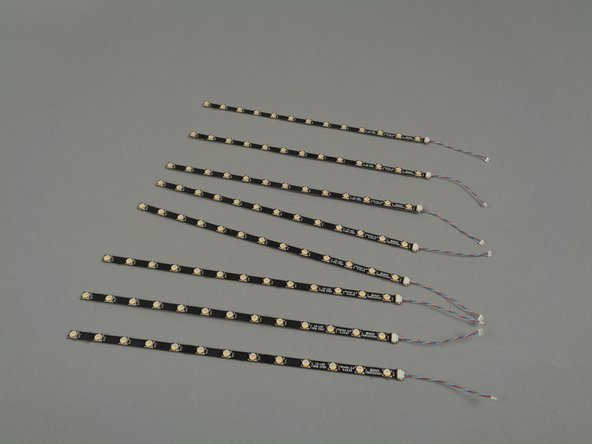
As shown in the first photo for this step, you will open the bag of 13-LED light strips next.
-
Do not tear this bag open-- use a pair of scissors to cut the top open, taking care to avoid cutting any light strips or LED lights.
-
There are 16 light strips in this bag. You will use eight of them for the tower base level.
-
The second photo shows the light strips-- note that there is a plug on one end, as shown by the green arrow.
-
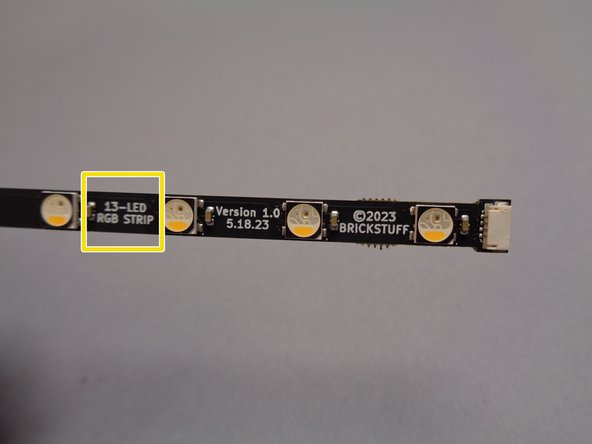
As shown by the yellow rectangle in the third photo, you can always identify the type of light strip you are working with by looking at label on the front of each strip.
-
-
-
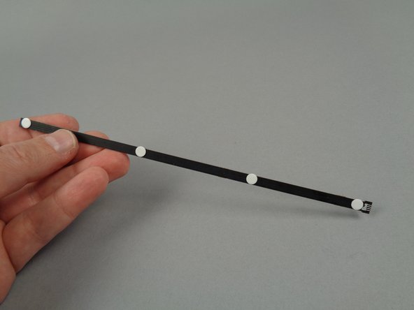
As shown in the photos for this step, use your tweezers to attach four sticky dots to the back of each of the eight 13-LED light strips you will use for the base tower level.
-
Use only four sticky dots per light strip, spacing them evenly along the length of each strip as shown in the third photo. Your Brickstuff kit includes enough sticky dots for all light strips.
-
-
-
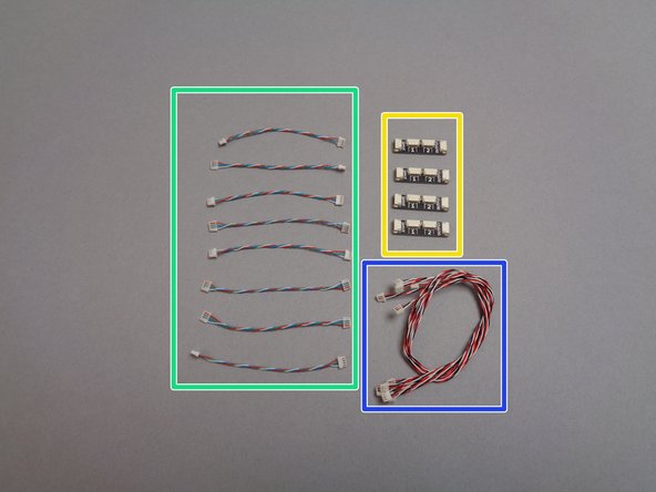
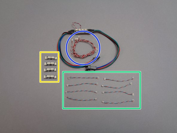
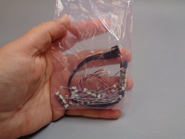
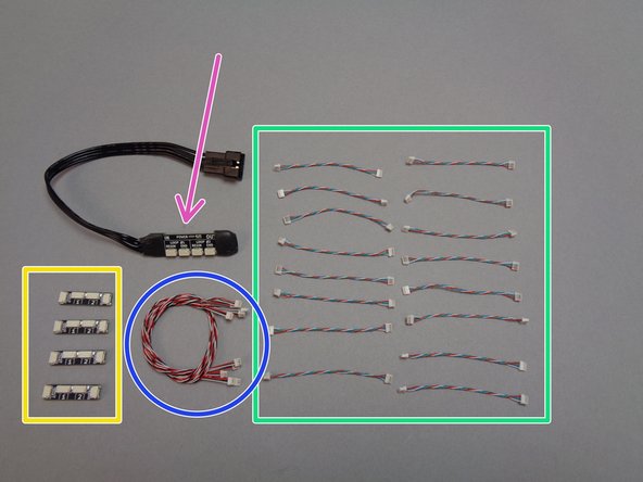
The first photo for this step shows the contents of the third and final pink bag that was included inside Box 1 of your Brickstuff kit.
-
The green box shows the eight short 4-wire cables you will connect to the end of each light strip.
-
The yellow box shows the four adapter boards you will use to create a chain connecting all light strips on this level.
-
The blue box shows the 3-wire cables you will use to connect the adapter boards in a loop with the main controller.
-
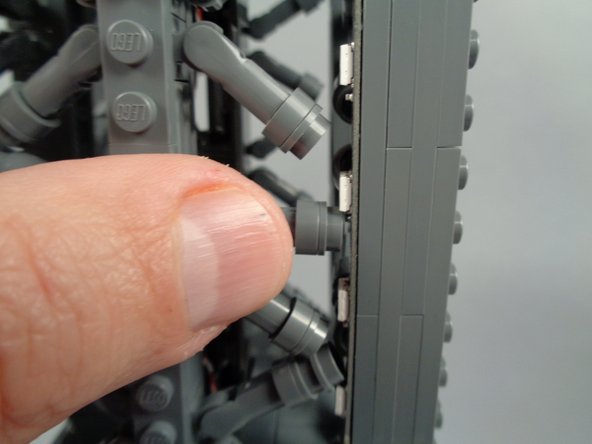
As shown in the second photo for this step, carefully connect one 4-wire cable to the plug on the end of each light strip.
-
Plugs can be inserted only one way. Do not force plugs. To insert, press with your finger. When a plug is fully inserted, you will feel a soft "click" with your fingernail.
-
As shown in the third photo for this step, you should now have 4-wire cables connected to the end of all eight light strips.
-
-
-
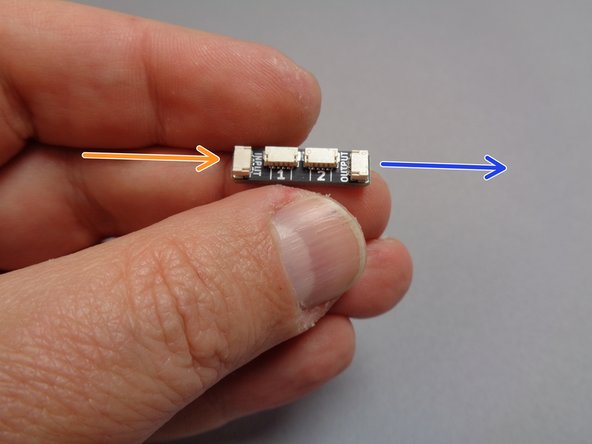
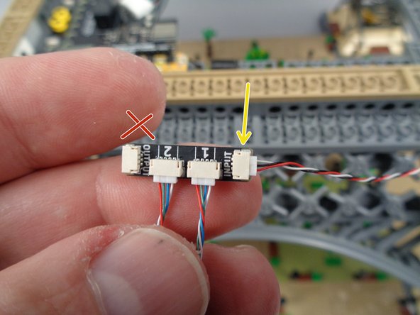
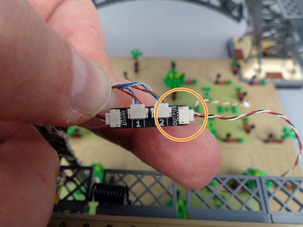
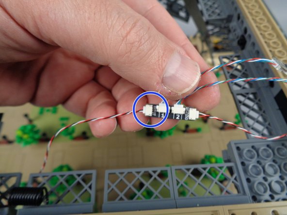
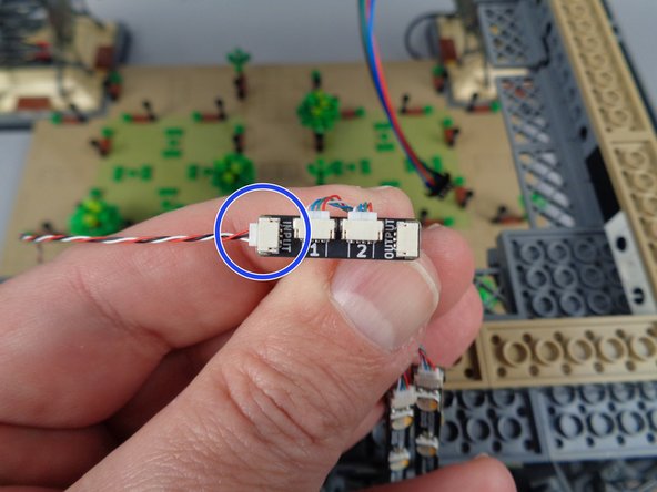
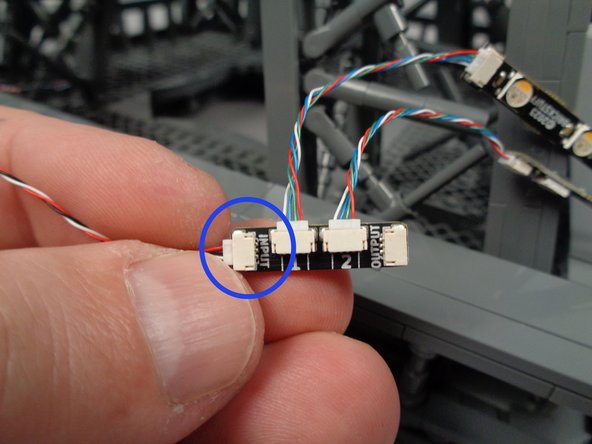
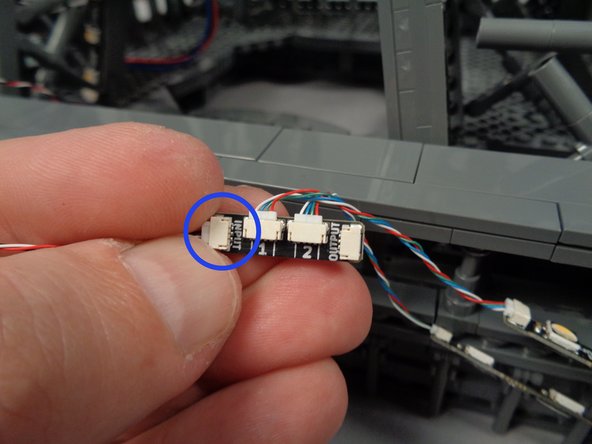
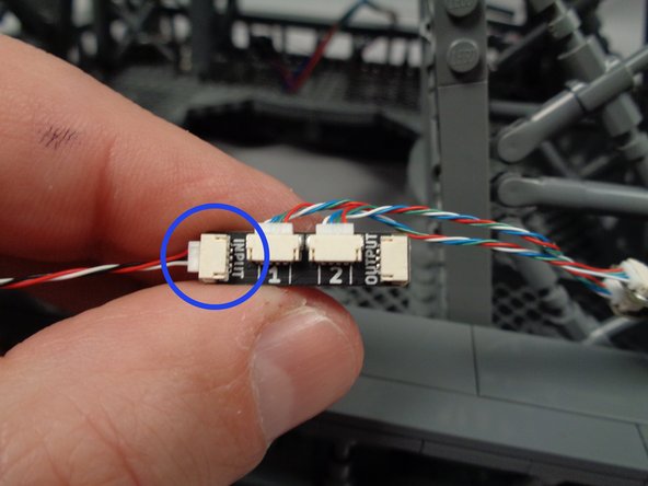
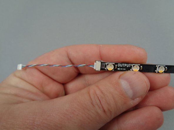
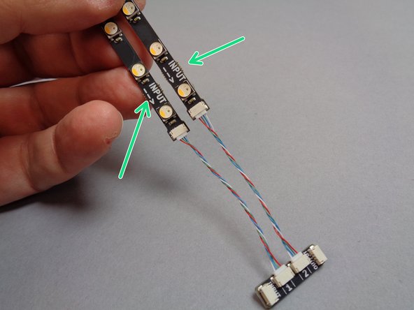
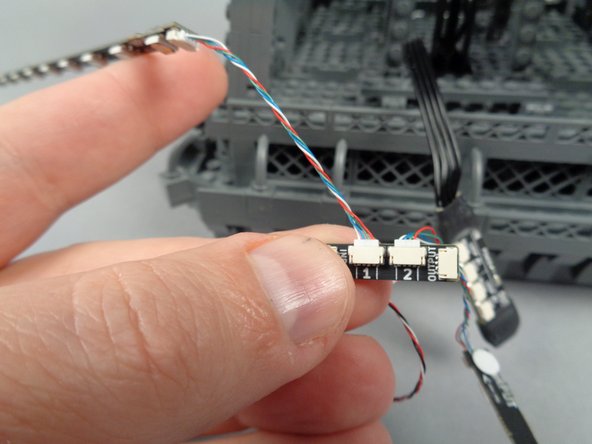
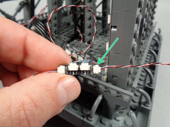
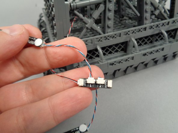
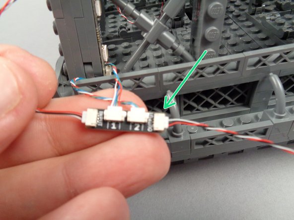
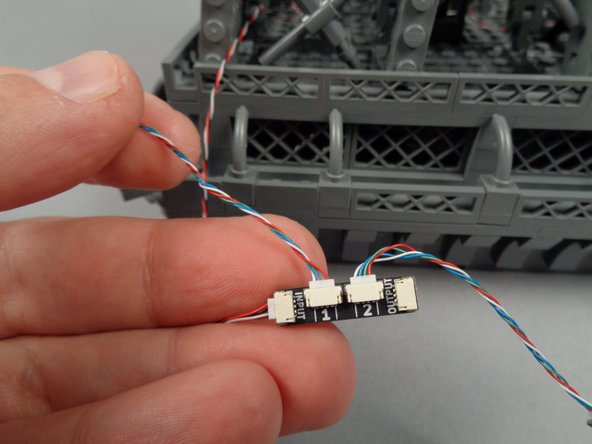
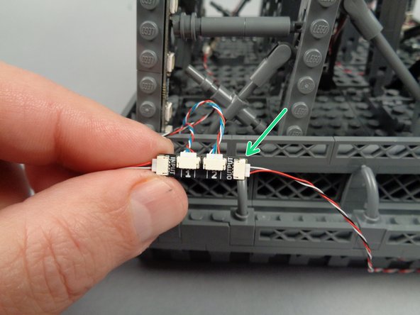
The first photo for this step shows a close-up of one of the adapter boards. In order for your light kit to work properly, it is essential that you connect cables to the board in the exact order shown in the following steps.
-
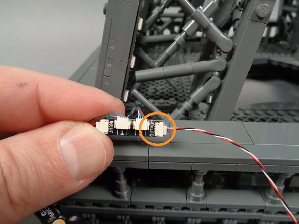
The main controller operates each light strip in a directional chain. As shown by the orange arrow in the first photo, there is a plug labeled INPUT on each adapter. This is where the incoming control signal wire will be connected.
-
As shown by the blue arrow in the first photo, there is also a plug on each adapter labeled OUTPUT. This is where the outgoing control signal wire will be connected.
-
The most common mistake made during installation is mixing up the INPUT and OUTPUT plugs (connecting two INPUTs or two OUTPUTs). Doing so will not damage any lights, but it will prevent lights further down the chain from working. Always make sure to follow the steps in this guide, so you avoid mixing up INPUTs and OUTPUTs.
-
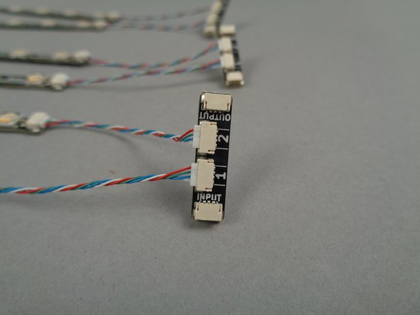
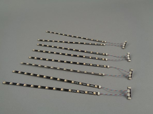
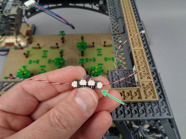
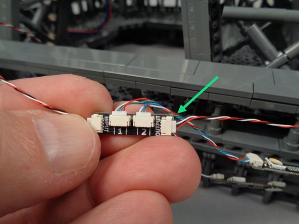
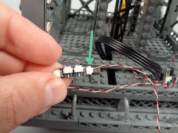
As shown in the second photo, connect the short 4-wire cables to the plugs labeled 1 and 2 on each adapter board.
-
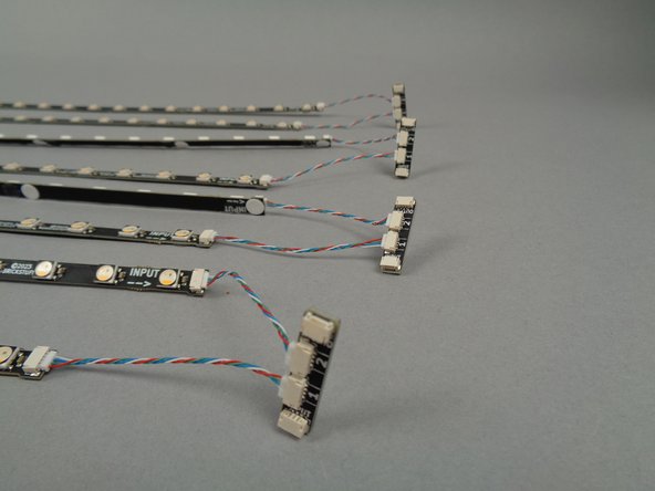
When you have finished connecting all wires, your setup should look like the third photo in this step, with all eight light strips connected in four pairs to the four adapter boards.
-
-
-
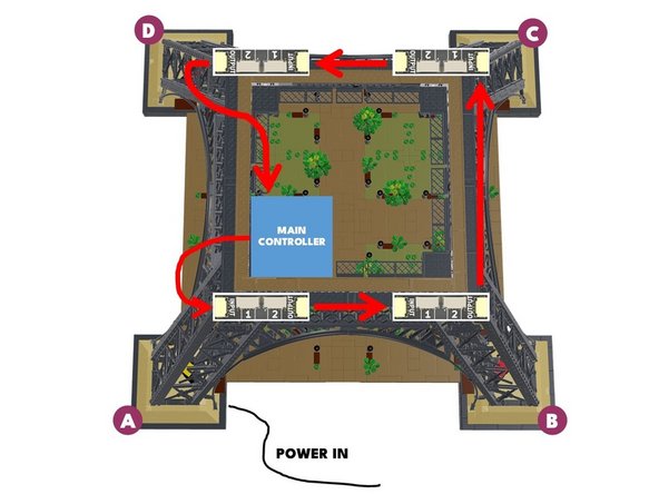
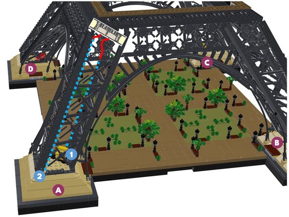
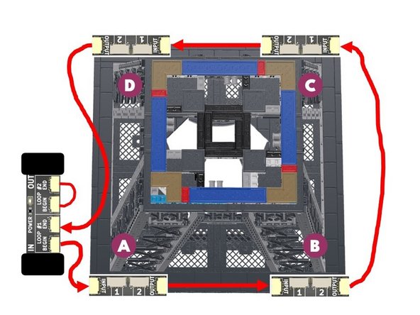
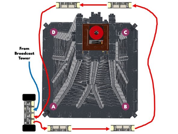
Now you will begin connecting the eight light strips in a loop around the base level of your Eiffel Tower.
-
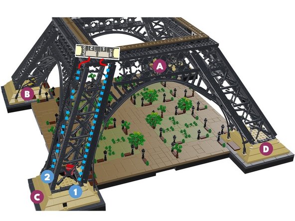
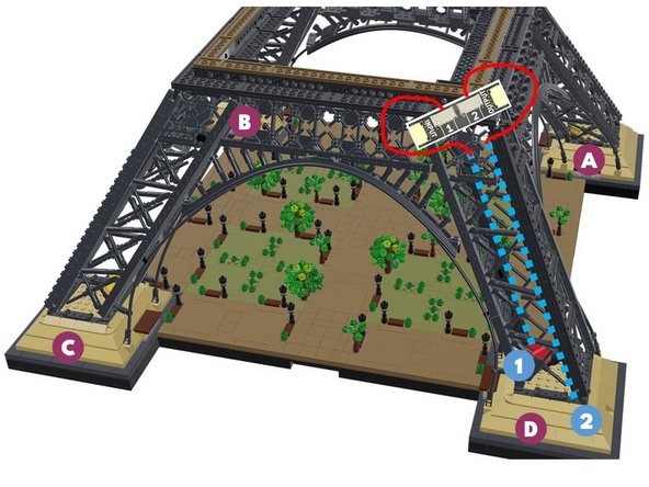
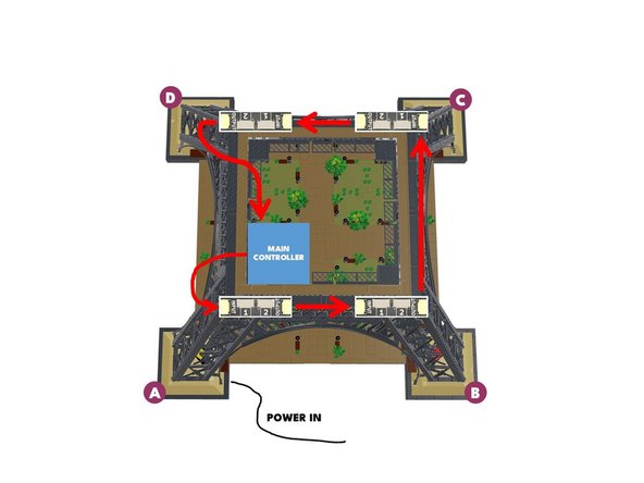
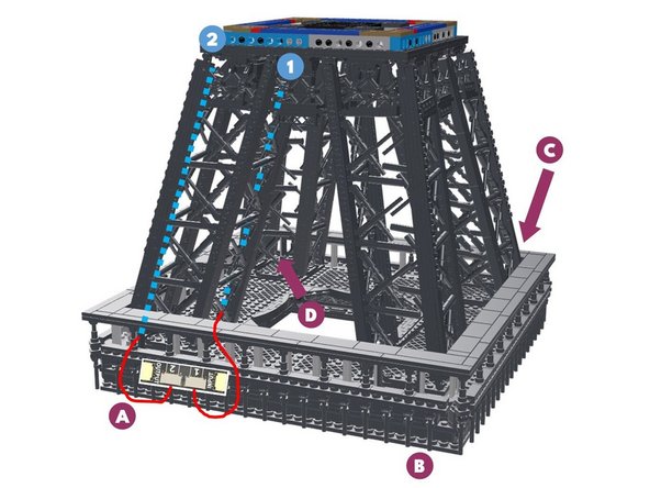
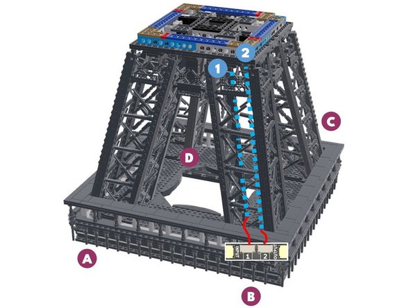
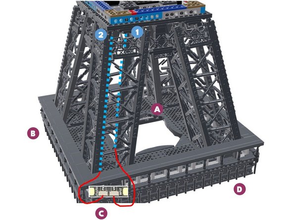
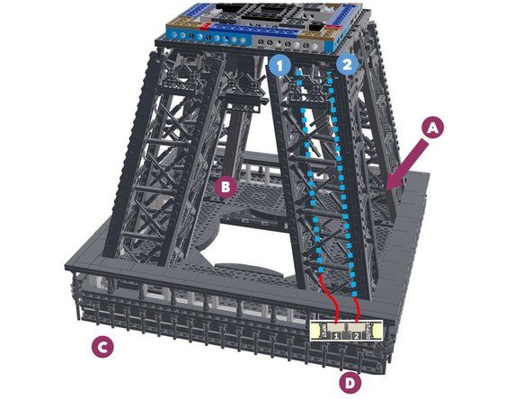
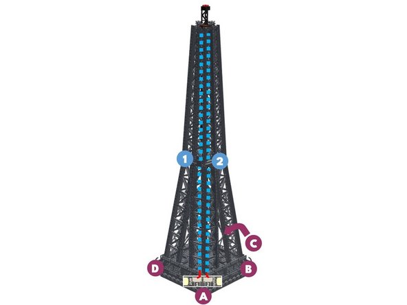
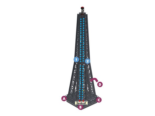
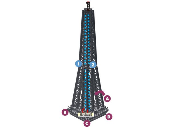
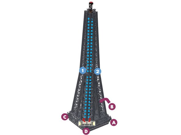
Study the illustration for this step carefully.
-
Note that each "foot" or pillar of the base is labeled with a letter (A-D), beginning with the location where power is connected and the main controller is located.
-
From pillar "A", you will connect the INPUTs and OUTPUTs of each adapter board in a circle that moves counterclockwise from the main controller, around the base in a loop, and then back to the main controller.
-
The following steps walk you through this process in detail.
-
-
-
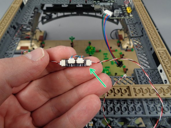
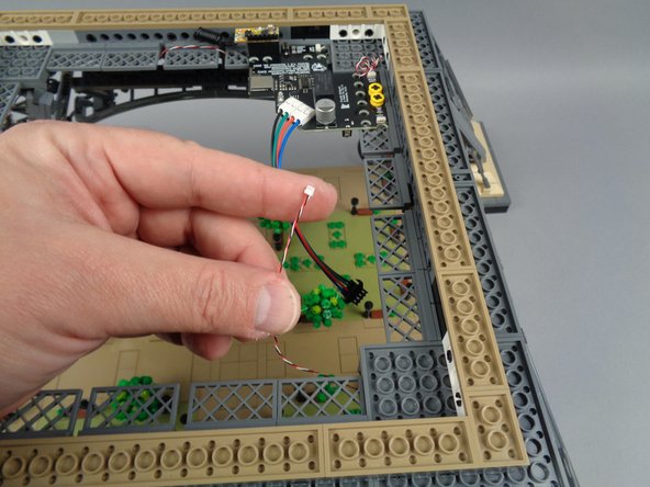
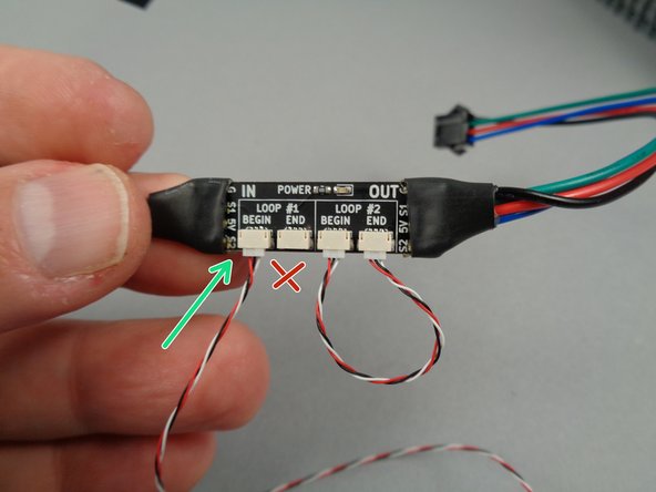
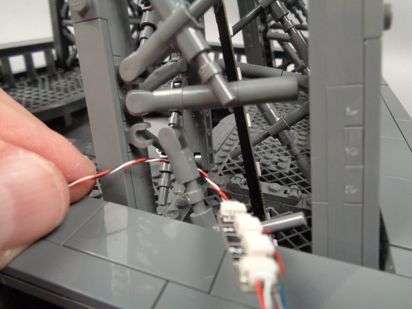
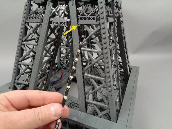
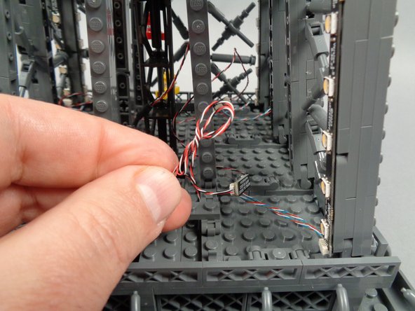
As shown by the yellow arrow in the photo for this step, connect one of the 3-wire control cables to the INPUT plug on one of the adapter boards. (you can select any adapter board as the first in the chain)
-
As shown by the red "X" in the photo, do not connect anything to the OUTPUT plug yet.
-
-
-
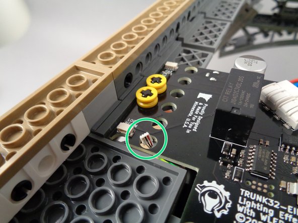
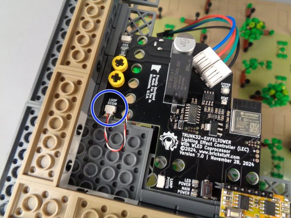
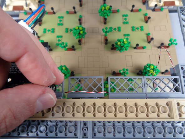
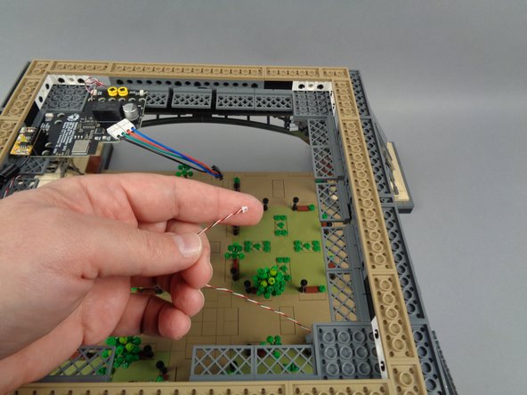
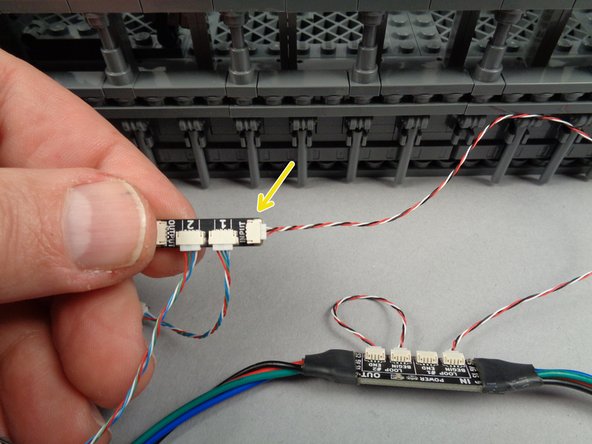
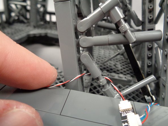
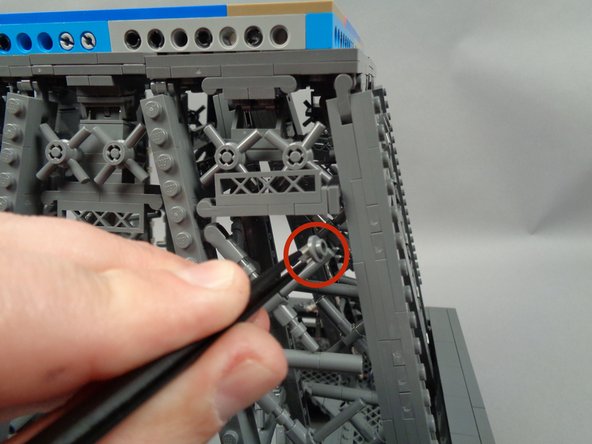
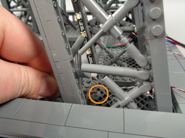
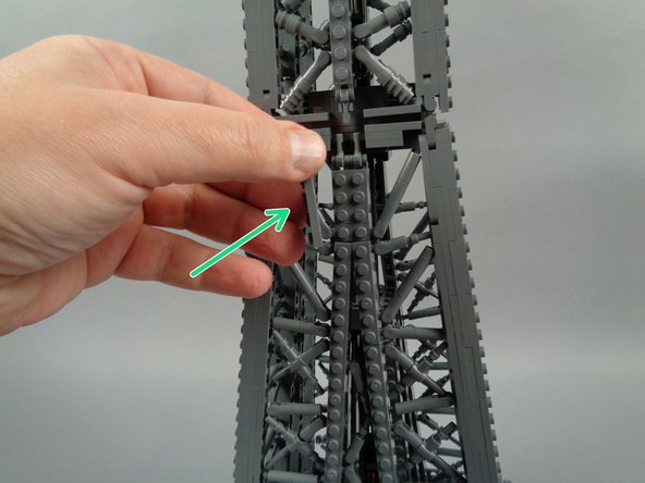
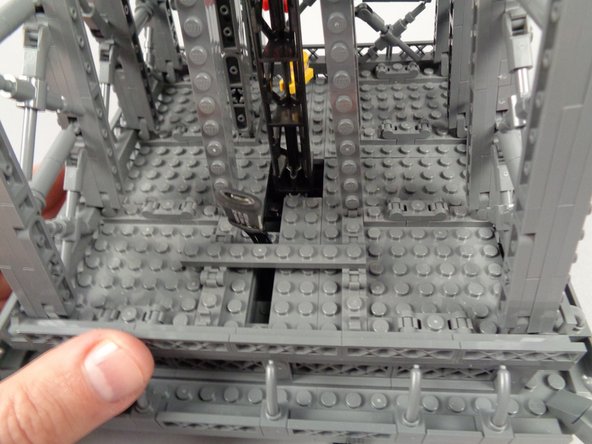
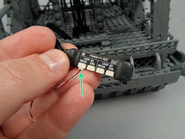
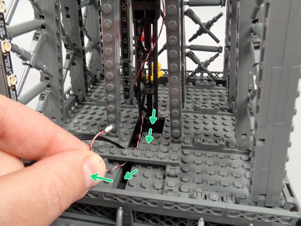
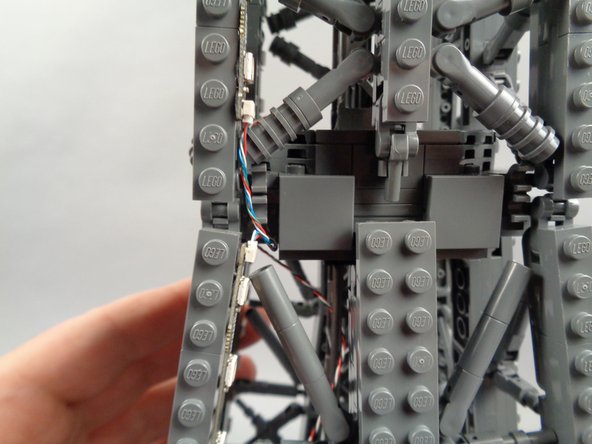
As shown by the green circle in the first photo for this step, push the other end of the control cable up through the hole in the main controller next to the plug labeled "LOOP BEGIN".
-
As shown by the blue circle in the second photo, carefully connect the cable to the "LOOP BEGIN" plug on the main controller, making sure the plug is fully inserted.
-
-
-
The first photo for this step shows how the connections to your first adapter board should look, with the cable connected to the INPUT plug on the adapter running back to the main controller.
-
As shown by the orange circle in the second photo, take a second control cable and connect it to the OUTPUT plug on the adapter board.
-
Leave the other end of this second cable unconnected for now.
-
-
-
The illustration in this step shows the arrangement for the two light strips in the first pillar ("A") of the tower. (you can click on the image to enlarge it if needed)
-
Note the two numbers (1 and 2) in the light blue circles in the illustration. These numbers correspond to the numbers 1 and 2 on each adapter board.
-
For best visual appearance, it is recommended to install your light strips using the same arrangement of strips 1 and 2 in each pillar.
-
In our diagram, we have strip #1 positioned on the inside edge of the pillar, pointing outward, and strip #2 positioned on the outside edge of the pillar, pointing inward.
-
If this seems confusing now, it will become clear as you go around the base installing the strips in the coming steps.
-
-
-
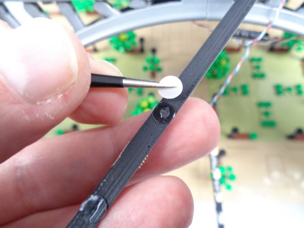
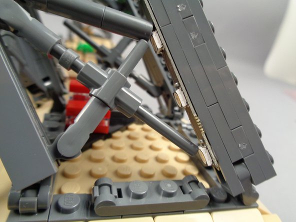
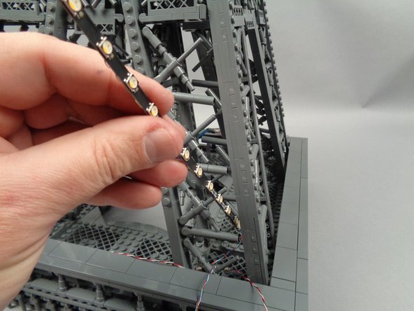
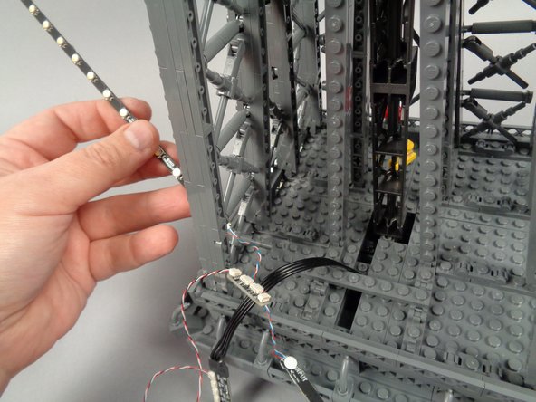
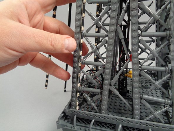
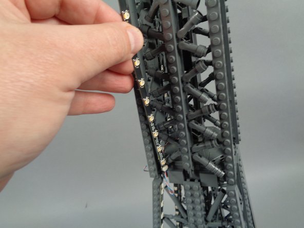
Begin by removing the backs of the four sticky dots on the first light strip as shown in the first photo for this step.
-
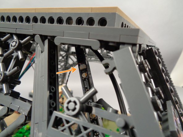
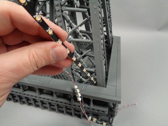
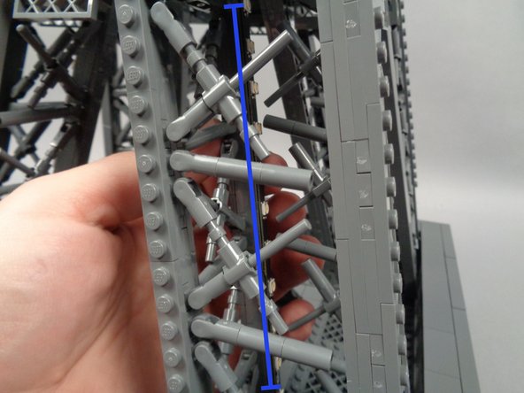
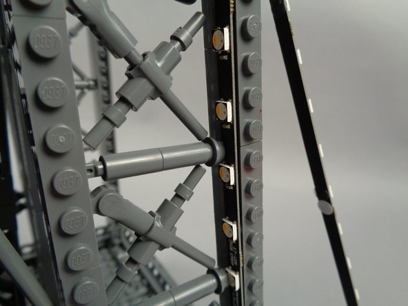
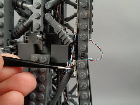
As shown by the orange arrow in the second photo, carefully pass the light strip connected to plug #1 on the adapter board down through the top of the first pillar with its connecting plug at the top of the pillar.
-
Using two fingers, gently press the front and back sides of the pillar to attach the light strip to the pillar.
-
The third photo shows the strip mounted to the inside edge of the pillar.
-
Throughout the installation process, you may find it necessary to re-position sections of the tower bracing bars to make room for the LED lights on the strips. Gently move each element up or down as needed to make room for the light strip so it can firmly attach to the flat surface.
-
-
-
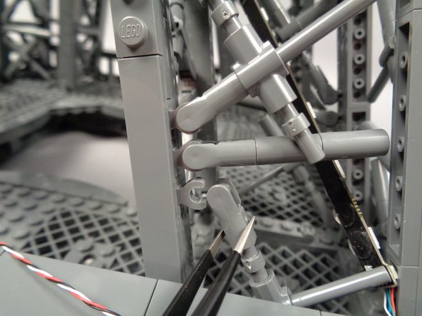
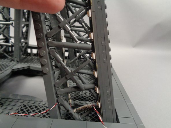
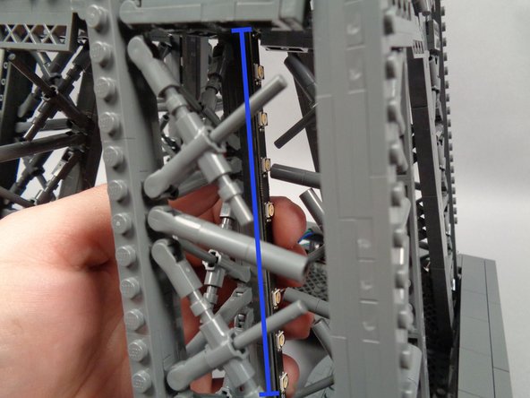
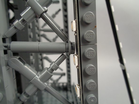
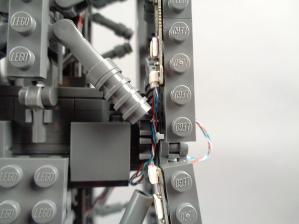
As shown in the photos for this step, repeat the same process to slide the second light strip into the pillar interior, then down the pillar to attach to the outer edge, facing inward toward the first light strip.
-
The green arrow in the first photo shows the connecting plug for the second light strip (connected to plug #2 on the adapter board) attached with the plug at the top of the pillar.
-
The orange circle in the second photo shows how one of the large cross-brace parts in the tower frame needed to be moved slightly to make room for the LED light on the strip to fit.
-
-
-
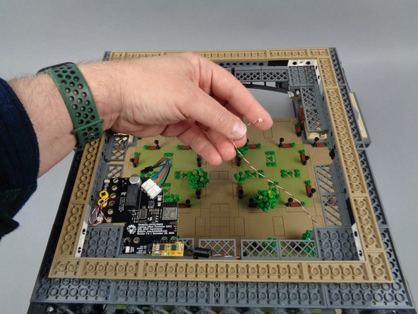
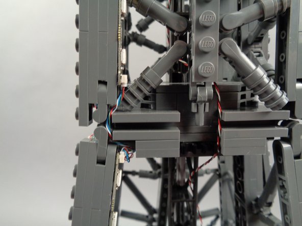
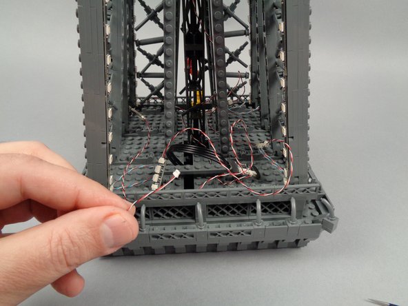
As shown in the first photo for this step, you should now have one control wire hanging loose inside your tower base.
-
As shown in the second and third photos, you can gently pull any excess wire from the first control cable up through the hole in the main controller, then coil it up to hide any excess wire.
-
As shown by the green arrow in the third photo, make sure to move all wire to the edge of the main controller. Keep it away from the row of holes in the main controller board (this is where the middle section of your Eiffel Tower will sit, and this area needs to be clear of wires in order for the middle section to sit flat on top of the base).
-
-
-
Next, you will rotate your Eiffel tower in a clockwise direction-- this is the same direction the loose control cable from the previous step is pointing toward.
-
The illustration for this step shows the tower rotated so that pillar "A" (where you installed the first light strip) is to the left, and pillar "B" (where you will install the next strip) is on the right.
-
You can click on the image to enlarge it if needed.
-
To install the next light strip pair, you will repeat the same process as you used with the first, positioning the strip connected to plug #1 on the adapter board to the inside of the pillar pointing outward, and positioning the strip connected to plug #2 of the adapter board on the outside edge of the pillar pointing inward.
-
-
-
Take another light strip pair with connected adapter board and, as shown by the green arrow in the photo for this step, connect a 3-wire control cable to the OUTPUT plug on the adapter board.
-
Leave the other end of the control cable unconnected for now.
-
-
-
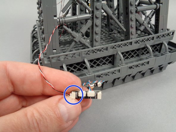
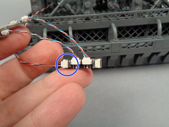
As shown in the first photo for this step, carefully reach under the center of your tower to find the loose control cable coming from the first adapter board and first set of light strips.
-
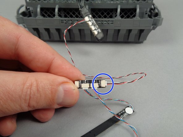
As shown by the blue circle in the second photo for this step, connect the end of the control cable coming from the first adapter board to the INPUT plug on the second adapter board.
-
-
-
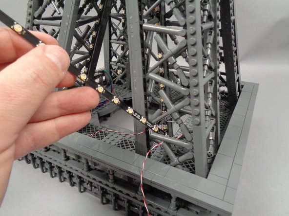
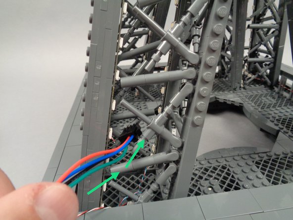
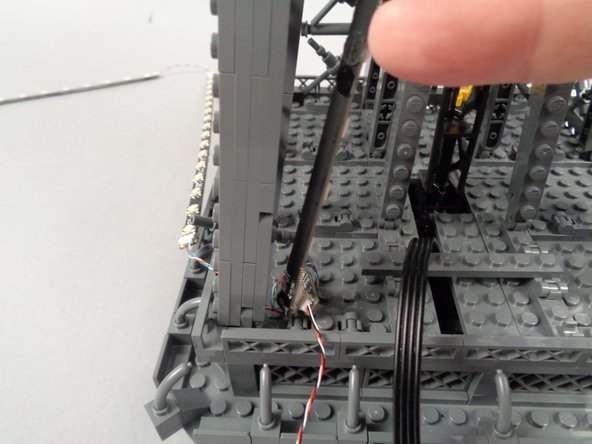
Use your tweezers to remove the backs of the sticky dots on the next two light strips, and carefully pass the ends of both strips down into the center of the structure as shown by the green arrow in the first photo for this step.
-
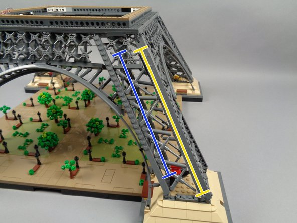
The blue and yellow lines in the second photo show both strips attached to the insides of the pillar supports.
-
The blue line shows the strip connected to plug #1 on the adapter board mounted on the inside facing outward.
-
The yellow line shows the second strip connected to plug #2 on the adapter board mounted on the outside facing inward.
-
The third photo for this step shows a closeup of the second strip, showing how some decorative bracing elements have been moved to make room for the LED lights.
-
Make sure both strips are firmly secured to the support structure by gently pressing with two fingers (one on the outside of the support and one on the inside).
-
-
-
As shown in the photo for this step, you can loop any excess control wire over one of the fence elements to hide it if it hangs down.
-
-
-
Next, you will rotate your Eiffel tower in a clockwise direction again-- this is the same direction the loose control cable from the previous step is pointing toward.
-
The illustration for this step shows the tower rotated so that pillar "B" (where you installed the previous light strip) is to the left, and pillar "C" (where you will install the next strip) is in the center.
-
You can click on the image to enlarge it if needed.
-
To install the next light strip pair, you will repeat the same process as you used with the previous two, positioning the strip connected to plug #1 on the adapter board to the inside of the pillar pointing outward, and positioning the strip connected to plug #2 of the adapter board on the outside edge of the pillar pointing inward.
-
-
-
Take another light strip pair with connected adapter board.
-
As shown in the first photo for this step, carefully reach under the center of your tower to find the loose control cable coming from the second adapter board and second set of light strips.
-
As shown by the blue circle in the second photo for this step, connect the end of the control cable coming from the second adapter board to the INPUT plug on the third adapter board.
-
As shown by the green arrow in the third photo for this step, connect a 3-wire control cable to the OUTPUT plug on the third adapter board.
-
Leave the other end of the control cable unconnected for now.
-
-
-
Using the same process as with the previous two light strip pairs, mount the fifth and sixth light strip in the third pillar with the strip connected to plug #1 on the adapter board on the inside facing outward and the strip connected to plug #2 on the adapter board on the outside facing inward.
-
The blue line in the first photo for this step shows the light strip connected to plug #1 on the adapter board.
-
The yellow line in the second photo for this step shows the light strip connected to plug #2 on the adapter board.
-
Make sure both strips are firmly secured to the support structure by gently pressing with two fingers (one on the outside of the support and one on the inside).
-
-
-
Next, you will rotate your Eiffel tower in a clockwise direction again-- this is the same direction the loose control cable from the previous step is pointing toward.
-
The illustration for this step shows the tower rotated so that pillar "C" (where you installed the previous light strip pair) is to the left, and pillar "D" (where you will install the final strip pair) is on the right.
-
You can click on the image to enlarge it if needed.
-
To install the final light strip pair, you will repeat the same process as you used with the other pairs, positioning the strip connected to plug #1 on the adapter board to the inside of the pillar pointing outward, and positioning the strip connected to plug #2 of the adapter board on the outside edge of the pillar pointing inward.
-
-
-
Take the final light strip pair with connected adapter board.
-
As shown in the first photo for this step, carefully reach under the center of your tower to find the loose control cable coming from the previous adapter board and first set of light strips.
-
As shown by the blue circle in the second photo for this step, connect the end of the control cable coming from the third adapter board to the INPUT plug on the fourth adapter board.
-
As shown by the green arrow in the photo for this step, connect your final 3-wire control cable to the OUTPUT plug on the adapter board.
-
Leave the other end of the control cable unconnected for now.
-
-
-
Using the same process as with the previous three light strip pairs, mount the 7th and 8th light strip in the fourth pillar with the strip connected to plug #1 on the adapter board on the inside facing outward and the strip connected to plug #2 on the adapter board on the outside facing inward.
-
Make sure both strips are firmly secured to the support structure by gently pressing with two fingers (one on the outside of the support and one on the inside).
-
-
-
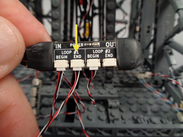
Now that you have mounted all eight light strips and connected each pair in a loop starting at the "LOOP BEGIN" plug on the main controller, you will now complete the control loop using the last control cable.
-
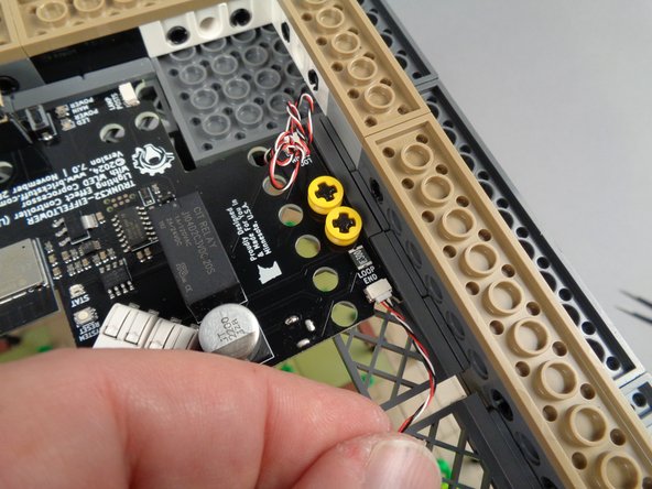
The first photo for this step shows the loose control cable connected to the OUTPUT plug on the fourth adapter board.
-
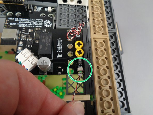
As shown by the green circle in the second photo for this step, connect the end of the control cable to the plug labeled "LOOP END" on the main controller.
-
Make sure the plug is fully inserted, as shown in the third photo for this step.
-
-
-
As shown by the green rectangle in the photo for this step, clean up any loose hanging control wires by looping them over the fence elements in the tower frame.
-
-
-
The illustration for this step is the same as in Step 26 before you began installing the strips. Take another look at the diagram (click on the illustration if needed to enlarge it) and make sure you have connected your control cables and adapter boards in the same sequence and direction as shown.
-
Next, you will connect power and complete the first test of your lighting setup.
-
-
-
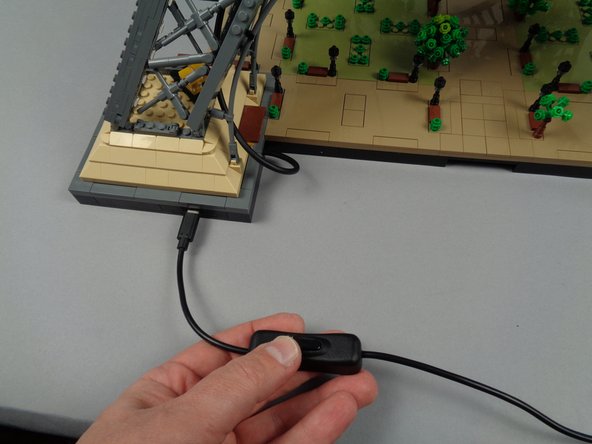
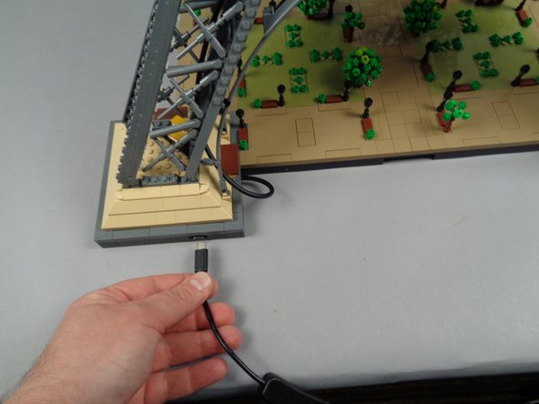
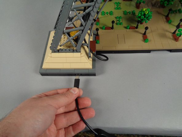
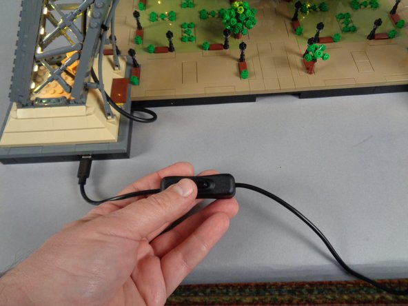
Connect your USB-C power supply to mains power. As shown in the first two photos for this step, connect the USB-C power plug to the connector in the base of your Eiffel Tower.
-
International customers can use a plug converter to match their local mains plug. The USB-C power supply provided with your Brickstuff kit can operate on any global mains voltage.
-
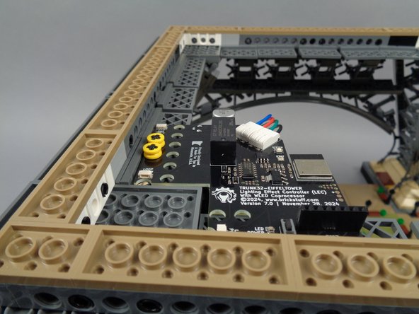
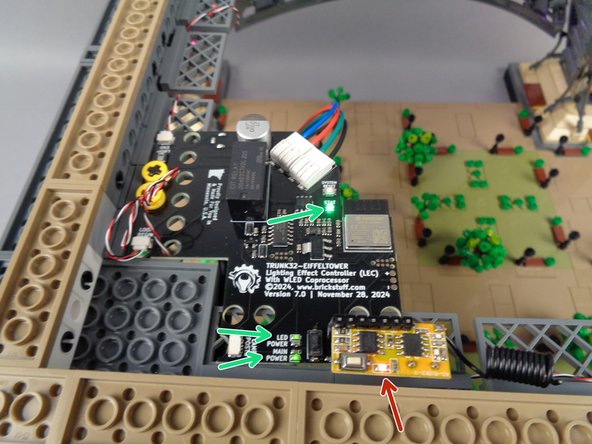
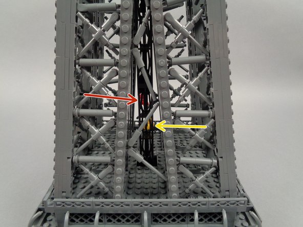
When power is turned on, three green LED lights should come on as shown by the three green arrows in the third photo.
-
The large LED light in the center of the photo will pulse on and off.
-
The other two LED lights will be steady on.
-
As shown by the red arrow in the third photo, a red LED light on the remote receiver board should also turn on.
-
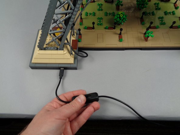
If you do not see any lights turn on when you connect power, check the switch on the power wire as shown in the second photo.
-
If only one green LED light comes on, press the "A" button on your remote control once. This should turn the LED power on.
-
-
-
The video in this step shows all eight light strips in the lower tower section running different lighting effects.
-
When your power is on, you should see similar effects in your tower.
-
The specific patterns shown is not important-- what you are looking for is that all eight light strips are active and showing colored lights.
-
If some light strips work, but not all, there is likely a connection problem somewhere in your control cable chain. Double check the plug connections on each adapter board and the connections to each light strip.
-
Something else to double-check if not all of your light strips are working: Look back at the diagram in Step 47 (two steps back) to make sure you have the INPUTs and OUTPUTs of each adapter board connected correctly.
-
If there is a mix-up with any of these connections (two INPUTs or two OUTPUTs connected, for example), this will cause lights further down the chain to stop working. While this will not damage any lights, it will prevent the control signal from reaching all strips.
-
If your Eiffel Tower lights are working as shown in the video, you can continue with installation and move to the second tower section.
-
-
-
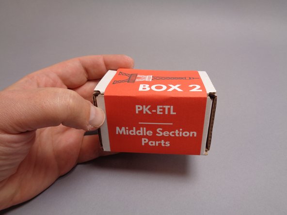
As shown in the first photo for this step, you will continue installation of your light kit with the parts included in Box 2.
-
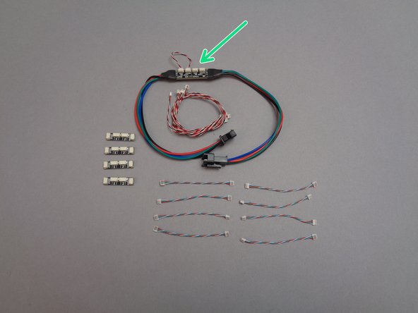
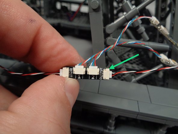
The second photo for this step shows the parts contained in the pink bag inside Box 2. Most of the parts are the same as those you saw in Box 1, with the exception of the inter-level connecting board shown by the green arrow.
-
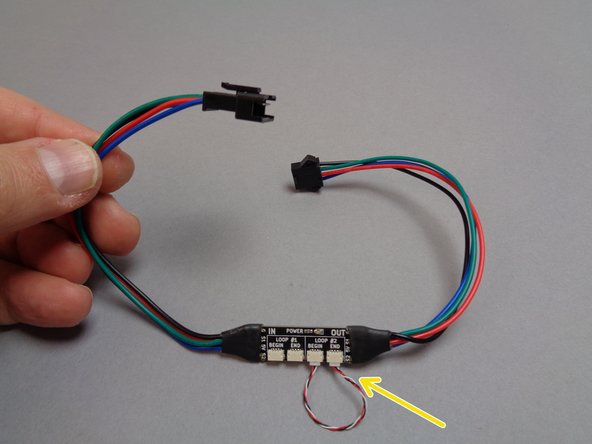
The third photo shows the inter-level connecting board. This board has large plugs on both ends, which are used to connect lights between different levels in your Eiffel Tower.
-
As shown by the yellow arrow in the third photo for this step, the inter-level connecting board also has a short control cable already connected in a loop with two plugs on the board. Leave this cable connected.
-
-
-
In Step 23, you opened the bag of 13-LED light strips, and you used eight of these for the lower tower level. You will use the remaining eight strips from this bag for the middle level.
-
As shown in the photos for this step, use your tweezers to attach four sticky dots to the back of each of the eight 13-LED light strips you will use for the middle tower level.
-
Use only four sticky dots per light strip, spacing them evenly along the length of each strip as shown in the third photo. Your Brickstuff kit includes enough sticky dots for all light strips.
-
-
-
The first photo for this step shows the contents of Box 2 of your Brickstuff kit.
-
The green box shows the eight short 4-wire cables you will connect to the end of each light strip.
-
The yellow box shows the four adapter boards you will use to create a chain connecting all light strips on this level.
-
The blue box shows the 3-wire cables you will use to connect the adapter boards in a loop with the inter-level connecting board.
-
As shown in the second and third photos for this step, connect one short 4-wire cable to the plug on the end of each light strip.
-
-
-
As shown in the photos for this step, connect the short 4-wire cables to the plugs labeled 1 and 2 on each adapter board.
-
When you have finished connecting all wires, your setup should look like the second photo in this step, with all eight light strips connected in four pairs to the four adapter boards.
-
-
-
Now you will begin connecting the eight light strips in a loop around the middle level of your Eiffel Tower. The first illustration for this step shows the connections and flow.
-
The connecting and mounting process will largely be the same as it was with the base level. The main difference with the middle level is you will be creating a loop with the inter-level connecting board, not the main controller as in the base level.
-
One other difference with attaching the light strips in the middle level is that the fit will be tighter, since the sloping pillars become more narrow. You will need to remove several LEGO pieces to make the strips fit, as shown in the following steps.
-
The second illustration for this step shows how the light strips in the center section will be positioned so they create a visual line from the bottom edge to the top edge of the Tower.
-
-
-
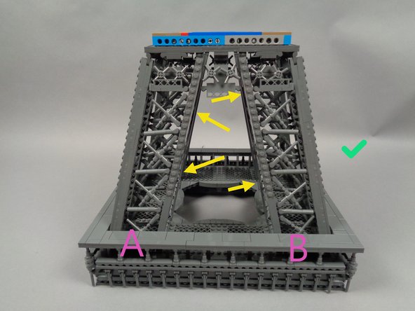
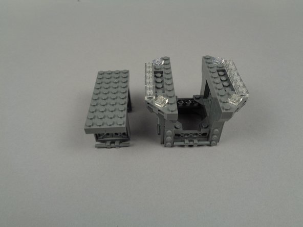
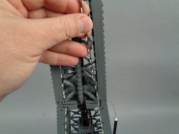
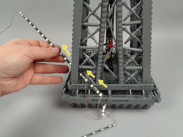
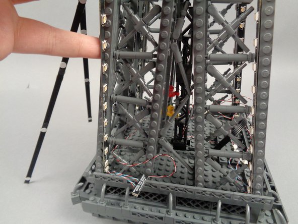
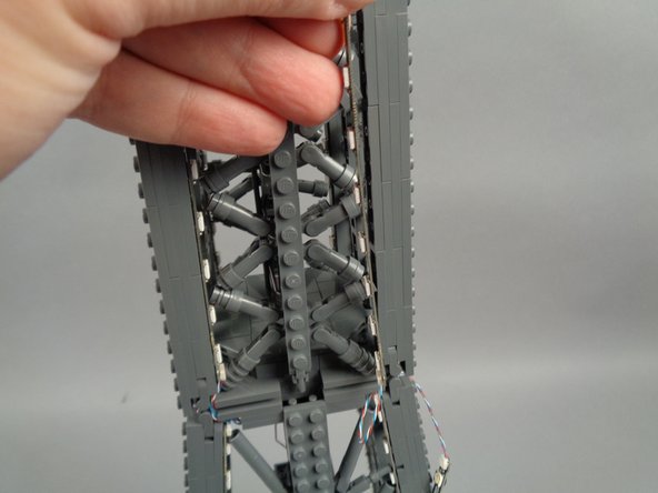
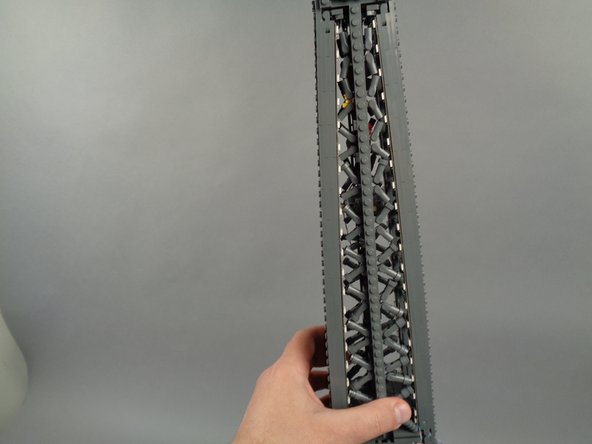
The two photos for this step show how you should position your Tower's middle section when working to install the light strips.
-
The yellow arrows in the first photo show how to correctly position your Tower's middle section. The studs going down the side should be in the CENTER, and the EDGE should not have studs.
-
The blue arrows in the second photo show the INCORRECT way, with the studs down the side being on the EDGE.
-
-
-
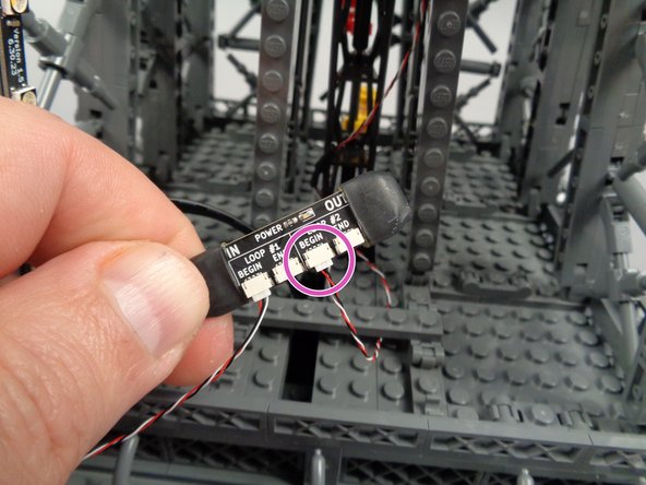
As shown by the green arrow in the first photo for this step, take one of the 3-wire control cables and connect it to the plug labeled BEGIN. Do not connect anything to the END plug at this time.
-
As shown by the yellow arrow in the second photo for this step, connect the other end of the control cable to the INPUT plug on one of the adapter boards. (you can select any adapter board as the first in the chain)
-
Remember that proper operation of your light kit depends on wires being connected to INPUTs and OUTPUTs exactly as shown.
-
-
-
The illustration in this step shows the arrangement for the two light strips in the first pillar ("A") of the tower. (you can click on the image to enlarge it if needed)
-
Note the two numbers (1 and 2) in the light blue circles in the illustration. These numbers correspond to the numbers 1 and 2 on each adapter board.
-
For best visual appearance, it is recommended to install your light strips using the same arrangement of strips 1 and 2 in each pillar.
-
In our diagram, we have strip #1 positioned on the inside edge of the pillar, pointing outward, and strip #2 positioned on the outside edge of the pillar, pointing inward.
-
-
-
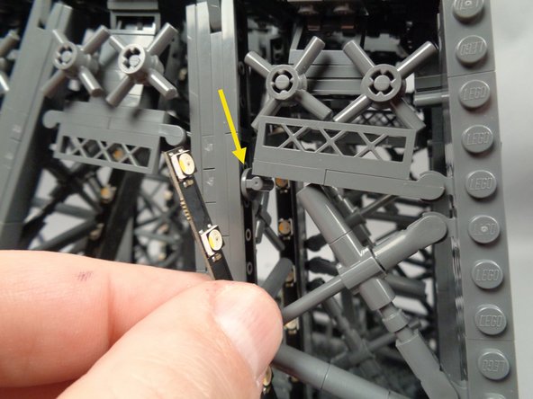
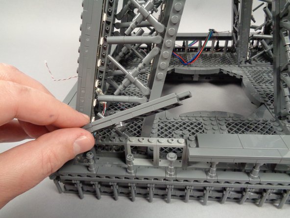
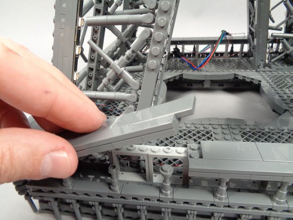
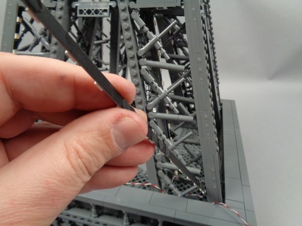
As shown by the red circle in the first photo for this step, remove the small piece that supports the horizontal walkway. This needs to be removed to make room for the light strip.
-
Save this piece-- you will use it later as a bracket to hold wires in place.
-
As shown in the second and third photos for this step, peel the backs off of the sticky squares on the first pair of light strips, and install the first strip, pressing with two fingers to make sure it adheres firmly to the tower frame.
-
The blue line in the third photo shows the light strip installed along the outer edge of the first pillar.
-
-
-
As shown by the orange circle in the photo for this step, take a second control cable and connect it to the OUTPUT plug on the adapter board.
-
Leave the other end of this second cable unconnected for now.
-
-
-
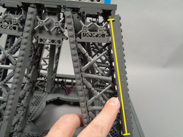
As shown in the first photo for this step, carefully pass the end of the second light strip through the outside of the pillar.
-
As shown in the second photo for this step, attach the second light strip (shown by the yellow line) and make sure it is firmly attached to the pillar.
-
-
-
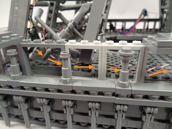
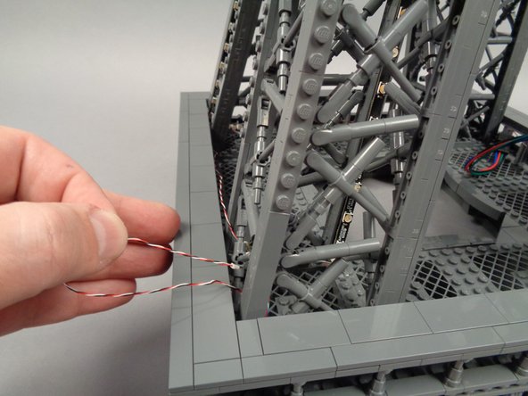
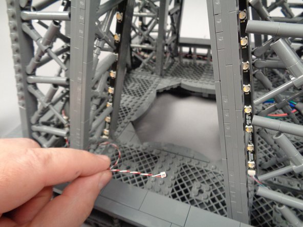
Tuck the adapter board into the base of the first pillar, then remove a section from the outer frame as shown in the first photo for this step.
-
As shown by the orange arrows in the second photo for this step, route the control wire coming from the OUTPUT plug on the adapter board behind the window frames.
-
Make sure the wire passes UNDER the "X" shaped frame at the base of the pillar, and BEHIND the window frames.
-
As shown in the third photo for this step, re-attach the section of frame you removed earlier.
-
-
-
Next, you will rotate your Eiffel tower in a clockwise direction-- this is the same direction the loose control cable from the previous step is pointing toward.
-
The illustration for this step shows the tower rotated so that pillar "A" (where you installed the first light strip pair) is to the left, and pillar "B" (where you will install the next strip pair) is in the center.
-
You can click on the image to enlarge it if needed.
-
To install the next light strip pair, you will repeat the same process as you used with the first.
-
-
-
As shown in the first photo for this step, find the loose control cable coming from the first adapter board and first set of light strips.
-
As shown by the blue circle in the second photo for this step, connect the end of the control cable coming from the first adapter board to the INPUT plug on the second adapter board.
-
-
-
As shown by the green arrow in the photo for this step, connect another 3-wire control cable to the OUTPUT plug on the adapter board.
-
Leave the other end of the control cable unconnected for now.
-
-
-
As shown by the red circle in the first photo for this step, remove the small piece that supports the horizontal walkway. This needs to be removed to make room for the light strip.
-
Save this piece-- you will use it later as a bracket to hold wires in place.
-
As shown in the second photo for this step, pass the end of the first light strip (the end with the connected plug) into the base of the second pillar.
-
Pass the rest of the light strip into the inside of the pillar. Do not mount the strip yet.
-
-
-
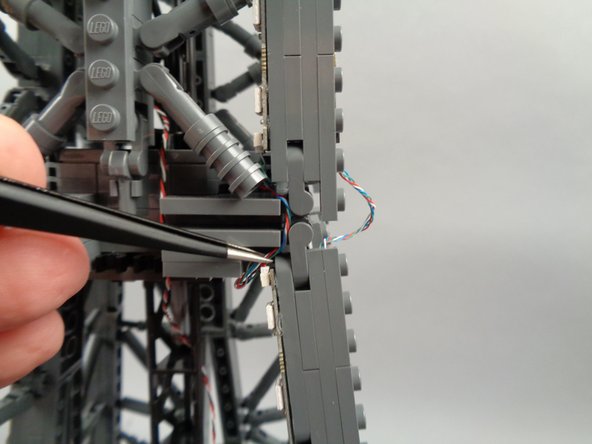
As shown in the first photo for this step, to make room for the control cable to pass, you need to temporarily disconnect the "X" crossbar at the bottom of the pillar.
-
As shown in the second photo, pass the incoming control cable BEHIND the "X" crossbar.
-
As shown in the third photo, re-attach the "X" crossbar with the control cable passing behind it.
-
-
-
Now you can finally attach the light strip to the inside rear of the pillar. As shown in the photo for this step, press with two fingers to make sure the light strip adheres firmly to the tower frame.
-
The blue line shows the light strip mounted on the inside of the pillar, facing outward.
-
-
-
As shown in the photos for this step, attach the next light strip (shown by the yellow line in the second photo) and make sure it is firmly attached to the pillar.
-
-
-
Tuck the adapter board into the base of the second pillar, then remove a section from the outer frame as shown in the first photo for this step.
-
As shown by the orange arrows in the second photo for this step, route the control wire coming from the OUTPUT plug on the adapter board behind the window frames.
-
Make sure the wire passes UNDER the "X" shaped frame at the base of the pillar, and BEHIND the window frames.
-
As shown in the third photo for this step, re-attach the section of frame you removed earlier.
-
-
-
Once again, rotate your tower middle section in a clockwise direction.
-
The illustration for this step shows the tower rotated so that pillar "B" (where you installed the last light strip pair) is to the left, and pillar "C" (where you will install the next strip pair) is in the center.
-
-
-
Take another light strip pair with connected adapter board and, as shown by the blue circle in the photo for this step, connect the end of the control cable coming from the second adapter board to the INPUT plug on the third adapter board.
-
-
-
As shown by the green arrow in the photo for this step, connect another 3-wire control cable to the OUTPUT plug on the adapter board.
-
Leave the other end of the control cable unconnected for now.
-
-
-
As shown in the first photo for this step, take the light strip connected to output #1 on the adapter board, and pass it through and into the center of the third pillar.
-
The yellow arrow in the first photo shows the small supporting piece for the horizontal walkway. You can leave this in place, but be careful when passing the light strip beneath it.
-
As shown in the second photo for this step, attach the light strip to the inside back of the third pillar facing you, pressing with two fingers to make sure it adheres firmly to the tower frame.
-
The blue line in the second photo shows the light strip installed.
-
-
-
As shown in the first photo for this step, pass the light strip connected to plug #2 on the adapter board into the center of the pillar.
-
As shown by the yellow arrow in the second photo, be careful of the small walkway support piece when passing the light strip into the center of the pillar.
-
If needed, you can temporarily remove this small piece to make it easier to pass the light strip into the center of the pillar, then re-attach it.
-
-
-
Turn the Tower slightly so you can access the adjacent side of the third pillar.
-
As shown by the red circle in the first photo for this step, remove the small piece that supports the horizontal walkway. This needs to be removed to make room for the light strip.
-
Save this piece-- you will use it later as a bracket to hold wires in place.
-
As shown in the second photo for this step, install the light strip you passed into the pillar before, pressing with two fingers to make sure it adheres firmly to the tower frame.
-
The yellow line in the second photo shows the light strip installed.
-
-
-
Tuck the adapter board into the base of the third pillar, then remove a section from the outer frame as shown in the first photo for this step.
-
As shown by the orange arrows in the second photo for this step, route the control wire coming from the OUTPUT plug on the adapter board behind the window frames.
-
Make sure the wire passes UNDER the "X" shaped frame at the base of the pillar, and BEHIND the window frames.
-
Re-attach the section of frame you removed earlier.
-
As shown in the third photo for this step, re-attach the section of frame you removed earlier. Your control wire should now reach over toward the fourth and final pillar.
-
-
-
Once again, rotate the middle section of your tower in a clockwise direction.
-
The illustration for this step shows the tower rotated so that pillar "C" (where you installed the last light strip pair) is to the left, and pillar "D" (where you will install the next strip pair) is on the right.
-
-
-
Take the final light strip pair with connected adapter board and, as shown by the blue circle in the photo for this step, connect the end of the control cable coming from the third adapter board to the INPUT plug on the fourth adapter board.
-
-
-
As shown by the green arrow in the photo for this step, connect another 3-wire control cable to the OUTPUT plug on the adapter board.
-
Leave the other end of the control cable unconnected for now.
-
-
-
As shown by the red circle in the photo for this step, remove the small piece that supports the horizontal walkway. This needs to be removed to make room for the light strip.
-
Save this piece-- you will use it later as a bracket to hold wires in place.
-
-
-
As shown in the first photo for this step, to make room for the control cable to pass, you need to temporarily disconnect the "X" crossbar at the bottom of the pillar.
-
As shown in the second photo, pass the incoming control cable BEHIND the "X" crossbar.
-
As shown in the third photo, re-attach the "X" crossbar with the control cable passing behind it.
-
-
-
As shown in the first photo for this step, peel the backs off of the sticky squares on the fourth pair of light strips, and pass the strip connected to plug #1 on the adapter board into the center of the pillar.
-
As shown in the second photo, mount the light strip to the rear inside of the pillar, pressing with two fingers to make sure it adheres firmly to the tower frame.
-
The blue line in the second photo shows the light strip mounted.
-
-
-
As shown in the first photo for this step, pass the end of the light strip attached to plug #2 of the adapter board into the center of the pillar.
-
As shown in the second photo for this step, mount the second strip, pressing with two fingers to make sure it adheres firmly to the tower frame.
-
The yellow line in the second photo shows the light strip mounted.
-
-
-
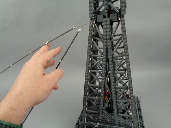
Next you will route the control cable connected to the fourth adapter board back toward the first pillar. There you will ultimately connect it to the inter-level connecting board.
-
As shown in the first two photos for this step, pass the control cable connected to the fourth adapter board through the center of the fourth pillar and back toward the first pillar.
-
As shown by the orange circle in the third photo, make sure the control cable can reach all the way into the center of the first pillar.
-
You won't connect the cable now-- you are just making sure it will reach. In case it does not reach, you can re-position the adapters inside the four pillars as needed to free up additional length for the fourth cable to reach into the first pillar.
-
-
-
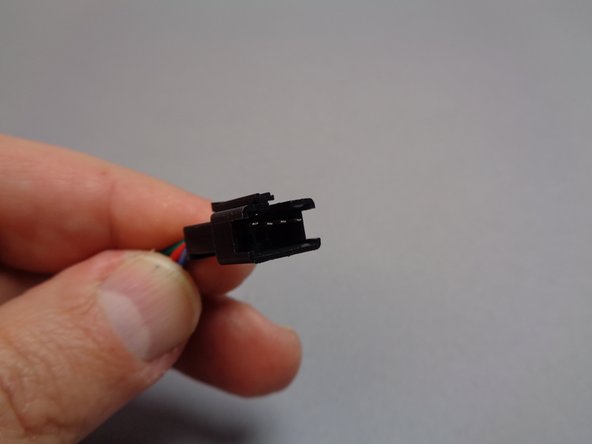
The inter-level connecting board has different plugs on each end. The first photo in this step shows the male plug, which is large and has a latching clip on top.
-
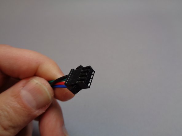
The second photo shows the female plug. This is the plug you will be feeding up toward the top tower section in the coming steps.
-
-
-
In order to complete the control loop for the middle section of your tower, you will need to place the inter-level connecting board inside the first pillar, so the control cable coming from the 4th pillar can reach.
-
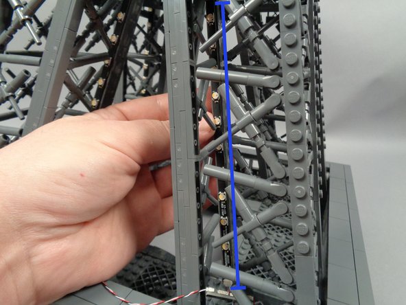
As shown by the green arrows in the first two photos for this step, feed the female plug of the inter-level connecting board into the center of pillar "A" of the tower middle section (this is the same pillar where you attached the first two light strips).
-
Continue feeding the female plug upward through the center of the pillar, until the board is inside the pillar and the female plug extends out near the top of the middle section as shown in the third photo.
-
-
-
Take the male plug of the inter-level connecting board, and as shown by the purple arrows in the second photo for this step, pass it inside the pillar and out the bottom right.
-
When you are done feeding the male plug, it should hang over the inner edge of the center Tower section as shown by the blue circle in the third photo.
-
-
-
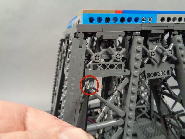
As shown in the photo for this step, remove the "X" crossbar on the outside of the first pillar to make room to connect the control cable.
-
-
-
As shown in the first photo for this step, pull the end of the control cable from the 4th adapter board toward the inter-level connecting board.
-
As shown by the green arrow in the second photo for this step, connect the control cable to the plug labeled END on the inter-level connecting board.
-
This connection will form a complete control loop for the light strips around the middle section.
-
Place the inter-level connecting board inside the first pillar with all cables connected.
-
As shown in the third photo, replace the "X" crossbar you removed earlier.
-
-
-
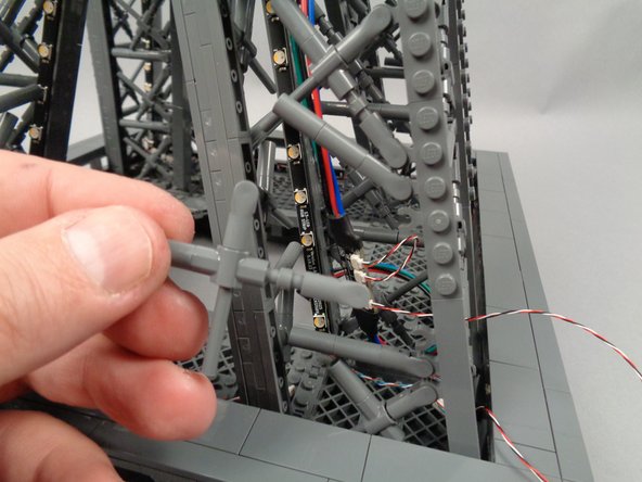
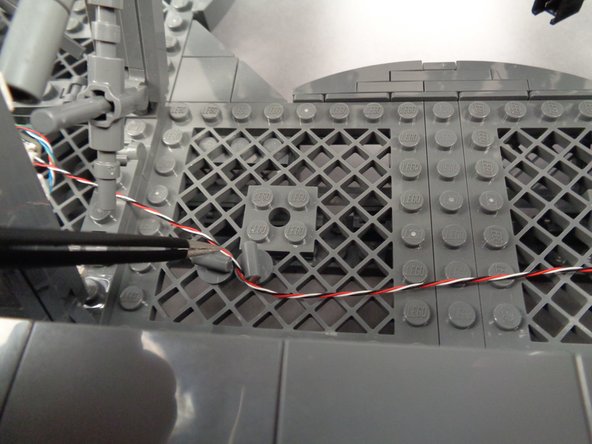
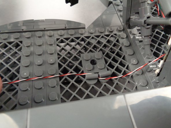
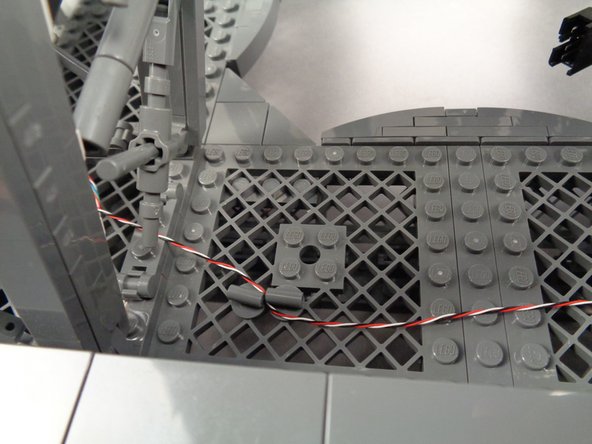
If any control wires are loose passing between any of the pillars, you can use the pieces you removed earlier to secure them as shown in the photos for this step.
-
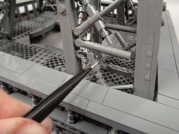
Insert two of the pieces into the large grid plates where you want to secure wires. To make it easier to insert wires, you can turn one of the parts sideways.
-
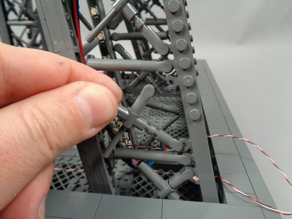
Pass the wire between the pieces, and rotate so they are parallel to hold the wire in place.
-
-
-
If there are any loose wires, you can tidy them up as shown in the photos by twisting, then tucking inside the nearest pillar.
-
-
-
Next, you will prepare to test the lights in the middle section.
-
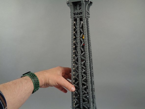
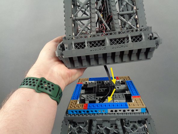
As shown in the first photo for this step, place your tower's middle section on top of the base section with the "A" pillars of both sections aligned. The green lines in the photo show the locations of the first pair of light strips for both levels-- these should be aligned.
-
As shown by the orange circle in the third photo, press the male plug of the inter-level connecting board into the female plug coming up from the main controller in the base level.
-
The plugs can require some force to connect-- press firmly but insert both plugs at a straight angle to avoid bending any pins inside the plugs. You will feel the top latch "click" when the plugs are fully connected.
-
ALWAYS DISCONNECT THESE PLUGS BEFORE MOVING YOUR TOWER OR SEPARATING SECTIONS!
-
-
-
Connect the USB-C power cable once again, and make sure the power switch is on and that the power supply is plugged into mains power.
-
-
-
The video in this step shows all 16 light strips in the lower and middle tower sections running different lighting effects.
-
When your power is on, you should see similar effects in your tower.
-
The specific patterns shown is not important-- what you are looking for is that all 16 light strips are active and showing colored lights.
-
If some light strips work, but not all, there is likely a connection problem somewhere in your control cable chain. Double check the plug connections on each adapter board and the connections to each light strip.
-
Something else to double-check if not all of your light strips are working: Look back at the diagram in Step 54 to make sure you have the INPUTs and OUTPUTs of each adapter board in the middle section connected correctly.
-
If there is a mix-up with any of these connections (two INPUTs or two OUTPUTs connected, for example), this will cause lights further down the chain to stop working. While this will not damage any lights, it will prevent the control signal from reaching all strips.
-
If lights in the lower section are working, but lights in the middle section are not working, you should check the connection between the main controller in the base section and the inter-level connecting board in the middle section.
-
If your Eiffel Tower lights are working as shown in the video, you can continue with installation and move to the top tower section.
-
-
-
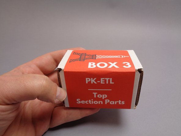
Next you will open the third and final box, Box 3.
-
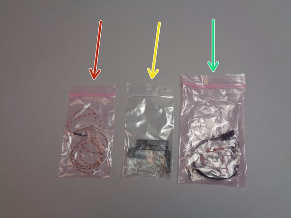
The arrows in the second photo for this step show the three bags included inside Box 3.
-
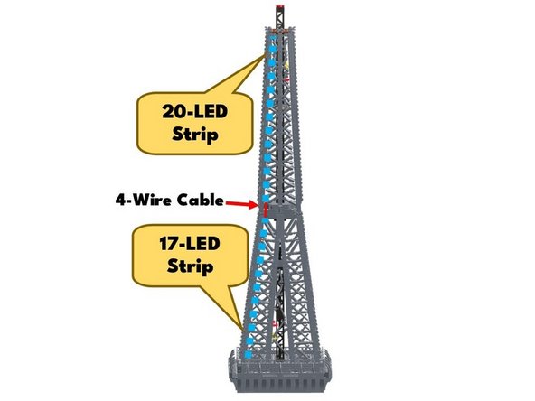
The red arrow shows the flexible LED light strip you will use in the top "broadcast tower" section of the Eiffel Tower.
-
The yellow arrow shows the LEGO parts you will use to modify the "broadcast tower" section to make room for the flexible light strip.
-
The green arrow shows the control cables, inter-level connecting board, and adapter boards you will use to connect the 16 light strips in the top tower section.
-
-
-
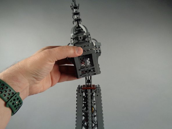
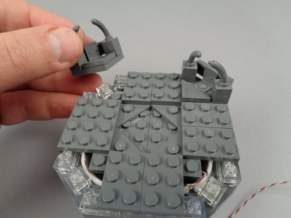
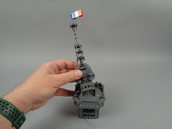
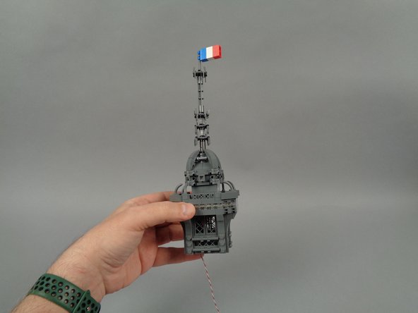
As shown in the photos for this step, remove the broadcast tower section from the top of your Eiffel Tower, and also remove the antenna assembly from the center of the tower top.
-
-
-
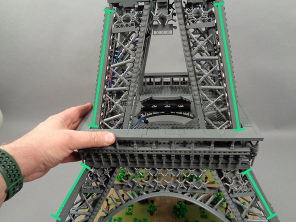
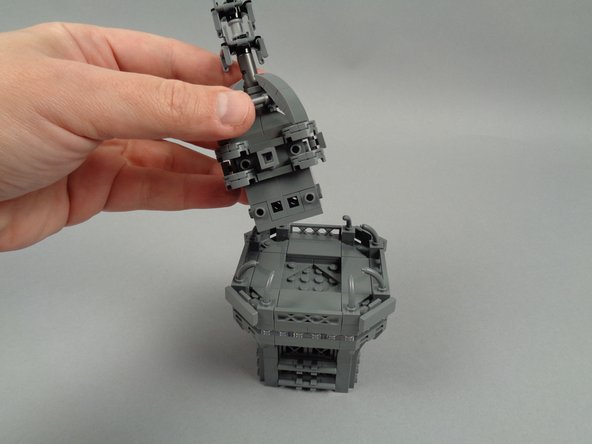
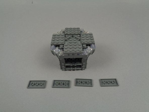
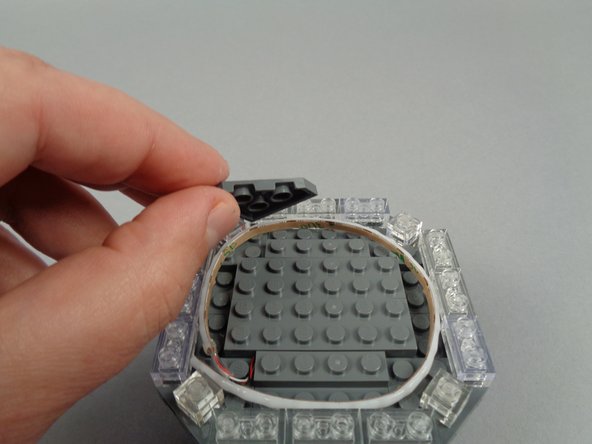
You will be raising the clear section of the broadcast tower by one plate height, to make room for the flexible LED strip.
-
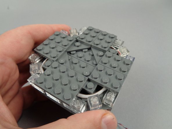
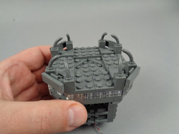
The photos for this step show the parts to begin removing from your broadcast tower to make room for the flexible light strip.
-
-
-
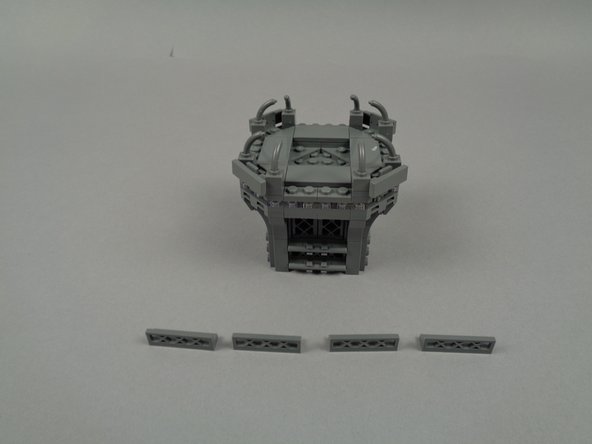
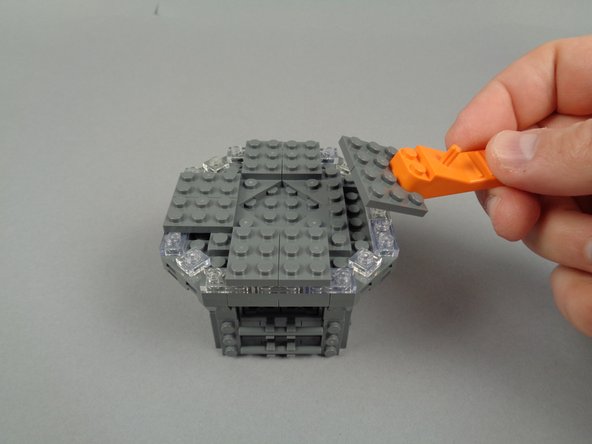
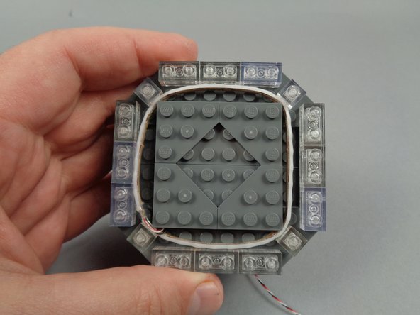
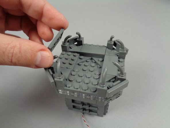
As shown in the photos for this step, continue disassembly by removing the eight 2x3 LEGO plates.
-
-
-
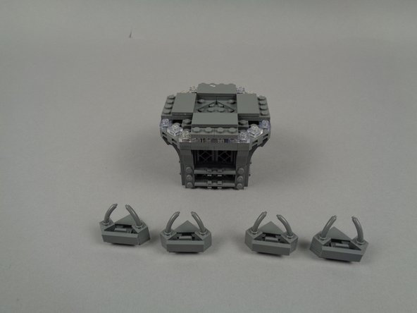
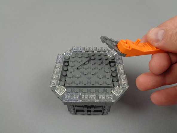
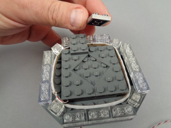
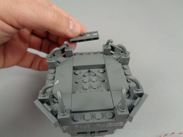
As shown in the photos for this step, continue disassembly by removing the four triangle/corner plates.
-
-
-
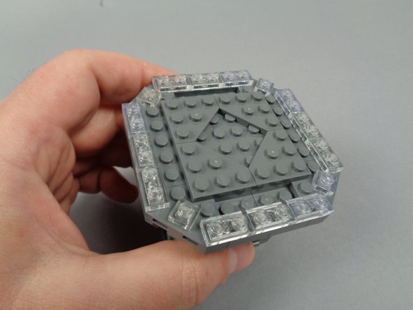
As shown in the photos for this step, remove the six clear 1x2 plates on either side of the top center.
-
-
-
As shown in the photos for this step, finish disassembly by removing the large center plate and windows beneath.
-
-
-
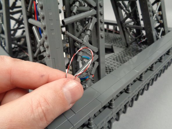
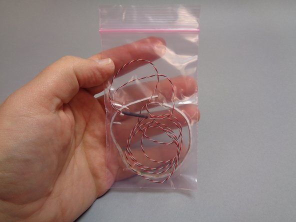
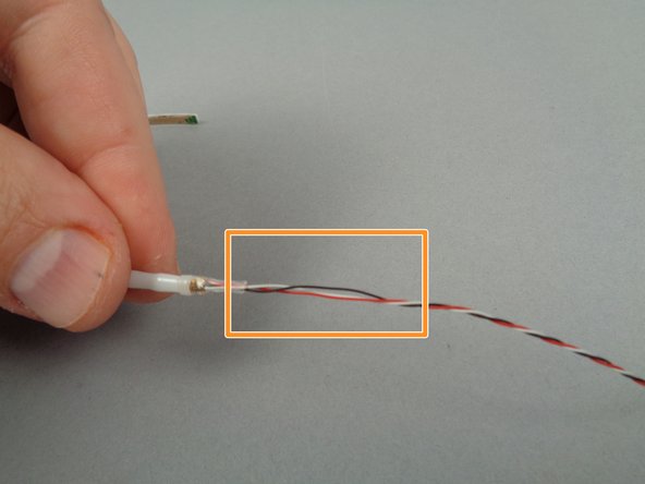
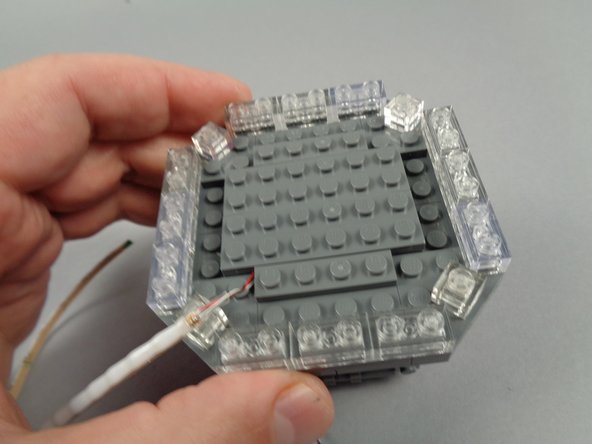
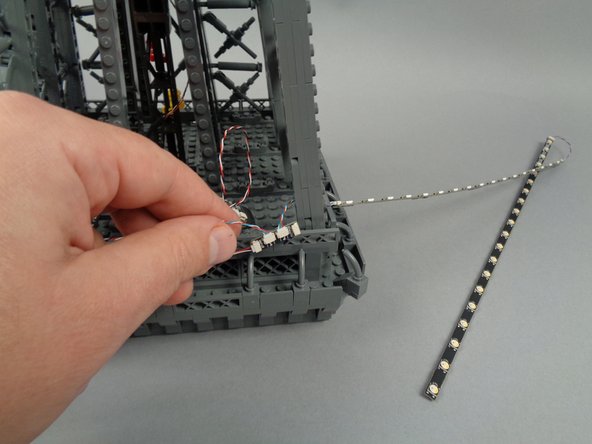
Remove the flexible LED light strip from its pink bag.
-
As shown by the orange box in the second photo for this step, carefully unwind the section of wire close to the end of the flexible strip. You can do this by holding the strip with one hand and carefully turning the wire with the other hand until a small section of wire becomes un-twisted.
-
Un-twisting the wire will help prevent it from being "pinched" when mounting inside the broadcast tower in the following steps.
-
-
-
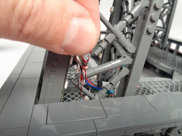
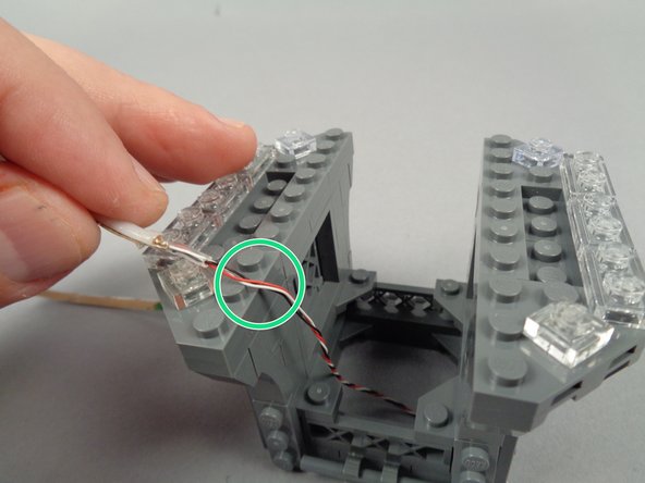
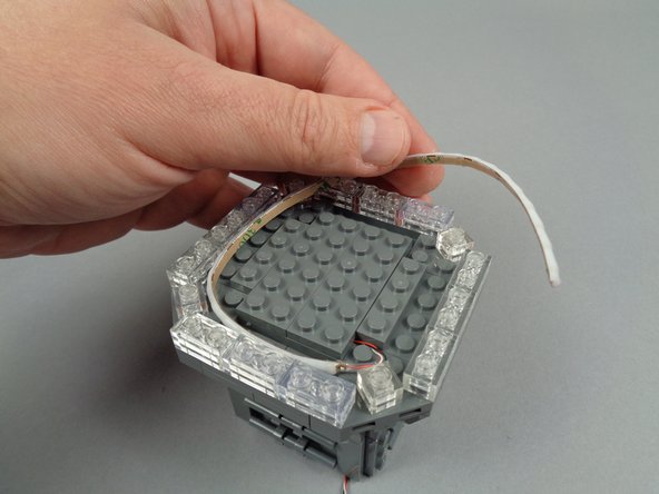
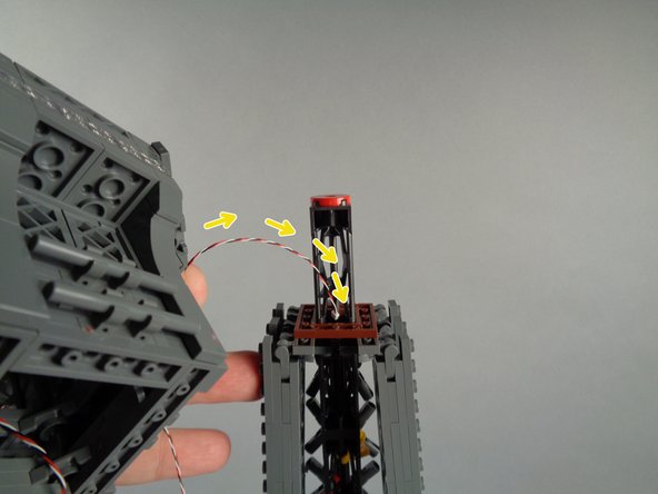
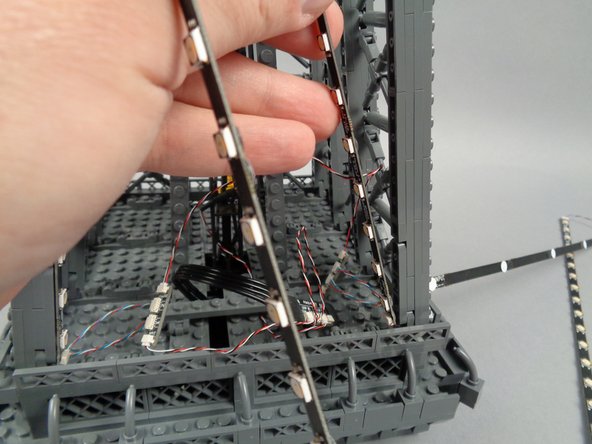
As shown by the orange arrows in the first photo for this step, pass the end of the flexible LED light strip wire down through the center of the broadcast tower.
-
Position the end of the strip so the un-twisted section of wire is at the top edge as shown by the green circle in the second photo for this step.
-
As shown by the third photo for this step, re-attach the center section of the broadcast tower, holding the wire in place for the flexible LED light strip.
-
-
-
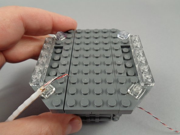
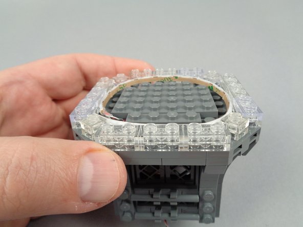
As shown in the photos for this step, re-attach the clear 1x2 LEGO plates you removed earlier.
-
-
-
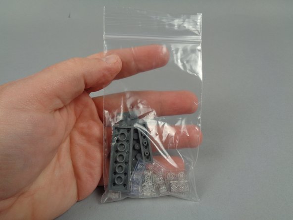
Open the bag of LEGO parts that was included in your Box 3.
-
-
-
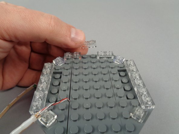
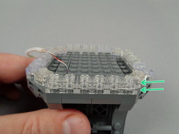
As shown in the photos for this step, use the clear LEGO plates inside the parts bag to extend the clear section of the broadcast tower by one plate height.
-
The green arrow in the third photo for this step shows the finished clear section, extending around the edge of the broadcast tower, now two plates in height.
-
-
-
As shown in the photos for this step, use the remaining LEGO plates from the parts bag to extend the height of the center section of the broadcast tower by one plate.
-
When you are finished, the top of your broadcast tower should look like the third photo.
-
Be careful when attaching plates not to pinch any wires of the flexible LED light strip. Wires should pass between, not on top of, studs.
-
-
-
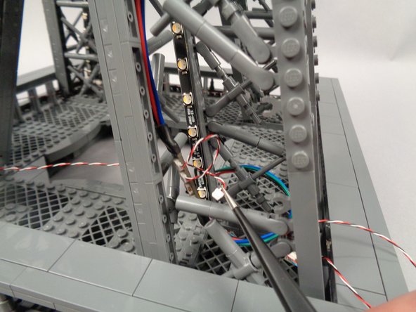
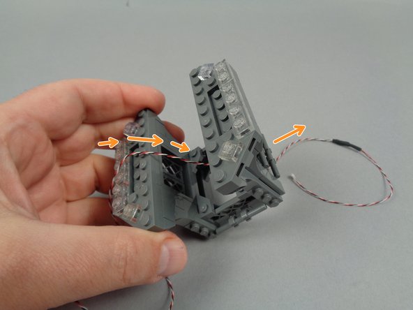
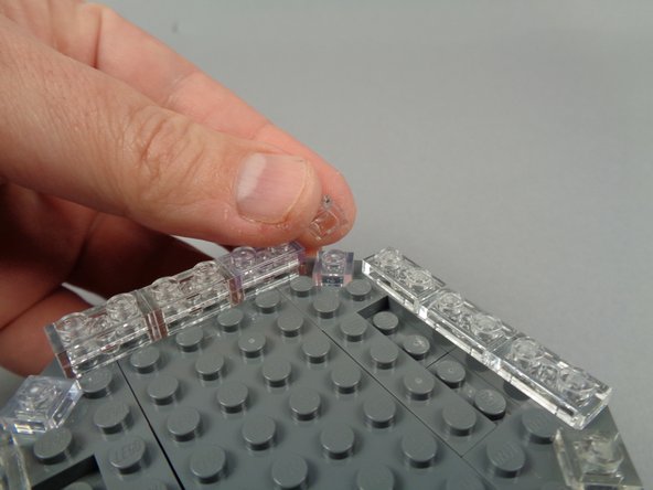
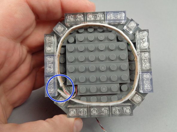
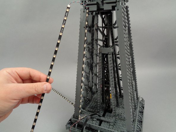
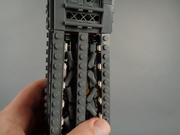
As shown in the photos for this step, take the flexible LED light strip and wrap it around the channel in the broadcast tower, behind the clear plates.
-
Make a complete circle running once around the tower as shown in the second photo.
-
As shown by the blue circle in the third photo, the end of the strip should be positioned at the same location in the circle as the beginning of the strip.
-
As shown in the third photo for this step, the flexible LED strip should sit inside the channel without sticking above any plates.
-
-
-
Begin re-assembling the broadcast tower by replacing the triangle/corner LEGO plates as shown in the photos for this step.
-
-
-
As shown in the photos for this step, continue re-assembling the broadcast tower with the eight 2x3 LEGO plates you removed earlier.
-
-
-
Continue re-assembly by attaching the four corner sections you removed earlier.
-
Make sure the corner section pieces do not pinch any wires or crush the flexible LED light strip beneath.
-
-
-
Finish re-assembling your broadcast tower by re-attaching the 2x4 LEGO tiles and fence pieces as shown in the first two photos for this step.
-
When you are finished, your broadcast tower should look like the third photo.
-
-
-
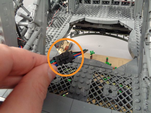
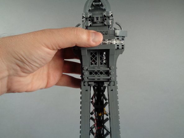
As shown in the first photo for this step, re-attach the center antenna section.
-
Your broadcast tower should now look like the second photo for this step.
-
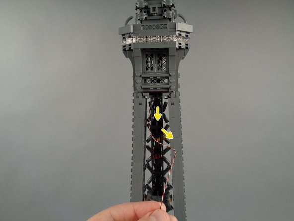
As shown in the third photo, you should have the control wire for the flexible LED light strip coming out of the bottom center of the tower.
-
Set the broadcast tower assembly aside for now. You will connect it in a future step.
-
-
-
The first photo for this step shows the bag of connecting parts included in your Box 3.
-
The second photo shows the parts in detail.
-
The green box shows the 16 short 4-wire cables you will use to connect the light strips.
-
The yellow box shows the four adapter boards you will use to create a chain connecting all light strips on this level.
-
The blue box shows the 3-wire cables you will use to connect the adapter boards in a loop with the inter-level connecting board.
-
The purple arrow shows the inter-level connecting board for the top section.
-
-
-
For the top section of your Eiffel Tower, you will use the remaining two bags of light strips (eight strips in each bag).
-
Carefully open these two bags.
-
Do not tear these bags open-- use a pair of scissors to cut the top open, taking care to avoid cutting any light strips or LED lights.
-
-
-
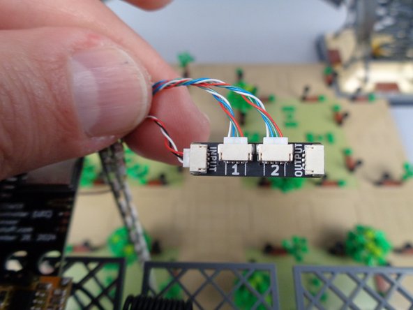
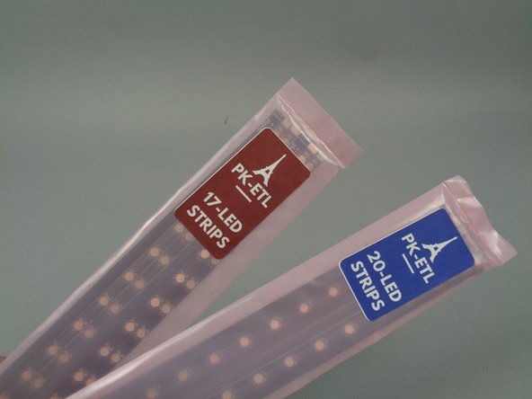
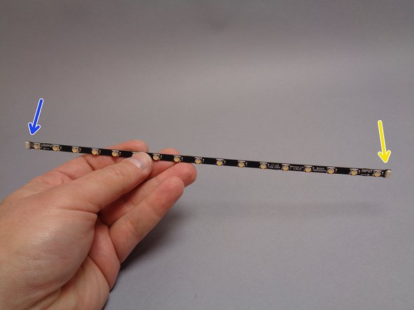
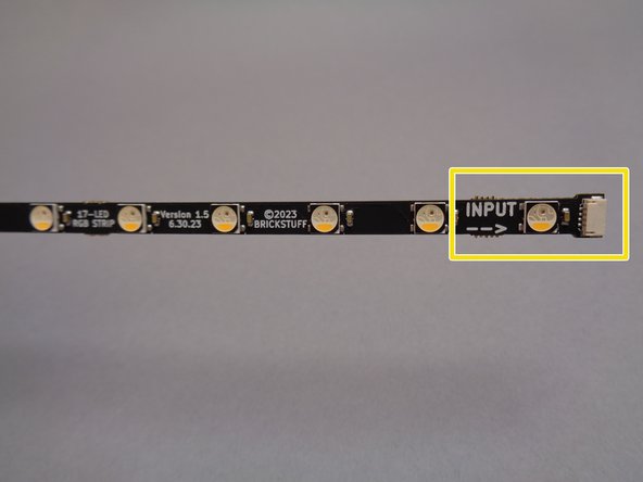
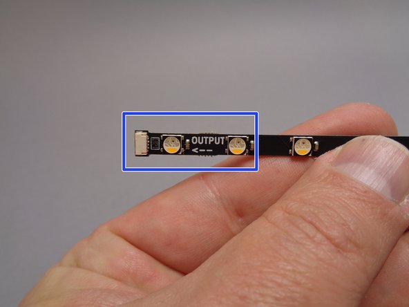
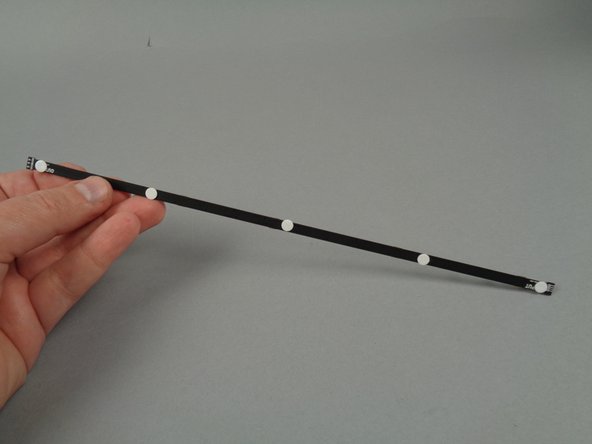
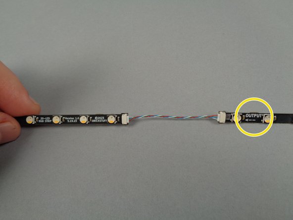
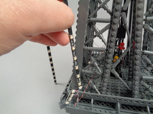
The photos in this step show the 17-LED light strips in greater detail.
-
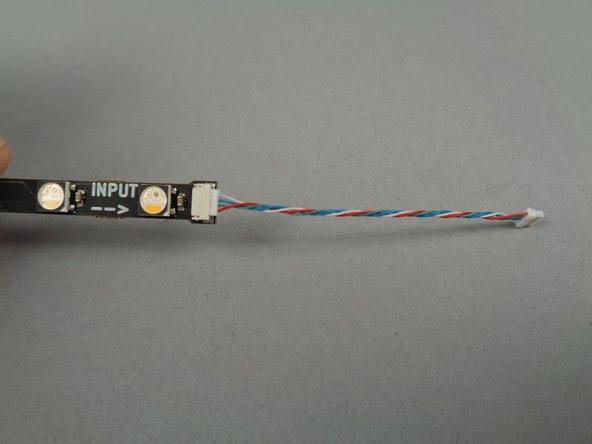
As shown by the yellow and blue arrows in the first photo, the 17-LED strips have plugs on both ends.
-
The yellow arrow in the first photo and the yellow box in the second photo show the INPUT connector for the strips.
-
The blue arrow in the first photo and the blue box in the second photo show the OUTPUT connector for the strips.
-
You will use the OUTPUT connector to connect to the 20-LED light strips.
-
-
-
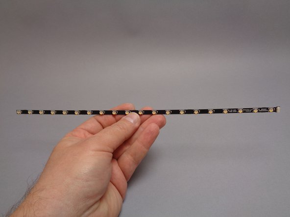
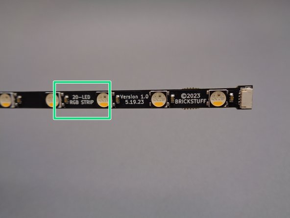
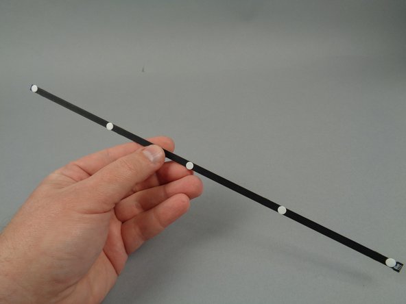
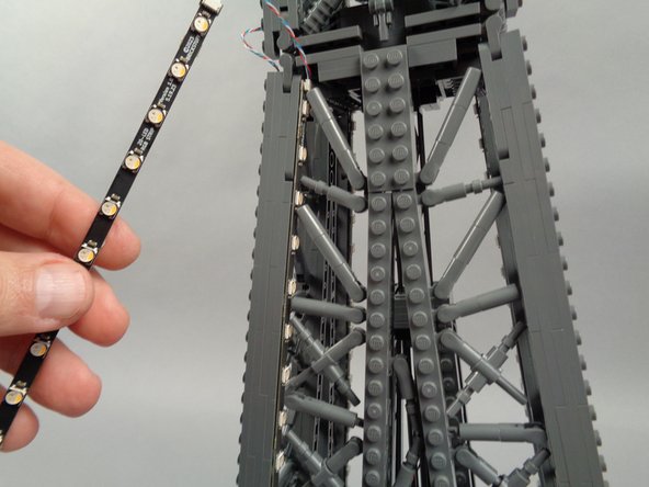
The first photo for this step shows the 20-LED light strip.
-
You can identify which type of light strip you're working with by looking at the end with the connecting plug (or, for the 17-LED strips, the INPUT connector end), as shown by the green box in the second photo.
-
-
-
For the top section of your Eiffel Tower, light strips will be connected together in addition to being connected to adapter boards. This is why there are twice as many 4-wire cables in Box 3 as in the other boxes (16 instead of eight).
-
As shown in the illustration for this step, you will connect 17-LED strips and 20-LED strips together for each lighting segment.
-
-
-
As shown in the photos for this step, attach sticky dots to the backs of the eight 17-LED strips and the eight 20-LED strips.
-
Use five sticky dots per strip as shown.
-
-
-
As shown in the photos for this step, connect 4-wires cables to both ends of the 17-LED light strips.
-
You will use up all of the 4-wire cables in Box 3, using a total of 16 for the eight 17-LED strips.
-
-
-
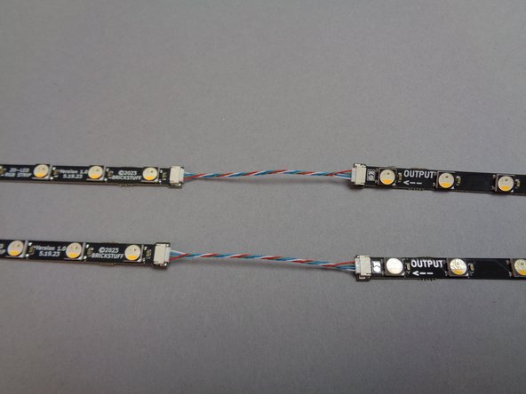
As shown in the photos for this step, connect the 17-LED strips and the 20-LED strips together at the OUTPUT end of the 17-LED strips.
-
As shown by the yellow circle in the first photo, make sure you are connecting the OUTPUT end of the 17-LED strips to the 20-LED strips.
-
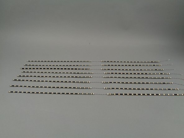
When you are finished connecting strips, you should have eight sets as shown in the third photo for this step.
-
-
-
As shown in the photos for this step, connect the light strips in pairs to plugs #1 and #2 on the adapter boards.
-
As shown by the green arrows in the first photo, make sure you are connecting the ends of the 17-LED strips labeled INPUT to the adapter boards.
-
-
-
The installation process for the top level light strips is the same as with the other two levels: you will use control cables and adapter boards to connect the light strips in a loop around the top level, beginning and ending at the inter-level connecting board.
-
The blue line in the illustration for this step also shows where you will connect the control wire from the broadcast tower to the inter-level connecting board.
-
-
-
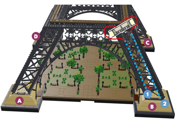
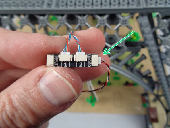
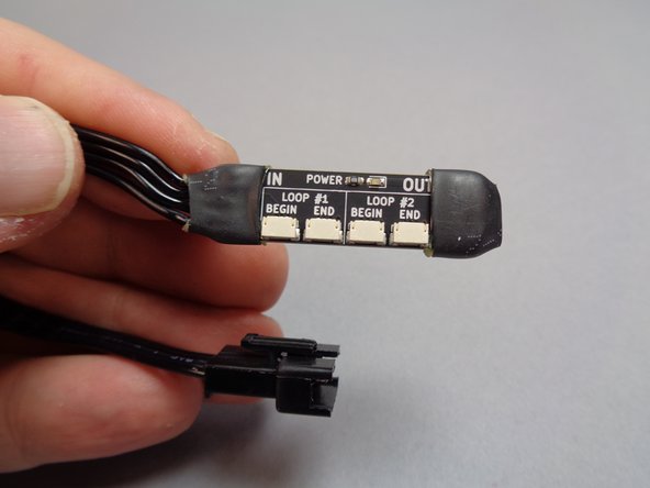
The photo for this step shows the inter-level connecting board for the top Eiffel Tower section. This board is different from the middle-level board in several ways:
-
There is a wire connected to only one end of the board (the IN end).
-
There is no looping wire connecting the "LOOP #2" plugs.
-
-
-
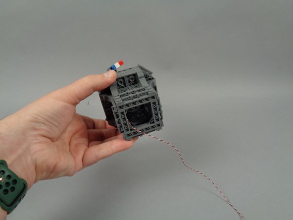
Position the top section of your Eiffel Tower as shown in the photos for this step, with the small elevator cars inside the structure facing away from you.
-
The red and yellow arrows in the second photo show the tower positioned with the two elevator cars facing away from the camera.
-
-
-
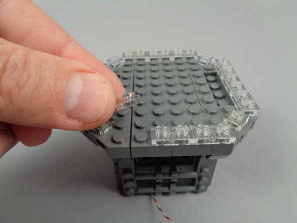
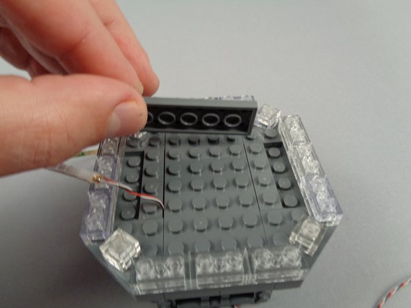
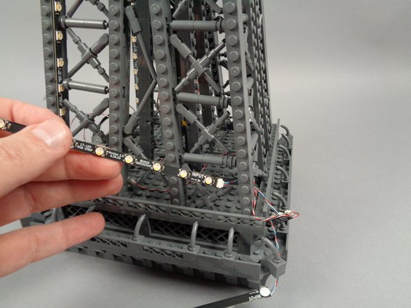
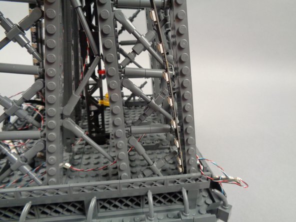
Next you will remove the lower panel of your top tower section, to make room for mounting the inter-level connecting board and the first pair of light strips.
-
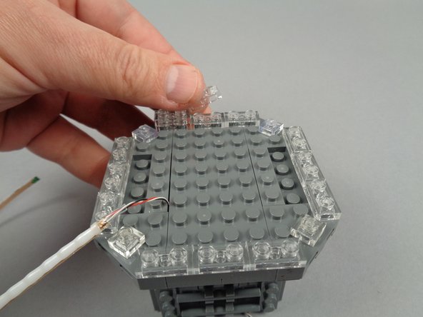
As shown by the green arrow in the first photo for this step, begin by removing the 2x4 LEGO plate at the top center of the lower panel.
-
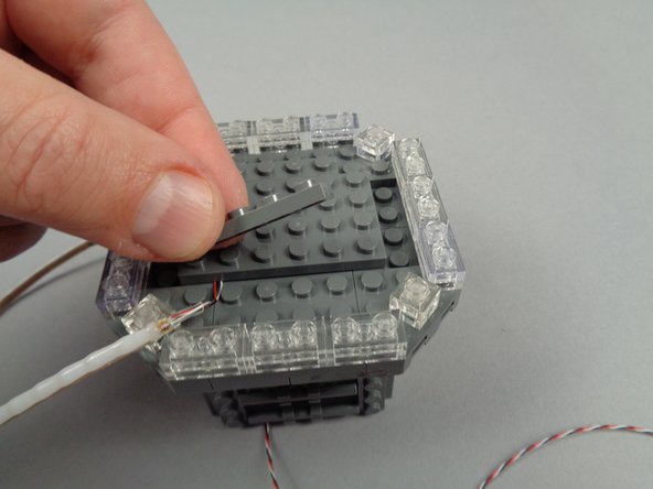
As shown in the second and third photos, use the tweezers to remove the two clips holding the top of the panel in place, then gently ease the panel toward you.
-
-
-
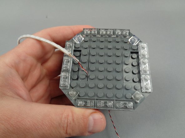
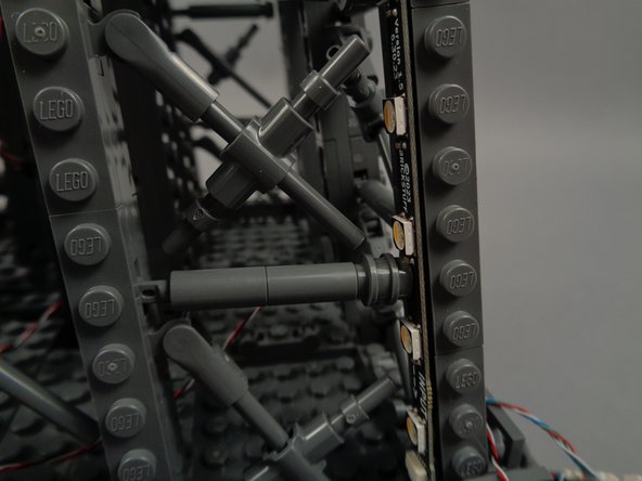
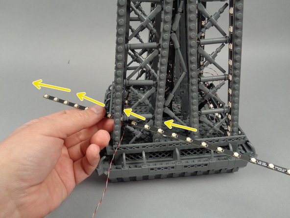
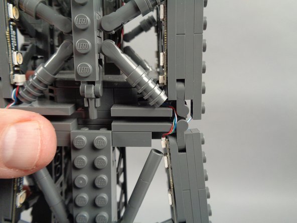
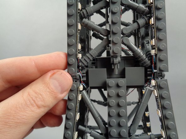
Finish removing the rear panel by pressing down with the tweezers on the left and right side base (red circle in the first and second photos) while pulling up on the rear panel (yellow arrows in both photos).
-
As shown in the third photo for this step, you should now be able to fully remove the rear panel.
-
-
-
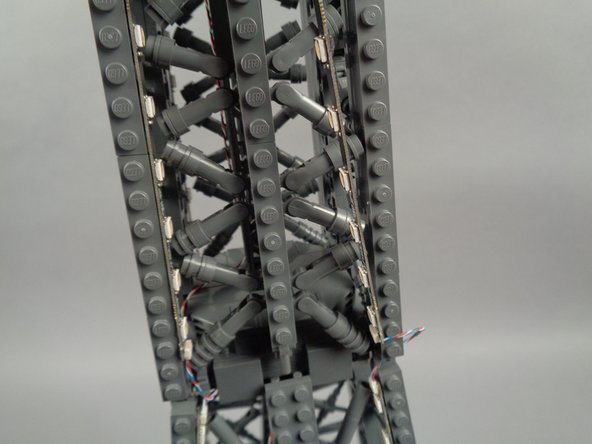
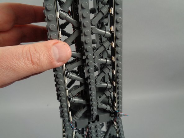
As shown in the photo for this step, you should now have clear access to the lower rear of the top tower section.
-
-
-
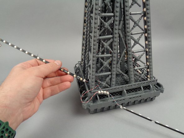
As shown in the first photo for this step, carefully tilt the top tower section, and press upward with your fingers to loosen the 2x8 LEGO plate at the base.
-
Remove the 2x8 plate as shown in the second photo.
-
As shown in the third photo for this step, also remove the 1x8 plate in the base.
-
-
-
As shown by the yellow arrows in the first photo for this step, pass the large plug of the inter-level connecting board down through the opening you made by removing the two plates.
-
As shown by the green box in the second photo, re-attach the 2x8 plate.
-
Your setup should now look like the third photo, with the plug for the inter-level connecting board passing down through the bottom of the top tower section.
-
-
-
As shown in the photos for this step, replace the 1x8 plate you removed earlier, placing it sideways to hold the wire for the inter-level connecting board.
-
-
-
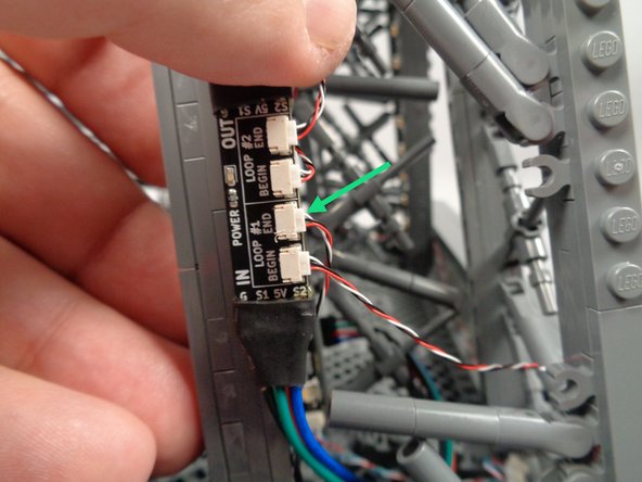
As shown by the green arrow in the first photo for this step, take one of the control cables and connect one end to the plug labeled "BEGIN" in the "LOOP #1" section of the inter-level connecting board.
-
Make sure you connect the wire to the exact plug shown.
-
Pick one of the light strip pairs to be the first for this section, and connect the other end of the control cable to the INPUT plug on the adapter board as shown by the blue circle in the second photo.
-
-
-
As shown in the illustration for this step, you will position the light strips connected to the #1 plug on the adapter board on the left side of each tower pillar, and the light strips connected to the #2 plug on the adapter board to the right side of each pillar.
-
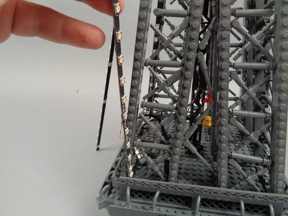
As shown in the second and third photos for this step, take the light strips connected to plug #1 on the adapter board and pass them through the first tower pillar.
-
-
-
Remove the backs of the sticky dots on the second light strip (connected to plug #2 of the adapter board), and attach the strip to the tower frame as shown in the photos for this step.
-
Leave the top LED strip section (the 20-LED strip) hanging loose for now as shown in the second photo).
-
-
-
Remove the backs of the sticky dots on the first light strip (connected to plug #1 of the adapter board), and attach the strip to the tower frame as shown in the photos for this step.
-
Leave the top LED strip section (the 20-LED strip) hanging loose for now as shown in the second photo).
-
-
-
As shown in the photos for this step, you will need to adjust cross-brace elements in the tower frame to make room for the LEDs and strips to fit.
-
-
-
As shown in the photos for this step, next you will remove the top rear panel section above where you removed the lower rear section earlier.
-
-
-
The rear section of your Eiffel Tower top should now be fully open, as shown in the photo for this step.
-
-
-
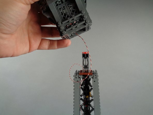
As shown by the yellow arrows in the first photo for this step, pass the control cable for the broadcast tower down through the center of the tower top, inside of the brown square plate.
-
Pull the wire down into the center of the top tower section as you finish re-attaching the broadcast tower section.
-
-
-
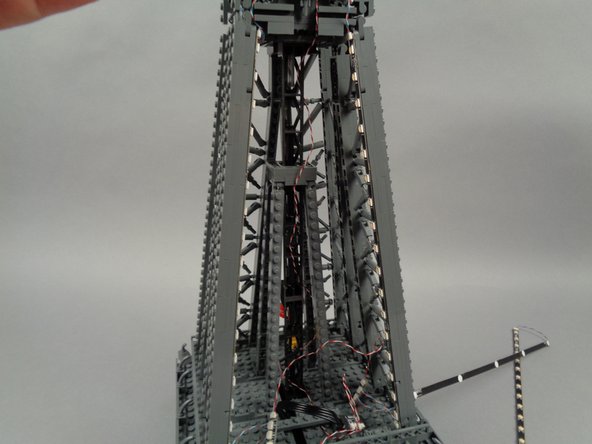
As shown by the yellow arrows in the photos for this step, carefully wind the control wire for the broadcast tower lights down through the center of the top tower section, looping the wire several times through the center black support pillars.
-
As shown in the third photo, the wire should be just long enough to reach the bottom of the top section.
-
-
-
As shown by the green arrows in the first photo for this step, loop the control wire underneath the 1x8 support plate.
-
As shown by the purple circle in the second photo for this step, connect the control wire to the "BEGIN" plug in the "LOOP #2" section of the inter-level connecting board.
-
You will leave the "END" plug in the "LOOP #2" section unconnected.
-
-
-
As shown in the photos for this step, re-attach the top rear tower frame section.
-
-
-
As shown in the photos for this step, next you will attach the top section (the 20-LED strip section) of light strip #2 to the inside of the tower frame.
-
As shown in the second and third photos, because of the limited extra space at this level of the tower, you will need to re-position some brace elements in order to make room for the LED lights and the strip.
-
Go slowly, and re-position elements as needed. In cases where brace elements have multiple round plates attached, you can remove one or more of these extra parts to make the brace elements shorter and to make more room for the light strip.
-
-
-
Next you will attach the top section of light strip #1 as shown in the photos for this step.
-
Remember to move slowly and to re-position brace elements as needed to make room for the LED lights and strip.
-
-
-
As shown in the photos for this step, you can use the tweezers to tidy up any visible sections of wire connecting the 17-LED sections and 20-LED sections of both light strips.
-
-
-
Take another 3-wire control cable, and as shown by the green arrow in the first photo for this step, connect one end of it to the OUTPUT plug on the adapter board for the pair of light strips you just finished mounting.
-
Select another light strip pair and adapter board, and connect the other end of the control cable to the INPUT plug on the next adapter board.
-
-
-
The illustration for this step shows how you will mount the next light strip pair. The positioning of each strip will be the same as with the pervious pair:
-
The strips connected to plug #1 on the adapter board will attach to the left side of the pillar as shown in the illustration.
-
The strips connected to plug #2 on the adapter board will attach to the right side of the pillar as shown in the illustration.
-
-
-
As shown in the first photo for this step, you will begin with the LED light strips connected to plug #2 on the adapter board.
-
To prepare, feed the strips connected to plug #2 on the adapter board through the center of the next pillar as shown by the yellow arrows in the second photo.
-
Continue passing the strips through the pillar until both the 17-LED strip and the 20-LED strip are through, as shown in the third photo.
-
To make it easier to pass the strips through, you can fold them in half at the middle cable and pass together as a set.
-
-
-
Remove the backs of the sticky dots on the first light strip (connected to plug #1 of the adapter board), and attach the strip to the tower frame as shown in the photos for this step.
-
Leave the top LED strip section (the 20-LED strip) hanging loose for now as shown in the second photo).
-
-
-
Remove the backs of the sticky dots on the second light strip (connected to plug #2 of the adapter board), and attach the strip to the tower frame as shown in the photos for this step.
-
-
-
As shown in the photo for this step, you should now have both lower strips (the 17-LED strips) attached and the two upper strips (the 20-LED strips) hanging loose.
-
-
-
As shown in the photos for this step, attach the top of strip #1 to the tower frame, and re-position brace elements as needed to make room for the LED lights and strip.
-
-
-
As shown in the photos for this step, attach the top of strip #2 to the tower frame, and re-position brace elements as needed to make room for the LED lights and strip.
-
-
-
As shown in the photos for this step, you can use the tweezers to tidy up any visible sections of wire connecting the 17-LED sections and 20-LED sections of both light strips.
-
-
-
Take another 3-wire control cable, and as shown by the green arrow in the first photo for this step, connect one end of it to the OUTPUT plug on the adapter board for the pair of light strips you just finished mounting.
-
As shown by the yellow arrows in the second photo for this step, pass the other end of the control cable through the center of the tower toward the next pillar.
-
As shown in the third photo for this step, pull the end of the control cable through the next pillar. This will make it easier to connect the next adapter board.
-
-
-
As shown by the blue circle in the photo for this step, select another light strip pair and adapter board, and connect the other end of the control cable to the INPUT plug on the next adapter board.
-
-
-
The illustration for this step shows how you will mount the next light strip pair. The positioning of each strip will be the same as with the pervious pair:
-
The strips connected to plug #1 on the adapter board will attach to the left side of the pillar as shown in the illustration.
-
The strips connected to plug #2 on the adapter board will attach to the right side of the pillar as shown in the illustration.
-
-
-
As shown in the first photo for this step, you will begin with the LED light strips connected to plug #1 on the adapter board.
-
To prepare, feed the strips connected to plug #1 on the adapter board through the center of the pillar as shown by the yellow arrows in the second photo.
-
Continue passing the strips through the pillar until both the 17-LED strip and the 20-LED strip are through, as shown in the third photo.
-
To make it easier to pass the strips through, you can fold them in half at the middle cable and pass together as a set.
-
-
-
Remove the backs of the sticky dots on the first light strip (connected to plug #1 of the adapter board), and attach the strip to the tower frame as shown in the photos for this step.
-
Remember you can re-position elements as needed to make space for the lights. In cases where brace elements have multiple round plates attached, you can remove one or more of these extra parts to make the brace elements shorter and to make more room for the light strip.
-
-
-
Next you will mount the top section (the 20-LED section) of strip #1.
-
As shown in the photos for this step, attach the top of strip #1 to the tower frame, and re-position brace elements as needed to make room for the LED lights and strip.
-
-
-
Remove the backs of the sticky dots on the second light strip (connected to plug #2 of the adapter board), and attach the strip to the tower frame as shown in the photos for this step.
-
-
-
As shown in the photos for this step, attach the top of strip #2 to the tower frame, and re-position brace elements as needed to make room for the LED lights and strip.
-
-
-
As shown in the photos for this step, you can use the tweezers to tidy up any visible sections of wire connecting the 17-LED sections and 20-LED sections of both light strips.
-
-
-
Take another 3-wire control cable, and as shown by the green arrow in the first photo for this step, connect one end of it to the OUTPUT plug on the adapter board for the pair of light strips you just finished mounting.
-
As shown by the yellow arrows in the second photo for this step, pass the other end of the control cable into the center of the top tower section and over toward the fourth and final pillar.
-
As shown in the third photo for this step, pull the end of the control cable out through the pillar.
-
-
-
As shown by the blue circle in the photo for this step, take the last light strip pair and adapter board, and connect the other end of the control cable to the INPUT plug on the next adapter board.
-
-
-
The illustration for this step shows how you will mount the final light strip pair. The positioning of each strip will be the same as with the pervious pair:
-
The strips connected to plug #1 on the adapter board will attach to the left side of the pillar as shown in the illustration.
-
The strips connected to plug #2 on the adapter board will attach to the right side of the pillar as shown in the illustration.
-
-
-
As shown in the first photo for this step, you will begin with the LED light strips connected to plug #1 on the adapter board.
-
To prepare, feed the strips connected to plug #1 on the adapter board through the center of the next pillar as shown by the yellow arrows in the second photo.
-
Continue passing the strips through the pillar until both the 17-LED strip and the 20-LED strip are through, as shown in the third photo.
-
To make it easier to pass the strips through, you can fold them in half at the middle cable and pass together as a set.
-
-
-
Remove the backs of the sticky dots on the first light strip (connected to plug #1 of the adapter board), and attach the strip to the tower frame as shown in the photos for this step.
-
Leave the top LED strip section (the 20-LED strip) hanging loose for now as shown in the second photo).
-
-
-
Remove the backs of the sticky dots on the second light strip (connected to plug #2 of the adapter board), and attach the strip to the tower frame as shown in the photos for this step.
-
-
-
As shown in the photos for this step, attach the top of strip #1 to the tower frame, and re-position brace elements as needed to make room for the LED lights and strip.
-
-
-
As shown in the photos for this step, attach the top of strip #2 to the tower frame, and re-position brace elements as needed to make room for the LED lights and strip.
-
-
-
As shown in the photos for this step, you can use the tweezers to tidy up any visible sections of wire connecting the 17-LED sections and 20-LED sections of both light strips.
-
-
-
As shown by the green arrow in the photo for this step, connect the final 3-wire control cable to the OUTPUT plug on the adapter board.
-
As shown by the yellow arrows in the second photo for this step, pass the control cable through into the center of the tower, and back toward the inter-level connecting board where your loop began.
-
As shown in the third photo for this step, your wire should reach back to where you started with this level: the open rear section of the tower top.
-
-
-
As shown by the yellow arrow in the photo for this step, connect the control cable to the "END" plug in the "LOOP #1" section of the inter-level connecting board.
-
Before proceeding, make sure you have three plugs connected to the inter-level connecting board as shown:
-
Loop #1 BEGIN: this is where your wire loop for the top level should begin.
-
Loop #1 END: this is where your wire loop for the top level ends (this is the plug you just connected).
-
Loop #2 BEGIN: this is where the flexible LED light strip in the broadcast tower should connect.
-
Loop #2 END: this plug should be OPEN (not connected).
-
-
-
As shown in the photo for this step, you can now tidy up any loose wires in the top section by twisting them together in a bunch.
-
-
-
As shown in the photos for this step, you can now re-attach the rear top tower panel.
-
As shown by the yellow arrow in the first photo for this step, press down to clip both legs back into place.
-
As shown in the second photo, re-position any brace elements as needed to make room for LED lights.
-
As shown by the blue rectangle in the third photo, snap the top of the frame back into place, and re-attach the 2x4 LEGO plate to secure it.
-
-
-
As shown in the photo for this step, your upper Eiffel Tower section should now be re-assembled and complete.
-
You should also have the wire and plug visible extending out the bottom of the top section as shown.
-
-
-
You are now ready for the third and final test of your Eiffel Tower lighting.
-
As shown by the yellow arrows in the first photo for this step, carefully place the top tower section on top of the middle section, being careful to pass the wire and plug through the gap in the middle rear tower frame.
-
As shown in the second photo, you should now have the male plug (from the top section) and the female plug (from the middle section) accessible and able to reach.
-
As shown by the orange circle in the third photo, press the male plug into the female plug.
-
The plugs can require some force to connect-- press firmly but insert both plugs at a straight angle to avoid bending any pins inside the plugs. You will feel the top latch "click" when the plugs are fully connected.
-
ALWAYS DISCONNECT THESE PLUGS BEFORE MOVING YOUR TOWER OR SEPARATING SECTIONS!
-
-
-
Connect your USB-C power cable, and make sure the power switch is on and the USB power supply is connected to mains power.
-
-
-
The video in this step shows all light strips in all three tower levels running different lighting effects.
-
When your power is on, you should see similar effects in your tower.
-
You should also see a rotating light effect at the top of your tower, inside the broadcast tower. If you do not see any lights in the broadcast tower, try pressing the "D" button on your remote control one time.
-
The specific patterns shown is not important-- what you are looking for is that all light strips are active on all levels and showing colored lights.
-
If some light strips work, but not all, there is likely a connection problem somewhere in your control cable chain. Double check the plug connections on each adapter board and the connections to each light strip.
-
Something else to double-check if not all of your light strips are working: Look back at the diagram in Step 114 to make sure you have the INPUTs and OUTPUTs of each adapter board connected correctly.
-
If there is a mix-up with any of these connections (two INPUTs or two OUTPUTs connected, for example), this will cause lights further down the chain to stop working. While this will not damage any lights, it will prevent the control signal from reaching all strips.
-
If lights in the lower and middle sections are working, but lights in the upper section are not working, you should check the connection between the inter-level connecting boards in both sections.
-
-
-
If all lights are working and running color patterns, and if you have lights in the broadcast tower section on top of your tower, then congratulations! Your installation was a success.
-
If you purchased the street lamp add-on kit along with your Eiffel Tower light kit, you can now proceed to the guide for installing that add on.
-
You can find out how to control and customize your lights by reading our Control Guide.
-
If you have any trouble with any lights in your setup:
-
Go back and review the suggested troubleshooting steps listed in the step for each of the three lighting tests.
-
Make sure you are using the USB-C power supply provided with your Brickstuff kit. We cannot provide support for your kit if you are using another power supply.
-
If you continue to have trouble, contact us at support(at)brickstuff.com and we'll do whatever we can to get you up and running.
-
THANK YOU from all of us at Brickstuff for your support of our work. We hope you enjoy your Eiffel Tower lights for many years to come!
-