
Introduction
This guide describes the steps for installing, configuring, and using the Brickstuff Premium Light and Sound kit for the LEGO Creator Expert Haunted House (#10273).
Tools
No tools specified.
Parts
Featured Document
-
-
There are several ways to read this guide:
-
Reading it on the web in your browser.
-
Downloading a PDF copy of the guide. You can do this by selecting "Download PDF" as shown by the red rectangle in the first photo. Click on the Options heading in the upper right corner of the screen (see the green rectangle).
-
In the "Dozuki" application, which is available for download from the Apple App Store and various Android and Google marketplaces.
-
If you view this guide in the Dozuki app, search for "Brickstuff" the first time you open the app, then select "Product Guides" from the categories listed under Brickstuff. Scroll down to find this guide.
-
You can also translate this guide into another language when viewing on the web. To do this, install a translator extension into your browser and use that extension/plug-in to translate the page. Using the main Google translate website (translate.google.com) does not work.
-
-
-
As shown in the first photo, take the plastic box labeled "KIT36, BOX #1" out of the kit box. This has all of the parts needed to begin the installation.
-
You'll begin installing the lights in the right front section of the mansion. This is the section where the front door is located as shown by the orange rectangle in the second photo.
-
In addition to the BOX #1 box, you should also remove the tweezers from the kit box. These will make installing the lights easier.
-
-
-
As shown in the photos for this step, remove the roof section above the front alcove window (above the front door), then remove the other pieces as shown in the second and third photos.
-
You're removing these parts to make room for the large number of wires that will pass into the alcove section.
-
-
-
As shown in the two photos for this step, use the LEGO brick separator that came with your Haunted Mansion kit to pry up the baseplate above the window, then remove the 1x2 brick at the top of the wall.
-
-
-
As shown in the first photo for this step, there are two light bluish gray LEGO pieces in a bag inside of BOX #1: a 1x2 plate and a 1x2 slope.
-
Assemble these two pieces as shown in the second photo for this step.
-
Finally, as shown in the third photo for this step, replace the 1x2 LEGO brick you removed in the previous step with the plate/slope assembly.
-
Make sure to attach the pieces so the high end of the slope is facing the outer wall as shown in the third photo.
-
-
-
As shown in the first photo for this step, remove one of the two black LEGO plates with open side hole from the bag inside of BOX 1.
-
As shown in the second photo for this step, carefully place the plate above and to the left of the front door on the inside of the mansion, right next to the gears that open and close the front door. See the red circle in the second photo.
-
Make sure the open hole is facing toward the front window, as shown in the second photo.
-
You can use the tweezers included with your kit to help place the LEGO piece, if needed.
-
-
-
As shown in the two photos for this step, carefully remove and disassemble the fireplace on the side of the mansion closest to the front door.
-
-
-
As shown in the first photo for this step, remove the 2-light flickering flame assembly from one of the bags inside of BOX #1. The assembly is flexible and fragile, so handle it carefully.
-
Depending on when your kit was manufactured, the color of the assembly may be yellow as shown in the photos, or it may be a another color. The operation and installation will be the same.
-
As shown in the second photo for this step, place the flame assembly on top of the two white LEGO studs in the fireplace.
-
The assembly is designed to fit over the top of the two studs, with the LED lights being able to flex upward. You can help prepare the LED lights by pressing down in the center of the assembly with the blunt end of the tweezers, so the lights bend upward.
-
-
-
As shown in the first and second photos for this step, carefully re-attach the first LEGO flame slope piece by pressing it down over the top of the LED light from the flame assembly.
-
The flame assembly is designed to be able to flex and bend underneath LEGO parts without breaking.
-
As shown by the blue arrow in the second photo, make sure the LED light is positioned roughly in the center of the LEGO stud after you have re-attached the transparent orange slope.
-
The LED light does not need to be exactly in the center, but it should be visible and facing upward as shown in the second photo.
-
Do not twist the parts on top of the LED lights, or remove and re-attach too many times, or you risk breaking the light or the flexible parts of the assembly.
-
As shown in the third photo for this step, re-attach the second LEGO flame slope piece. The second LED light should be roughly in the center of the white stud underneath as shown by the yellow arrow in the third photo.
-
-
-
Finish re-assembling the fireplace section by re-attaching the two silver cone/horn pieces and the silver plate underneath them, as shown in the first photo for this step.
-
As shown by the green arrows in the second photo for this step, carefully bend the flexible wire back and underneath the 2x2 black LEGO plate that serves as the base for the fireplace.
-
Making sure the flexible wire runs between and not on top of any studs, carefully re-attach the fireplace section in the mansion as shown in the third photo for this step.
-
As shown by the two red arrows in the third photo, the flexible wire should come out under the fireplace toward the wall.
-
-
-
Next you will test the fireplace light to make sure the LED lights were not damaged during installation in the previous steps.
-
Inside your kit BOX #1 there is a clear plastic bag labeled "TESTING BOARD" (see the first photo for this step).
-
Remove the testing board from its bag-- the board has a large plug and a small plug as shown in the second photo for this step.
-
Remove the USB power cable from the large box your kit was packed in, and connect the end with the white plug to the LARGE connector on the testing board as shown in the third photo for this step.
-
Connect the other end of the USB power cable to a USB adapter that is plugged in, so the USB cable has power.
-
-
-
Connect the small plug from the end of the fireplace light cable to the SMALL connector on the testing board.
-
As shown in the photo for this step, both lights in the fireplace should turn on and flicker.
-
If both lights work, you can disconnect the light wire from the testing board.
-
Leave the USB cable connected to power and leave the testing board connected to the USB cable for future light tests during the installation.
-
If you do not see both LED lights turn on and flicker, your fireplace light is damaged. Contact us to purchase a replacement. Do not continue with the installation.
-
-
-
Next you will run the wire for the fireplace light up around the front door hinge and out through the front of the mansion above the window.
-
As shown by the blue arrow in the first photo for this step, feed the plug end of the wire behind the left front door's hinge.
-
As shown in the second photo for this step, pull the wire back into the mansion, so it loops once around the hinge.
-
As shown by the orange arrows in the third photo for this step, continue looping the light wire around the hinge as you work upward. Make 2-3 loops up to the top of the door frame.
-
Make sure the wire doesn't interfere with the smooth opening and closing of the front doors, and re-run the wire if there is too much friction with the door.
-
-
-
As shown by the green circle in the first photo for this step, pass the plug through the hole in the black LEGO plate you mounted earlier, and pull the wire through the hole so there is minimal slack back down the door hinge.
-
As shown by the red circle in the second photo, carefully pull the plug through the gap in the front mansion wall created earlier by the slope piece.
-
You should be able to pull the wire through the hole without too much force. Be careful not to pinch too tightly or pull to hard on the plug itself, or it can become damaged.
-
If you are having trouble finding the plug to pull through, or if you temporarily need more space while running the wires, you can remove a larger section of the front wall as shown in the third photo (make sure to replace this section later).
-
-
-
Inside one of the bags in your BOX #1, there will be an adapter board labeled BRANCH12X on the back side. The first photo in this step shows the adapter board.
-
As shown by the orange arrow in the second photo for this step, connect the fireplace light wire to plug #1 on the BRANCH12X adapter board.
-
For all of the lights in your kit to operate properly, it is important to make sure they are connected to the specific plug number on each adapter board as shown in these instructions. If a light is connected to the wrong plug, it will have the incorrect effect and will not work as designed.
-
Connecting a light to the wrong numbered plug won't do any physical damage to the light itself, but the light won't have the correct pattern or effect.
-
The third photo for this step shows the back side of the BRANCH12X adapter board with the fireplace light connected to plug #1 on the board.
-
-
-
As shown in the first two photos for this step, remove the two front porch lights from your mansion.
-
As shown in the third photo for this step, remove the clear and top gold parts from both porch lights.
-
-
-
Your Brickstuff kit includes two pre-lit replacement front porch lights. As shown in the first photo for this step, these are included in a bag inside your BOX #1.
-
As shown in the second photo, re-attach the clear and top gold parts you removed earlier to the Brickstuff pre-lit light bases. Do this for both front porch lights.
-
The third photo in this step shows what both front porch lights should look like after you have re-assembled them with the Brickstuff pre-lit bases.
-
-
-
As shown in the first photo for this step, re-attach the first front porch light (on the right side of the front door).
-
As shown in the second photo for this step, carefully bend the front porch column outward, so you can pass the wire through the gap between the bricks.
-
As shown in the third photo for this step, press the column back into position. This should hold the light wire in place as shown.
-
-
-
As shown in the photos for this step, run the light wire around the post under the railing and toward the front entryway.
-
-
-
Next you will remove the front wheelchair ramp and parts of the porch floor to make room for running the light wire.
-
As shown in the first two photos for this step, remove the wheelchair ramp and the rightmost floor plate from the porch to make room to run the light wire.
-
Although not shown in these photos, it helps to use the LEGO brick separator that came with your mansion set to remove these pieces.
-
As shown by the green arrows in the third photo for this step, run the light wire back and into the front entryway along the edge of the porch.
-
As you run the wire, make sure it passes between and not on top of any studs.
-
-
-
As shown in the first photo for this step, carefully replace the 2x4 LEGO tile on the porch floor, making sure the light wire continues as close to the wall as possible so as not to be pinched passing on top of any studs.
-
As shown in the second photo for this step, re-assemble the front wheelchair ramp.
-
As shown in the third photo for this step, the light wire should pass into the entryway along the wall.
-
-
-
As shown in the first photo for this step, make sure the front door can open and close freely without pinching the light wire.
-
As shown by the green arrows in the second photo for this step, use the tweezers to coil the light wire around the front door hinge 2-3 times and up toward the top of the door like you did with the fireplace wire earlier.
-
As shown by the red circle in the third photo, pass the plug for the front porch light wire through the hole in the black LEGO plate, right next to where the fireplace wire passes.
-
-
-
Using the same testing procedure you used for the fireplace light, connect the wire for the first front porch light to the small plug on the testing board connected to the USB cable.
-
Make sure the USB cable is still connected to the USB power supply.
-
The first front porch light should turn on and begin flickering as shown in the photo for this step.
-
If the first front porch light works, you can disconnect the light wire from the testing board and continue with installation.
-
If the first front porch light does not turn on and flicker, the light is damaged. Contact us to purchase a replacement. Do not continue with the installation.
-
-
-
As shown by the green square in the first photo, pull the front porch light wire out through the same gap in the front wall as you used for the fireplace light wire.
-
As shown by the orange circle in the second photo for this step, connect the front porch light wire to plug #2 on the BRANCH12X adapter board.
-
The orange arrow in the third photo shows the back side of the BRANCH12 adapter with the front porch light connected to plug #2.
-
-
-
Next you will repeat the same process for mounting the second front porch light.
-
As shown in the photos for this step, mount the second front porch light and begin routing its wire using the same techniques you used for the first porch light.
-
-
-
Continue routing the wire for the second front porch light as shown in the photos for this step.
-
-
-
As shown in the first two photos for this step, disassemble the top layer of the left side of the front porch floor.
-
As shown by the green arrows in the third photo for this step, carefully run the light wire close to the wall toward the inside entryway of the mansion.
-
Although not shown in these photos, it helps to use the LEGO brick separator that came with your mansion set to remove these pieces.
-
As you run the wire, make sure it passes between and not on top of any studs.
-
-
-
As shown in the first photo for this step, carefully replace the 2x4 LEGO tile on the porch floor, making sure the light wire continues as close to the wall as possible so as not to be pinched passing on top of any studs.
-
Replace the remaining pieces of the left front porch floor as shown in the second photo for this step.
-
As shown in the third photo for this step, the light wire should pass into the entryway along the wall.
-
-
-
As shown by the photos in this step, loop the second porch light wire around the right front door hinge 2-3 times, as you've done before for the wires on the left door side.
-
The green arrows in the third photo for this step show the light wire looping up and around the front door hinge.
-
Check to make sure the front door still opens and closes freely and that the wires aren't pinched or caught by the opening/closing of the door.
-
-
-
As shown in the first photo for this step, remove the second of the two black LEGO plates with open side hole from the bag inside of BOX 1.
-
As shown in the second photo for this step, carefully place the plate above and to the right of the front door on the inside of the mansion, right next to the gears that open and close the front door. See the red circle in the second photo.
-
Make sure the open hole is facing toward the front window, as shown in the second photo.
-
You can use the tweezers included with your kit to help place the LEGO piece, if needed.
-
As shown by the blue arrows in the third photo for this step, pass the plug through the hole and back toward the front window.
-
-
-
Using the same testing procedure you used for the first front porch light, connect the wire for the second front porch light to the small plug on the testing board connected to the USB cable.
-
Make sure the USB cable is still connected to the USB power supply.
-
The second front porch light should turn on and begin flickering as shown in the photo for this step.
-
If the second front porch light works, you can disconnect the light wire from the testing board and continue with installation.
-
If the second front porch light does not turn on and flicker, the light is damaged. Contact us to purchase a replacement. Do not continue with the installation.
-
-
-
As shown by the green square in the first photo, pull the second front porch light wire out through the same gap in the front wall as you used for the first front porch light wire.
-
As shown by the orange circle in the second photo for this step, connect the second front porch light wire to plug #3 on the BRANCH12X adapter board.
-
The orange arrow in the third photo shows the back side of the BRANCH12 adapter with the second front porch light connected to plug #3.
-
-
-
Next you will add flickering lights to the entryway chandelier by removing the LEGO parts and replacing them with pre-lit Brickstuff candles.
-
As shown in the photos for this step, remove the chandelier from its holder, and remove the four candles from the 4-hole gold base.
-
-
-
As shown in the first photo for this step, you should have two bags, each with two candles, inside your BOX #1.
-
As shown by the red circle in the second photo for this step, carefully bend the wire around the bottom of each of the Brickstuff candles, making sure to leave a little extra wire on the bottom. This extra wire is critical to allowing you to install the candles without breaking the LED light inside the candle.
-
For proper installation of the candles, it is critical that you leave the extra wire on the bottom of the candle as shown in the second photo. If your candle is damaged during installation, it cannot be repaired.
-
As shown in the third photo for this step, carefully press the candle into one of the holes in the gold frame. Note how the candle light wire must pass through the hole while still extending up toward the top of the candle (see the blue circle in the third photo).
-
For best results, insert each candle with its wire facing toward the middle/inside of the chandelier (facing toward the brown LEGO axle).
-
-
-
The first photo for this step shows one candle fully inserted into the gold frame, with the orange arrow showing how the LED light wire passes up toward the top of the candle.
-
Repeat the previous steps for the remaining three candles in the chandelier.
-
When you have installed all four candles, your chandelier should look like the second photo for this step, with all four light wires extending up toward the top of the chandelier.
-
-
-
As shown in the first photo for this step, there should be a brown LEGO technic connector in the bag of LEGO parts in your BOX #1.
-
As shown in the second photo for this step, pass the four LED light wire plugs through the center of the brown LEGO connector.
-
Carefully pull the wires through the LEGO connector, one by one.
-
As shown by each of the colored arrows in the third photo for this step, the wires will only fit through if you pass them one at a time. This is because of the black tubing on the wires-- pulling them all through at the same time would cause them to become stuck.
-
Continue pulling the wires through the LEGO connector one at a time, until you have all four through.
-
If any of the wires get stuck inside the connector because of the black tubing, do not pull from the end of the wire but instead use a non-sharp object or other LEGO part to push the wire from the back until it is through the connector.
-
-
-
As shown in the first photo for this step, you should now have all four LED light wires passed through the brown LEGO connector part.
-
As shown in the second photo for this step, carefully slide the brown LEGO connector part over the center axle of the chandelier, making sure to keep gentle pressure on the wires so they stay straight as you lower the connector part.
-
The end result should look like the third photo for this step: all four candles mounted with their wires passing up and out the top of the center chandelier support axle.
-
-
-
Using the same testing procedure you used for the earlier lights, connect the wire for each of the four chandelier candles to the small plug on the testing board connected to the USB cable.
-
Make sure the USB cable is still connected to the USB power supply.
-
As you connect each candle, its light should turn on and begin flickering. Continue testing all four candles individually.
-
If all four candles work, you can continue with installation.
-
If one or more candles do not work, please contact us to purchase replacements. Do not continue with the installation.
-
-
-
As shown by the blue arrows in the first photo for this step, carefully re-attach the chandelier by sliding its brown axle back into the black Technic connector part mounted on the top axle that moves the front doors.
-
As you are re-attaching the chandelier, be careful that the light wires do not get caught in the black Technic connector piece.
-
As shown by the orange box in the second photo for this step, you should have all four light wires extending out toward the top of the re-attached chandelier.
-
As shown by the green arrows in the third photo for this step, pass all four light wires up and OVER the top of the axle that operates the front door, then back towards the opening in the front of the house where the other light wires exit.
-
Carefully pull the light wires through the opening in the front of the house, one by one.
-
-
-
As shown in the first photo for this step, you should now have the four light wires from the chandelier extending out to the front of the mansion.
-
Make sure the front door can still open and close, and that the chandelier hangs freely after you have routed the light wires. The wires should not prevent the doors from opening and closing smoothly.
-
As shown by the four orange circles in the second photo for this step, connect the four chandelier light wires to plugs #4, #5, #6, and #7 on the BRANCH12X adapter board.
-
It does not matter in which order you connect the four chandelier light wires-- just make sure they are connected to plugs #4, #5, #6, and #7 on the BRANCH12X adapter board.
-
-
-
As shown in the first photo for this step, your BOX #1 contains a small bag with two pre-lit wall sconces in it. You will use these to replace the two un-lit sconces in your mansion.
-
As shown in the second and third photos for this step, remove the left and right un-lit sconces from your mansion entryway.
-
-
-
As shown by the orange arrows in the first photo for this step, attach one of the pre-lit Brickstuff sconces in the gold LEGO clip to the left of the front door, and then loop the light wire once around the back of the door hinge as you did earlier for the fireplace and front porch lights.
-
As shown by the red arrows in the second photo for this step, pass the plug for the light wire ABOVE and OVER the long axle that moves the front door.
-
Continue routing the light wire out the front of the mansion through the same gap as used by the other wires.
-
-
-
As shown by the orange arrows in the first photo for this step, attach the second pre-lit Brickstuff sconce in the gold LEGO clip to the right of the front door, and then loop the light wire once around the back of the door hinge as you did earlier for the front porch lights.
-
As shown by the red arrows in the second photo for this step, pass the plug for the light wire ABOVE and OVER the long axle that moves the front door.
-
Continue routing the light wire out the front of the mansion through the same gap as used by the other wires.
-
-
-
Using the same testing procedure you used for the earlier lights, connect the wire for each of the two sconces to the small plug on the testing board connected to the USB cable.
-
Make sure the USB cable is still connected to the USB power supply.
-
As you connect the first sconce, its light should turn on and begin flickering. Continue testing with the second sconce.
-
If both sconces work, you can continue with installation.
-
If either sconce does not work, please contact us to purchase a replacement. Do not continue with the installation.
-
-
-
As shown by the orange circle in the first photo for this step, connect one of the sconces to plug #8 on the BRANCH12X adapter board.
-
It does not matter which of the two sconces you connect to plug #8.
-
As shown by the green circle in the second photo for this step, connect the second sconce to plug #9 on the BRANCH12X adapter board.
-
-
-
As shown in the three photos for this step, you can now re-assemble the wall sections you might have disassembled earlier to make room for the light wires.
-
As shown by the green rectangle in the first photo for this step, make sure all light wires pass BEHIND the wall pieces you are re-assembling. The parts should not pinch any wires as you re-attach them.
-
Continue re-assembling the wall as shown in the second and third photos for this step.
-
As shown by the yellow circle in the third photo for this step, when you have finished re-assembling the wall section, you should have all light wires passing up and out through the gap created by the 1x2 LEGO slope piece in the wall.
-
-
-
Next you will install two more pre-lit Brickstuff candles, this time in the attic above the front door.
-
As shown in the two photos for this step, remove the table assembly from the attic, then remove the two un-lit candles.
-
As shown in the second photo, keep the round gold 1x1 plates on top of the two skeleton heads.
-
-
-
As shown in the first photo for this step, take the bag from BOX #1 with the remaining two candles, and prepare each candle by bending the light wire on the candle bottom so it points upward to the top of the candle.
-
As you did with the four chandelier candles, leave a small amount of extra wire under the bottom of the candle. This ensures the light wires don't become pinched when you insert the candles into the round gold LEGO plates.
-
As shown in the second photo for this step, carefully press each candle down into the round gold LEGO plate on top of each skeleton head, making sure the light wire bends up through the top of the plate and out the back.
-
When you have mounted both candles, your assembly should look like the third photo in this step. The wires for both candles should extend toward the back of the table.
-
-
-
As shown by the blue arrows in the first photo for this step, pass both light wires through the small gap between the black roof and the attic floor.
-
As shown in the second photo for this step, pull the two light wires out the front of the roof.
-
As shown in the third photo for this step, replace the attic candle table.
-
-
-
As shown by the green circle in the photo for this step, connect the two candle light wires to plugs #10 and #11 on the BRANCH12X adapter board.
-
It does not matter in which order you connect the candles, as long as they are both connected to plugs #10 and #11.
-
If desired, you can test both candles before connecting to the BRANCH12X adapter board using the testing board connected to the USB cable as you've done with earlier lights.
-
-
-
Next, you will mount the first lightning LED light on the roof above the front window.
-
As shown in the first photo for this step, remove the top pyramid-shaped roof piece from the roof section you removed at the beginning of the installation process.
-
As shown in the second photo for this step, you will have a small LED light remaining in your BOX #1. This LED light has a blue/white wire, unlike the other LED lights with your kit which have red/black wires.
-
You cannot connect lights with blue/white wires directly to the USB cable for testing. They can only be connected to the BRANCH12X/BRANCH06X adapter boards. Connecting these LED lights directly to a power source like the USB cable will destroy the LED light.
-
As shown in the third photo for this step, carefully pass the plug for the lightning LED light through the gap in the center of the roof, toward the inside of the roof assembly.
-
-
-
As shown in the first photo for this step, continue passing the LED light wire back through the hole at the top of the roof until the LED light is standing up right at the front of the gap.
-
Re-attach the pyramid-shaped roof piece you removed to make room for the lightning LED light.
-
The second photo for this step shows the lightning LED light mounted after the roof piece has been re-attached.
-
Note how the LED light is angled back toward the rear of the roof.
-
As shown by the green arrows in the third photo for this step, you can bend the LED light pins slightly if needed to make the LED light angle back toward the house. This will enhance the lightning effect as seen from the front.
-
-
-
As shown by the green circle in the photo for this step, connect the first lightning LED light to plug #12 on the BRANCH12X adapter board.
-
-
-
In your BOX #1, there will be a 50cm (20") connecting cable with red/white/black wires. The first photo in this step shows what the wire looks like. This is the control wire for the lights connected to the adapter board.
-
As shown by the green arrow in the second photo for this step, connect one end of this connecting cable to the plug on the BRANCH12X adapter board labeled INPUT.
-
Do not connect the wire to the plug labeled OUTPUT-- leave this plug open. You do not need to connect anything to it.
-
-
-
As shown by the blue arrows in the first photo for this step, feed the other end of the control wire under the black roof section and into the attic area.
-
As shown by the orange circle in the second photo for this step, you can use the tweezers included with your Brickstuff kit to help pull the control wire through from the inside of the mansion.
-
As shown by the yellow arrows in the third photo for this step, continue feeding the control wire up and BEHIND the attic wall section.
-
-
-
Gently pull the control wire all the way through as shown in the photo for this step, so there is only a small amount of wire left extending out the front of the mansion to the BRANCH12X adapter board.
-
-
-
Next you will gather up the wires for the 12 LED lights you connected to the BRANCH12X adapter board and hide them and the adapter board in the space behind the front roof section you removed at the beginning of the installation process.
-
As shown in the first photo for this step, use your brick separator to remove the left 1x2 dark tan plate and move it two studs to the right.
-
The second photo for this step shows the new position for the 1x2 plate.
-
Your setup should now look like the arrangement in the third photo for this step.
-
You needed to move this plate to make room for all of the wires when re-attaching the roof section.
-
-
-
Next you will coil up the excess light wire lengths so they will fit into the small space under the front roof.
-
The first photo for this step shows the BRANCH12X adapter board placed on an angle in the space beneath the roof.
-
The second photo for this step shows the light wires coiled and placed inside the space beneath the roof as well.
-
There are a LOT of wires to fit into a small space, so take your time and work slowly. Test and re-test whether the wires and adapter board are fitting in the roof space, and adjust as necessary until everything fits.
-
-
-
While continuing to hold the wires and adapter board in place beneath the roof, carefully re-attach it to the mansion.
-
As shown by the green rectangle in the first photo for this step, make sure most of the wires-- including any wires with bulky black tubing sections-- fall to the LEFT of the two 1x2 dark tan plates as you re-attach the roof.
-
Keep the number of wires passing between the two dark tan plates as small as possible. It's ok to have a few wires passing between these plates (as shown in the first photo for this step), but no wires with black tubing sections should sit between the plates.
-
As shown by the blue rectangle in the second photo for this step, all wires should be contained in the space beneath the roof section after you have re-attached it.
-
If needed, you can use the tweezers to hide any wires still visible after re-attaching the roof, as shown in the third photo for this step.
-
-
-
As shown by the orange arrows in the first photo for this step, and also by the orange rectangle in the second photo, re-attach the dark bluish gray panel piece along the edge of the roofline.
-
As a final check before proceeding, look at the lightning LED light as shown by the green arrow in the third photo for this step. Make sure it is still angled back toward the mansion, and adjust if needed by gently bending the LED.
-
-
-
As shown in the two photos for this step, remove the top brick from both sides of the chimney while the mansion is fully open.
-
-
-
As shown by the green arrows in the first and second photos for this step, carefully un-twist a section of the control wire where it will pass through the chimney.
-
Un-twisting the section of wire that passes through the chimney will allow the chimney bricks to sit more firmly on top of the wire, and it also decreases the chances of the wire getting damaged.
-
As shown by the orange lines in the third photo for this step, run the un-twisted segment of wire across both halves of the chimney, making sure to pass the wire BETWEEN, not on top of, studs.
-
Make sure your wires pass BETWEEN the studs.
-
-
-
As shown in the two photos for this step, re-attach the first chimney section so it holds the control wire in place.
-
Make sure you are re-attaching the section of the chimney located on the same side of the mansion as the front door, as shown in the first photo.
-
-
-
As shown in the first photo for this step, close the two halves of the mansion and bend the wire back toward the second half.
-
As shown by the green arrows in the first photo, make sure to leave a small amount of extra wire as "slack" outside the two halves of the chimney. This ensures that the wire is not damaged by repeated opening and closing of the mansion sections.
-
As shown in the second photo for this step, re-attach the second half of the chimney, again making sure the wires remain in the section BETWEEN the studs, not on top of them.
-
When you are finished, your setup should look like the third photo for this step, with the control wire passing from the front half of the mansion to the back half through the chimney.
-
Try opening and closing the mansion sections several times to make sure the control wire does not get caught or pulled when the sections close. If necessary, adjust the "slack" in the wire so it does not get stressed when the mansion is fully closed.
-
-
-
Next you will begin installing the light and sound features of the middle section of the mansion.
-
If you have been working nonstop on installing the lights, now might be a good time to take a short break!
-
As shown in the first photo for this step, you will use the parts in your BOX #2 for this next section.
-
You will also use two additional parts in the following steps:
-
The speaker module as shown in the second photo for this step.
-
The 4-button remote transmitter as shown in the third photo for this step.
-
Both the speaker and remote transmitter are packed loose in your main Brickstuff kit box.
-
-
-
Inside your BOX #2 there will be a small pink bag with six parts inside, as shown in the first photo for this step:
-
Two sheets of adhesive sticky squares (as shown by the two purple arrows in the first photo).
-
One main effect controller board (shown by the red rectangle).
-
One remote receiver board (shown by the orange rectangle).
-
One short power connecting cable (shown by the green arrow).
-
One short 4-wire connecting cable (shown by the blue arrow).
-
As shown in the second photo for this step, carefully connect the power connecting cable (green arrow) to the smaller of the two plugs on the remote receiver board, and connect the short 4-wire connecting cable (blue arrow) to the larger plug on the remote receiver.
-
-
-
As shown in the first photo for this step, connect the other ends of the connecting cables to plugs on the main effect controller:
-
As shown by the green circle in the photo, connect the power connecting cable to any of the three small power plugs on the main effect controller.
-
As shown by the blue circle in the photo, connect the 4-wire connecting cable to the plug marked "AUX" on the main effect controller.
-
As shown by the yellow arrow, also connect the USB power cable to the large plug on the main effect controller.
-
Make sure the USB cable is connected to power.
-
As shown in the second photo for this step, the small power LED light on the main effect controller should turn on (green arrow).
-
As shown by the red arrow in the second photo, you may also see the other LED light labeled "STAT" also turn on (either red or white). That is ok. It's also ok if this light does not turn on. The important thing is to make sure the green power LED light turns on.
-
-
-
In order to work properly, your remote receiver must be "paired" with the transmitter unit. This will prevent other remotes from interfering by creating a secure connection between transmitter and receiver. The receiver and transmitter are shipped "unpaired" in your kit.
-
The red arrow in the first photo in this step shows the red power LED light on the remote receiver board. Make sure this light is on before proceeding.
-
The blue arrow in the first photo shows the white button on the remote receiver. To begin the pairing process, press this button once and release.
-
As shown by the light blue arrow in the second photo for this step, the blue LED light on the receiver should turn on when you have released the white button.
-
While the blue light is on, press any button on the remote transmitter as shown in the third photo for this step.
-
If the blue light turns off before you have the chance to press one of the buttons on the transmitter, you will need to press the white button again to re-start the pairing process.
-
When you press one of the buttons on the remote transmitter, you should see the blue LED light on the receiver flash several times, then turn off. Your transmitter is now paired with its receiver.
-
Before proceeding, make sure the pairing is complete by pressing different buttons on the remote-- each time you press, the blue LED light on the receiver should turn on. If this does not happen, repeat the pairing process.
-
-
-
Inside another bag of your BOX #2, there will be several small adapter boards labeled BRANCH06X on the back side.
-
Also inside the bag, there will be a short 3-wire connecting cable, as shown by the orange arrow in the first photo for this step.
-
There is also a longer 3-wire connecting cable inside the same bag as the shorter cable. Make sure to use the shorter cable and save the longer cable for a later step.
-
As shown by the green rectangle in the first photo, connect one end of the short 3-wire connecting cable to the plug labeled "INPUT" on the BRANCH06X board.
-
Make sure to connect the cable to the INPUT plug on the BRANCH06X board, not the OUTPUT plug. Leave the OUTPUT plug open for now.
-
As shown by the yellow rectangle in the second photo for this step, connect the other end of the short 3-wire connecting cable to the plug labeled PIXEL1 on the main effect controller.
-
For your lights to operate properly, it is critical to connect each wire to the specific plug as shown in the photos.
-
As shown by the green arrow in the third photo for this step, the green power LED light on the BRANCH06X adapter should turn on after you've connected it to the main effect controller.
-
-
-
Look for the end of the long 3-wire cable you ran across the chimney from the front side of the mansion, as shown by the orange circle in the first photo for this step.
-
As shown in the second photo for this step, remove one of the dark bluish gray panel pieces from the left back side of the mansion roof.
-
As shown by the green arrows in the third photo for this step, feed the end of the long wire into the center section attic space and back through the gap in the roof.
-
-
-
As shown in the first photo for this step, pull the long 3-wire cable all the way through the gap in the roof.
-
As shown by the purple arrow in the second photo for this step, connect the long 3-wire cable from the front mansion section to the plug on the BRANCH06X adapter labeled OUTPUT.
-
When connected, your setup should look like the third photo in this step:
-
Two wires connected from the remote receiver board to the main effect controller.
-
One wire connected from the PIXEL1 plug on the main controller to the INPUT plug on the BRANCH06X adapter board.
-
Long wire (coming from the front mansion section) connected to the OUTPUT plug on the BRANCH06X adapter board.
-
Note that the USB power cable has been disconnected in the third photo. You can disconnect your power cable now.
-
-
-
As shown by the three photos in this step, use eight sticky squares to stick to the back sides of the three boards you have connected. This will allow you to attach the boards to the back side of the mansion's exterior wall.
-
-
-
Attach the main effect controller to the back wall as shown in the photo for this step.
-
As shown by the green arrow, make sure to attach the main effect controller so the black dial is facing UP.
-
As shown by the red arrow, the white speaker connector should have its two opening holes facing DOWN.
-
-
-
As shown in the photo for this step, next you can attach the remote receive board just below the main effect controller. The wires connecting the receiver board are short, but they will allow attaching the receiver a short distance below the main effect controller as shown in the photo.
-
As you mount the remote receiver, make sure to leave clear access to the large power plug and the speaker connector as shown by the two red rectangles.
-
-
-
The photos in this guide show the BRANCH06X adapter board attached to the mansion back wall beginning in this step. You can choose to wait to mount the BRANCH06X board until later if you wish-- waiting to mount the board will make it easier to connect the six LED lights to the board in the coming steps.
-
When you do decide to mount the BRANCH06X adapter board, make sure to leave clearance between the main effect controller and the BRANCH06X adapter as shown by the yellow lines in the photo.
-
-
-
Next you will mount the speaker and connect to the main effect controller.
-
As shown in the first photo for this step, take the two black round 1x1 LEGO plates from the LEGO parts bag in BOX #1 and attach them to the mansion's baseplate, making sure they are SIX studs apart as shown by the green line in the photo.
-
To connect the speaker wires, use the tweezers or your fingernail to press on the tabs of the white connecting plug as shown by the blue arrows in the second photo for this step. While pressing the tab inward with some force, insert the wire and push into the hole of the connector.
-
When looking at the top of the main effect controller, connect the red speaker wire to the RIGHT side of the connector, and the black speaker wire to the LEFT side. There are "+" (red) and "-" (black) labels on the controller board itself to show the correct connections.
-
The third photo in this step shows how your setup should look after the speaker has been connected.
-
Make sure the speaker wires are firmly connected. You should be able to gently pull on the wires and they should remain connected. If the wires pull out of the connector, repeat the steps above to press the tabs and insert the wires, until you can verify the wires are firmly connected.
-
If you are comfortable with audio equipment, you can also connect wires from your stereo/amplifier or amplified speakers to the speaker connector on the main effect controller board, instead of using the speaker provided with your Brickstuff kit. Just remember that the audio output is MONO, not stereo.
-
-
-
As shown in the first photo for this step, you can press the speaker down on top of the two black round 1x1 LEGO plates you mounted in the previous step.
-
The two mounting holes in the speaker might not provide a firm fit on top of the studs. That is ok-- they are in place primarily to align the speaker.
-
As shown in the second photo for this step, tidy up any excess wire in the rear area of the mansion. You want to make sure the wires are kept clear of the crank area shown by the arrows, so the crank is still able to rotate freely without pulling any wires.
-
-
-
Next you will mount a flickering LED light assembly in the second half of the fireplace the same way you did with the first half.
-
As shown in the photos for this step, remove the fireplace section next to the front desk and take off both transparent orange LEGO slope parts.
-
-
-
As shown in the first photo for this step, remove the 2-light flickering flame assembly from one of the bags inside of BOX #2. The assembly is flexible and fragile, so handle it carefully.
-
Depending on when your kit was manufactured, the color of the assembly may be yellow as shown in the photos, or it may be a another color. The operation and installation will be the same.
-
As shown in the first photo for this step, place the flame assembly on top of the two white LEGO studs in the fireplace.
-
The assembly is designed to fit over the top of the two studs, with the LED lights being able to flex upward. You can help prepare the LED lights by pressing down in the center of the assembly with the blunt end of the tweezers, so the lights bend upward.
-
As shown in the second and third photos for this step, carefully re-attach the LEGO flame slope pieces by pressing each one down over the top of the LED light from the flame assembly.
-
Do not twist the parts on top of the LED lights, or remove and re-attach too many times, or you risk breaking the light or the flexible parts of the assembly.
-
-
-
As shown by the green arrows in the first photo for this step, carefully bend the flexible wire back and underneath the 2x2 black LEGO plate that serves as the base for the fireplace.
-
Making sure the flexible wire runs between and not on top of any studs, carefully re-attach the fireplace section in the mansion as shown in the second photo for this step.
-
As shown by the two red arrows in the second photo, the flexible wire should come out under the fireplace toward the front desk.
-
-
-
As shown in the three photos for this step, remove the two side brackets holding the elevator in place, then carefully remove the elevator car. Set aside.
-
-
-
As shown in the first photo for this step, remove the front desk.
-
If your minifigure greeter is standing behind the desk, remove him as well (as shown in the second photo).
-
Your front desk area should now look like the third photo.
-
-
-
As shown in the first photo for this step, remove the long black LEGO tile in front of the elevator shaft.
-
As shown in the second photo for this step, bend the fireplace light wire so it passes behind the desk area, then back toward the front of the elevator shaft.
-
As shown in the third photo for this step, re-attach the long black tile so it holds down the fireplace light wire.
-
As shown by the red arrow in the third photo, make sure the fireplace light wire passes between and not on top of any studs.
-
-
-
As shown by the orange arrows in the first photo for this step, pass the plug for the fireplace light wire through the hole in the first rubber Technic part and toward the back of the elevator shaft.
-
As shown by the green arrows in the second photo for this step, continue passing the plug through the hole in the second rubber Technic part.
-
If necessary, use the tweezers to help pull the plug through the second rubber Technic part, being careful not to pull on the plug itself.
-
When you are finished, the wire route should look like the third photo, with the wire passing through the two rubber parts as shown by the two blue circles.
-
-
-
As shown in the first photo for this step, pass the wire through the back of the elevator shaft.
-
As shown in the second photo for this step, pull the wire all the way through the back of the elevator shaft.
-
Although not shown in the photos, you can pass the wire through the holes in the Technic brick shown in the green circle, and wind it around the brick once or twice to hold it in place.
-
Make sure the wire does not touch any of the gears for the elevator mechanism. Keep all wires away from all gears, so the elevator mechanism can move without grabbing any wires.
-
Finally, as shown by the yellow circle in the third photo for this step, connect the fireplace light wire to plug #1 on the BRANCH06X adapter board.
-
-
-
Your Brickstuff kit includes a lamp for the front desk, complete with spooky, random flicker and "burn out" effects.
-
As shown in the first photo, remove the bottom lamp assembly from the bag inside BOX #2, and make sure the LED light on top is pressed flat as shown by the orange arrow.
-
As shown in the second photo for this step, assemble the top of the lamp using three parts from the LEGO parts bag from BOX #1:
-
Transparent clear 1x1 round LEGO plate.
-
2x2 black LEGO radar dish.
-
1x1 round tile.
-
Attach the completed lamp to the left side of the front desk as shown in the third photo. Make sure the lamp is attached with the LED light wire passing away from the desk as shown by the blue arrows.
-
-
-
As shown in the photos for this step, re-attach the front desk and the minifigure.
-
-
-
As shown in the first and second photos for this step, secure the lamp LED light wire with the same large black tile you used to secure the fireplace wire.
-
As shown in the third photo for this step, pass the lamp LED light wire back through the rubber Technic parts following the same path as the fireplace light wire.
-
-
-
As shown in the photos for this step, continue routing the lamp LED light wire back through the rear of the elevator shaft and toward the BRANCH06X adapter board.
-
As shown by the yellow rectangle in the third photo for this step, feed the lamp LED Light wire through the holes in the Technic brick and wrap the wire several times to hold it in place. Make sure to keep the wires away from any gears.
-
-
-
As shown by the green circle in the first photo for this step, connect the lamp LED light wire to plug #2 on the BRANCH06X adapter board.
-
If needed, take a moment to tidy up any loose wires as shown in the second photo. Make sure there is no loose wire that could later become caught on any gears.
-
-
-
Your BOX#2 contains a pink bag with a green sticker on it, as shown in the first photo for this step. There are two green Pico LED lights in the bag.
-
As shown in the second photo for this step, remove one of the lights from the bag. Keep the second light inside the bag so you can identify the second green light later.
-
As shown in the third photo for this step, place a sticky square on the back side of the green Pico LED light.
-
-
-
As shown in the photos for this step, remove several pieces from the back side of the mansion wall. This is to make room for passing the wire for the green LED light.
-
-
-
As shown in the first two photos for this step, continue removing parts from the back wall, and use your brick separator to gently pry up the bricks at the back corner.
-
The yellow arrows in the third photo for this step show the gap in the wall you should create-- the gap should be large enough to pass the green LED light plug through.
-
-
-
As shown by the yellow arrows in the first photo for this step, attach the green LED light to the ceiling under the attic floor. The light should be attached so it is behind the front long brick, so it is not easily visible when looking at the inside of the mansion.
-
See the third photo for this step to see where the light should be mounted.
-
As shown by the purple arrows in the second photo for this step, pass the plug through the gap in the back wall, and pull the wire all the way through so the wire is tight as shown in the third photo.
-
-
-
As shown in the first and second photos for this step, connect the first green LED light to plug #3 of the BRANCH06X adapter board.
-
As shown by the two orange lines in the third photo for this step, pull the light wire for the green LED light so the wire passes between the studs of the green wall bricks.
-
Gently press down on the light bluish gray bricks at the base of the roof, so they begin to go back into place.
-
-
-
As shown in the photos for this step, re-attach the back wall parts you removed earlier to make room for the green LED light wire.
-
As shown by the orange circle in the third photo for this step, make sure the light bluish gray bricks are re-attached to the green wall bricks with the LED light wire running between the studs of the wall bricks.
-
-
-
As shown in the photos for this step, remove the skull jar assembly from the attic, and separate the pieces.
-
-
-
Your BOX #2 has two warm white Pico LED lights, one with a short wire and one with a longer wire. As shown by the green arrow in the first photo for this step, you will be using the light with the shorter wire now.
-
As shown in the second and third photos for this step, feed the plug for the LED light through the hole in the center of the jar base and pull the wire through so the LED light sits flat on the top of the plate.
-
-
-
As shown in the photos for this step, re-assemble the skull jar parts and place the jar back in its spot in the attic.
-
The third photo shows the large brown box removed from the attic, to make more room for running the LED Light wire in the next step.
-
-
-
As shown in the first two photos for this step, pass the wire for the skull jar light toward the back of the attic and through the gap between the roof and floor. Pull the wire out through the back of the mansion.
-
As shown by the orange circle in the third photo for this step, connect the skull jar LED light to plug #4 on the BRANCH06X adapter board.
-
-
-
As show in the photos for this step, press upward on the top of the pharaoh's headgear to make room to remove the face parts.
-
-
-
As shown in the first photo for this step, your BOX #2 has a pink bag with a red sticker on it. Inside this bag are two red Pico LED lights. You will use both of these for the pharaoh's eyes.
-
To make it easier to hold the LED Lights in place, we recommend using a piece of transparent tape as shown in the second photo. (this tape is not included with your kit, and is optional)
-
The third photo for this step shows the two red LED lights mounted in the back side of the eyes (held in place with transparent tape).
-
Make sure the LED lights are facing forward, through the front of the eyes. You can tell the back side of the lights because this is where the two wires attach.
-
-
-
The first photo for this step shows the front of the Pharaoh's face. You can see the two tiny LED lights inside, facing forward.
-
As shown in the second photo for this step, carefully re-attach the Pharaoh's face so that the two LED light wires pass to the RIGHT of of the face.
-
After you have re-attached the face, your wires should look like the setup in the third photo for this step.
-
-
-
As shown in the first and second photos for this step, route the two red LED light wires behind the skull jar and toward the back of the attic.
-
As shown in the second photo, it might help to remove the green jar cover while routing the wires. The goal is to use the jar to help hold the two red LED light wires in place between the jar and the wall.
-
As shown by the green arrows in the third photo for this step, pass both red LED light wires through the gap between the roof and the back wall.
-
-
-
As shown in the first photo for this step, pull the two red LED light wires all the way through the gap between the roof and the back wall.
-
As shown by the two blue circles in the second photo for this step, connect the two red LED lights to plugs #5 and #6 on the BRANCH06X adapter board.
-
It does not matter which light is connected to plug #5 and which is connected to plug #6.
-
-
-
As shown in the first photo for this step, replace the large brown storage box in the attic, being careful that all wires run behind the storage box.
-
As shown in the second photo, re-attach the dark bluish gray panel to close up the gap between the roof and the rear wall.
-
As shown in the third photo for this step, make sure all wires pass OVER the top of the panel, not underneath it.
-
Take a moment to tidy up any wires that are too long. You can coil up the excess wire, making sure all wire is out of the way of any gears or moving parts.
-
If you waited to attach the BRANCH06X adapter board earlier, you can attach it now that all six light plugs have been filled.
-
-
-
As shown in the photos for this step, remove the two candles from the obelisk room, and separate the candles from their gold plate bases.
-
-
-
As shown in the first photo for this step, inside your BOX #2, there will be two pre-lit candles in a small pink bag.
-
As shown in the second and third photos for this step, carefully bend the candle light wire for each candle so it points toward the top of the candle and so there is a small amount of excess wire under the bottom of the candle. This helps prevent the wire from being torn when you re-attach the candles to their bases.
-
As shown in the third photo for this step, carefully re-attach the gold candle base plate.
-
Repeat this process for the second candle.
-
-
-
Although not shown in these photos, you should remove the obelisk from the room before re-attaching the candles.
-
As shown in the photos for this step, re-attach both candles.
-
As shown by the green arrows in the second and third photos for this step, pass the light wire for the left candle through the space between the gold bars of the elevator shaft.
-
Pull the wire all the way through the gold bars.
-
There is a section of black tubing in the middle of the candle light wire that is bulky and which can be difficult to pass through the gap in the bars. Be careful here, and push from the back of the tubing instead of pulling from the front to get the tubing section through the bars.
-
-
-
As shown in the photos for this step, carefully pass the plug for the first candle wire through the center of the two rubber Technic parts, toward the back of the elevator shaft.
-
Be careful when passing the section of black tubing through the rubber parts. If needed, use the tweezers to help push (not pull) the tubing through both rubber parts as shown in the third photo.
-
-
-
As shown by the red arrows in the first photo for this step, pass the candle light wire out the back of the elevator shaft.
-
As shown by the arrows in the second photo for this step, pass the first candle wire between the studs underneath the obelisk, not on top of the studs.
-
Re-attach the obelisk as shown in the third photo.
-
-
-
As shown by the green circle in the first photo, pass the plug for the second candle through the gap in the gold bars.
-
There is a section of black tubing in the middle of the candle light wire that is bulky and which can be difficult to pass through the gap in the bars. Be careful here, and push from the back of the tubing instead of pulling from the front to get the tubing section through the bars.
-
As shown by the green arrows in the second photo, pass the wire through the center of the back rubber Technic part.
-
Be careful when passing the section of black tubing through the rubber part. If needed, use the tweezers to help push (not pull) the tubing through the rubber part.
-
As shown by the blue arrows in the third photo for this step, pass the second candle light wire through the back of the elevator shaft.
-
-
-
As shown in the first photo for this step, pull both candle light wires all the way through to the back side of the mansion.
-
The LEGO parts bag in your BOX #1 includes multiple 1x2 tiles (the tiles shown in these photos are black, but the tiles in your kit may be black or another color).
-
As shown in the second photo for this step, use one of the LEGO tiles to hold the two candle light wires in place.
-
As with all other lights in this kit, be careful to run the wires between, not on top of, any studs before pressing the tile down on top of the wire. Position the wires so the black tubing sections are not underneath the tile.
-
Take the second BRANCH06X adapter board from your BOX #2.
-
As shown by the green arrows in the third photo for this step, connect the two candle wires to plugs #1 and #2 on the second BRANCH06X adapter board.
-
It does not matter which wire connects to plug #1 and which connects to plug #2.
-
-
-
As shown in the photos for this step, remove the jewel case from the left side of the attic, and remove the top section along with the jewel and gold plate base.
-
-
-
As shown in the first photo for this step, take the second warm white Pico LED from the bag in BOX #2 and place it flat in the center of the base.
-
As shown in the second photo for this step, press the jewel and gold base on top of the LED light. Make sure the light wire passes between, not on top of, any studs.
-
Re-attach the top of the jewel case. The third photo shows the re-assembled case with the LED light wire passing out the back.
-
-
-
Re-attach the jewel case, making sure the LED light wire passes toward the back of the attic.
-
As shown by the blue arrows in the first photo for this step, pass the wire toward the back of the attic. The plug should be able to fit through the small gap between the roof section and the green walls.
-
The second photo for this step shows the light wire passing out the back of the mansion. Pull the wire all the way through, so the wire inside the attic is hidden as shown in the third photo.
-
-
-
As shown in the first and second photos for this step, route the jewel case light wire behind the plates and tiles running up the back of the elevator shaft.
-
Remember to run the wires between, not on top of studs, and also to keep wires tight enough that no excess hangs near any gears.
-
As shown by the purple arrow in the third photo, connect the jewel case light wire to plug #3 on the second BRANCH06X adapter board.
-
-
-
As shown in the first photo for this step, remove the second green Pico LED light from the bag with the green sticker.
-
As shown in the second photo for this step, attach a sticky square to the back side of the green LED light.
-
As shown by the orange circle in the third photo for this step, attach the second green LED light to the ceiling in the obelisk room, behind the long light bluish gray brick so the green light is hidden from view when looking directly at the open mansion.
-
-
-
As shown by the photos for this step, remove two parts from the rear side wall:
-
Remove the dark bluish gray panel between the roof and the top of the rear side wall as shown in the first photo.
-
Using your brick separator, remove the 1x6 plate from the top of the wall.
-
-
-
As shown in the photos for this step, remove a third piece to make room to pass the green LED light wire:
-
Remove the 1x3 brick as shown in the photos.
-
-
-
As shown in the first photo for this step, pass the wire for the second green LED light through the gap in the wall.
-
As shown by the orange arrows in the second photo for this step, pass the wire back along the edge of the wall and behind the 1x1 Technic brick on the end of the wall.
-
The red circle in the third photo shows how the light wire should pass behind the 1x1 Technic brick.
-
-
-
As shown in the photos for this step, re-attach the LEGO parts you removed in the earlier steps to rebuild the wall.
-
-
-
The first photo for this step shows what your wall section should look like after you have rebuilt it.
-
As shown by the green arrow in the second photo for this step, connect the wire for the second green LED light to plug #4 on the second BRANCH06X adapter board.
-
-
-
Your Brickstuff kit has two options for using the cool white Pico LED lights included in BOX #2:
-
Option 1, the option covered in these instructions, uses these two cool white LED lights as lightning lights positioned in the front of the mansion. These lights flash along with the other two lightning lights to cast an eerie glow on the front of the house whenever lightning strikes.
-
Option 2, not covered in these instructions, is to use these two cool white LED lights to light up the two ghosts included with your LEGO set. Instead of mounting the LED lights in the front of the house, with this option you place them beneath the ghosts, and you can then mount the ghosts anywhere the wires can reach.
-
If you choose Option 2, you can skip the next few steps that talk about mounting the lights in front of the mansion. Skip ahead to the step where you connect both of these lights to the BRANCH06X adapter board.
-
If you choose Option 1, you will find two 1x1 LEGO slopes in the LEGO parts bag in your BOX #1. The slopes shown in these photos are transparent black in color, but the slopes included with your Brickstuff kit may have different colored slopes.
-
As shown in the second photo for this step, stick one sticky square on top of each slope.
-
-
-
As shown in the first photo for this step, you have a small pink bag inside your BOX #2 with two cool white Pico LED lights inside.
-
As shown in the second photo for this step, take those lights and stick them to the two LEGO slope pieces.
-
-
-
As shown in the photos for this step, remove the right front fence section and attach one of the slopes with LED light on top so the light is facing toward the house.
-
As shown in the third photo, replace the fencing section and run the LED Light wire behind the fences toward the left.
-
-
-
As shown in the photos for this step, remove the left front fence section and attach the second front lighting LED light so it also points toward the house.
-
As shown in the third photo, re-attach the fence section with the wires for both LED lights extending to the left.
-
-
-
As shown in the first photo for this step, remove the left rear fence post closest to the side of the mansion.
-
As shown by the two orange arrows in the second photo for this step, run the wires for the two lightning lights on either side of the baseplate stud under the fence post.
-
Make sure the wires run to either side of the baseplate stud, not on top of the stud.
-
As shown in the third photo for this step, re-attach the fence post to hold the two LED light wires in place.
-
-
-
As shown in the photos for this step, run the two LED Light wires from the front of the mansion to the back.
-
Make sure to have the mansion CLOSED when running the wires, as shown. This ensures the wires will have enough "play" to allow the mansion to be opened and closed without damaging the wires.
-
As shown by the purple rectangle in the second photo for this step, carefully bend the wires around the back side of the mansion, making sure the wires run between, not on top of, any studs.
-
As shown in the third photo for this step, use another of the 1x2 LEGO tiles provided in your LEGO parts bag in BOX #1 to hold the two wires in place.
-
-
-
As shown in the photos for this step, test opening and closing the halves of the mansion to make sure there is enough "play" in the light wires to allow the house to fully open and close without pinching or pulling any wires.
-
-
-
As shown by the blue arrows in the first photo for this step, connect the two LED light wires to plugs #5 and #6 on the BRANCH06X adapter board.
-
It does not matter which light you connect to plug #5 and which you connect to plug #6.
-
-
-
As shown in the first photo for this step, you will have a long 3-wire connecting cable in your BOX #2.
-
As shown by the red arrow in the second photo for this step, connect one end of the 3-wire cable to the INPUT plug on the second BRANCH06X adapter board.
-
Make sure you connect the wire to the INPUT plug, not the OUTPUT plug.
-
-
-
As shown in the photos for this step, use two sticky squares to attach the second BRANCH06X adapter board to the back wall of the mansion.
-
-
-
As shown in the photos for this step, route the long 3-wire connecting cable toward the main effect controller.
-
As shown in the first photo, you can lift and re-attach one of the 1x2 LEGO tiles to hold the wire down. You can also use another of the 1x2 tiles in your LEGO parts bag.
-
As shown in the second and third photos for this step, pass the 3-wire cable through the holes in the Technic brick, and wrap around several times to secure it.
-
As with the other wire runs, make sure there is no loose cable that can get caught in any gears.
-
-
-
As shown by the orange circle and arrow in the photos for this step, connect the other end of the 3-wire connecting cable to the plug labeled PIXEL3 on the main effect controller.
-
Make sure you connect to PIXEL3, not PIXEL2. Leave the PIXEL2 plug open for now.
-
-
-
As shown in the photos for this step, tidy up the wires in the back of the mansion, making sure no loose wires can get pulled by or caught in any gears or other moving parts.
-
-
-
Next you will begin installing the light and sound features of the front left section of the mansion.
-
If you have been working nonstop on installing the lights, now might be a good time to take a short break!
-
Take out your BOX #3 from your Brickstuff kit.
-
-
-
Inside your BOX #3, you will find a third BRANCH06X adapter board and a long 3-wire connecting cable, as shown in the photo for this step. Take both parts out of their bag.
-
-
-
As shown by the green arrow and rectangle in the photos for this step, connect one end of the 3-wire connecting cable to the OUTPUT plug on the second BRANCH06X adapter board (the board you recently finished connecting lights to).
-
-
-
As shown in the photos for this step, run the 3-wire cable up to the roof of the mansion and use the 1x1 Technic brick to hold it in place.
-
-
-
As shown by the orange arrows in the first photo for this step, continue running the 3-wire cable along the roof line behind the dark bluish gray panels.
-
Make sure your mansion is opened up for this step, as shown in the first photo.
-
As shown by the green arrows in the second photo for this step, with the mansion opened up, route the 3-wire cable around to the front half of the mansion and loop the wire under the long light bluish gray brick.
-
As shown by the yellow circle in the third photo for this step, wrap the wire around the long brick several times to hold it in place.
-
Make sure you leave enough "extra" wire at the hinge point of the two sections of the mansion so the house can be opened and closed without pulling or pinching the wire.
-
-
-
Remove the painting assembly, as shown in the first photo for this step.
-
As shown by the green arrows in the second photo for this step, pass the 3-wire cable up and behind the support parts behind the painting.
-
As shown by the yellow circle in the third photo for this step, finish running the 3-wire cable by wrapping it several times around the gold Technic pin.
-
-
-
As shown by the green arrow in the photo for this step, connect the other end of the 3-wire cable to the plug labeled INPUT on the third BRANCH06X adapter board.
-
Make sure to connect the wire to the INPUT plug. Leave the OUTPUT plug empty. You will not connect any wire to this plug.
-
-
-
As shown in the photos for this step, remove both candles from the organ, and remove the gold base plate from each candle.
-
-
-
As shown in the first photo for this step, inside your BOX #3, there will be two pre-lit candles in a small pink bag.
-
As shown in the second and third photos for this step, carefully bend the candle light wire for each candle so it points toward the top of the candle and so there is a small amount of excess wire under the bottom of the candle. This helps prevent the wire from being torn when you re-attach the candles to their bases.
-
As shown in the third photo for this step, carefully re-attach the gold candle base plate.
-
Repeat this process for the second candle.
-
-
-
As shown in the first photo for this step, remove the organ from the front room.
-
As shown in the second step, remove the brown side part from the right side of the organ, and re-install the first candle.
-
As shown by the two green arrows in the second photo, make sure the candle light wire runs between the tan studs toward the back of the organ.
-
Re-attach the brown side piece as shown in the third photo for this step.
-
-
-
As shown in the first and second photos for this step, repeat this same process for the left candle, making sure to run the light wires between the studs under the brown side part and toward the back of the organ.
-
As shown in the third photo for this step, place the organ back in the front room.
-
-
-
As shown in the first photo for this step, remove the right head assembly from above the organ.
-
As shown by the green circle in the second photo for this step, run the wire for the first candle up from the organ, and loop it behind the back stud on the black slope piece.
-
As shown in the third photo for this step, carefully re-attach the head assembly. The candle wire should be held in place by the head assembly.
-
-
-
As shown in the photos for this step, repeat this same process for the second candle.
-
-
-
As shown by the green arrows in the first and second photos for this step, pass both candle light wires up behind the support parts into the top of the roof area.
-
As shown in the third photo for this step, you can use the tweezers if needed to help pull both wires up into the top roof space.
-
-
-
As shown by the blue arrows in the first photo for this step, connect both candles to plugs #1 and #2 on the third BRANCH06X adapter board.
-
It does not matter which candle you connect to plug #1 and which you connect to plug #2.
-
-
-
As shown in the photos for this step, disassemble the back side of the explorer painting so you can remove the panel with the Sphinx and the brown brick underneath it.
-
-
-
As shown by the green arrows in the first photo, you will have a bag with three Pico LED lights in your BOX #3: two of these will have white bases and one will have a black base. The green arrows point to the LED lights you want to use for these next steps: the two with the white bases.
-
As shown in the second photo for this step, place two sticky squares on the back side of the two white Pico LED lights.
-
As shown by the orange circle in the third photo for this step, mount the first LED light on the back of the explorer painting frame, with the LED light wire extending up along the side edge of the panel.
-
As shown in the third photo, make sure the LED light is pointing upward toward the top of the painting.
-
-
-
As shown by the orange circle in the first photo for this step, repeat this process for the second painting light.
-
As shown by the blue arrows in the second photo for this step, lift the top section of the painting frame slightly, just enough to pass the LED light wire through and out the side of the frame.
-
As with all of the other lights you have mounted, make sure the light wire passes between, not on top of, any studs.
-
Repeat this process for the second LED light wire. When finished, your setup should look like the third photo for this step, with the wires for both LED lights being held in place by the top frame.
-
-
-
As shown by the photos for this step, re-assemble the painting frame by placing the Sphinx panel back behind the painting and re-attaching the bottom frame.
-
When finished, your setup should look like the third photo.
-
-
-
As shown in the first photo for this step, attach a sticky square to the back of the Pico LED light with the black base-- this is the red LED light.
-
As shown by the yellow circle in the second photo for this step, attach the red LED light to the back of the Sphinx frame, in the center of the frame so it points upward toward the Sphinx as shown.
-
As shown in the third photo for this step, you should now have your painting frame re-assembled with wires for three LED lights extending outward.
-
-
-
As shown by the green circles in the two photos for this step, connect the two white painting lights (the ones mounted directly behind the explorer painting) to plugs #3 and #4 on the third BRANCH06X adapter board.
-
It does not matter which white light you connect to plug #3 and which you connect to plug #4.
-
Make sure you are connecting the wires for the white lights, not the red light.
-
-
-
As shown by the red circle and red arrow in the first photo for this step, verify that you still have the red LED light wire not connected.
-
Now, connect the red LED light to plug #5 on the third BRANCH06X adapter board as shown by the green circle in the second photo for this step.
-
-
-
As shown in the photo for this step, remove the center pyramid piece from the center of the front roof to make room for the second rooftop lightning LED light.
-
-
-
The first photo for this step shows the second rooftop lighting LED light, which is included in your BOX #3.
-
As shown by the orange arrows in the second photo for this step, carefully feed the plug end of the wire for the lightning LED light through the center of the roof and back towards the inside of the space above the organ.
-
As shown in the third photo for this step, secure the second rooftop lightning LED light by pressing it into the space between the roof and the light bluish gray brick.
-
-
-
Re-attach the front pyramid roof piece as shown in the first photo for this step. As shown by the purple arrow, make sure the lightning LED light is pointed at an angle back toward the mansion.
-
The second photo for this step shows how your roof with lighting LED light should look after re-assembly.
-
As shown in the third photo for this step, you should have the plug for the rooftop lightning LED light accessible.
-
-
-
As shown by the yellow arrow in the photo for this step, connect the rooftop lightning LED light to plug #6 on the third BRANCH06X adapter board.
-
-
-
As shown in the photos for this step, re-attach the explorer painting, being careful not to pinch or pull any wires in the Technic pins as you snap the frame back into place.
-
Note that the BRANCH06X adapter board can hang freely behind the painting-- it does not need to be attached to any LEGO element. Just make sure the LED light wires are coiled up behind the painting so no excess wire is visible after the painting is put back into place.
-
-
-
Congratulations! You are almost finished with your lighting installation. The final step will be to install the color-changing LED light strips in the tower and configure the elevator's magnetic switch.
-
Once again, if you have been working for a long time, now would be a good time to take a short break.
-
-
-
The first photo for this step shows the parts contained in your BOX #4:
-
One large magnet, shown by the red arrow (your magnet may differ in appearance or color from the magnet shown in the photo)
-
Two bags with self-adhesive color-changing LED light strips (one per bag) as shown by the two blue arrows.
-
One bag with connecting cables and the magnetic switch for the top of the tower, shown by the green arrow.
-
You will be working with the magnetic switch first.
-
As shown in the second photo for this step, begin preparing the tower by removing the center pyramid section of the roof.
-
-
-
The first photo for this step shows the magnetic switch. It should already have a long 3-wire connecting cable attached as shown.
-
As shown in the second photo for this step, attach two sticky squares to the back side of the magnetic switch.
-
Attach the magnetic switch to the inside center of the pyramid roof section you removed in the previous step. The two orange arrows show the direction in which the wire should extend: mount the switch so the long side of the switch is aligned with the long side of the roof. The wire can extend toward either edge.
-
-
-
Next you will remove the top tower section.
-
As shown in the photos for this step, remove the long supporting tiles in the middle of the tower on three sides.
-
-
-
As shown in the photos for this step, disconnect the elevator chain and let it fall away from the upper tower section.
-
-
-
This step can be tricky, so be careful and go slowly.
-
As shown in the photos for this step, you should now be able to remove the top tower section. Apply pressure evenly and work slowly to loosen the top section by moving back and forth several times, then remove.
-
Your tower should separate in roughly the same location as shown in the third photo, giving you clear access to the elevator shaft.
-
-
-
As shown in the photos for this step, take one of the light strips out of its bag and carefully remove the adhesive backing from the entire length of the strip.
-
The backing shown in these photos is blue, but your light strips may have a different color backing.
-
Be careful to remove only the backing, not the adhesive tape itself, as you need the back of the strips to be sticky so you can attach them to the inside of the elevator shaft.
-
-
-
As shown by the orange arrow in the first photo for this step, look for the end of the strip without the wire attached. This is the part of the strip you will place into the bottom of the elevator shaft.
-
As shown by the yellow arrows in the second photo for this step, feed the light strip down toward the bottom of the elevator shaft on the side opposite the double windows.
-
Make sure you are feeding the side of the strip without the connected wire down into the shaft. The end of the strip with the wire attached will come out the top of the tower.
-
As shown by the green lines in the third photo for this step, the light strip should be aligned so that:
-
The strip is positioned roughly in the center of the shaft (this is needed so the elevator wheels don't get caught on the strip or pull it off).
-
The strip extends down the shaft to the point immediately above the large rubber wheels inside the tower. The strip should begin just above the wheels, and should not be touching the wheels. The wheels should be able to spin freely without rubbing against the light strip.
-
For the lights to operate correctly and look their best, correct positioning is important.
-
-
-
As shown in the photo for this step, press with your finger or with a non-sharp tool to firmly attach the adhesive backing of the strip to the tower wall.
-
Make sure to press multiple times along the length of the strip so it attaches as firmly to the tower wall as possible.
-
Also make sure the strip runs in a straight line up the side of the tower wall.
-
-
-
As shown in the photo for this step, repeat the process with the second light strip on the opposite tower wall.
-
Remember to insert the strip with the end without the wire feeding down into the elevator shaft.
-
As shown by the green lines in the photo, position the strip roughly in the center of the shaft (covering the center window frames), and place the strip so its end comes close to-- but does not touch-- the large rubber wheels inside the shaft.
-
As with the first strip, make sure it is straight and also press multiple times along its length to firmly attach it to the inside tower wall.
-
-
-
As shown by the green arrows in the first photo for this step, you should now have both light strips firmly attached to the lower section of the elevator shaft, with the two light strip wires extending out the top.
-
As shown in the second photo, pass the wires and top of both light strips through the top section of the tower, and firmly re-attach the top section as shown in the third photo.
-
Gently but firmly press down on the top of the tower and check for any gaps in bricks along the sides where the tower separated, to make sure the tower is fully re-attached.
-
-
-
As shown in the first two photos for this step, carefully remove the tower top roof section. This will allow you to finish attaching both light strips to the inner tower walls.
-
Be careful removing the roof section, as the two front top tower doors may come loose and won't be supported while the roof is removed.
-
As shown in the third photo for this step, align the first light strip so it continues upward in a straight line from the lower section. The photo shows the tweezers being used to help place the light strip.
-
As shown in the third photo, the top of the light strips should extend a small distance above the top of the tower walls.
-
Take time to press in multiple places along the top section of the light strip to ensure it is firmly attached to the interior tower wall.
-
-
-
Repeat the same process for the second light strip on the opposite side of the tower wall. Both strips should now be firmly attached to the inner wall, and both should run in a straight line up the length of the tower.
-
The first and second photos for this step show how your light strips should look once fully mounted inside the full length of the tower.
-
As shown in the third photo for this step, you should have both light strip wires extending out the top opening.
-
-
-
As shown by the orange arrows in the first photo for this step, pass both light strip wires through the center of the roof section you removed earlier, then carefully re-attach the roof.
-
As you re-attach the roof, make sure the tops of the door hinges go back into place so both doors can open and close freely.
-
When you have finished re-attaching the roof, your setup should look like the third photo for this step.
-
-
-
As shown in the photos for this step, re-attach the long LEGO tiles on three sides of the tower to secure it.
-
-
-
Reconnect the elevator lift chain as shown in the photo for this step.
-
-
-
As shown in the photos for this step, remove the long black tile and large black plate along the back side of the tower roof.
-
The photos show the top elevator gear without its chain, but you will have already reconnected your elevator chain in the previous step.
-
-
-
As shown by the green arrows in the first photo for this step, bend the wire for the magnetic switch so it passes out the back side of the pyramid roof top section.
-
Carefully re-attach the top roof section. As shown by the three orange arrows in the second photo for this step, make sure the three wires pass out the back of the tower between studs, not on top of any studs.
-
When your roof section is re-attached, your setup should look like the third photo for this step:
-
The two yellow arrows point to the wires for the two light strips.
-
The red arrow points to the wire for the magnetic switch.
-
Again, make sure all wires pass between, not on top of, any studs.
-
-
-
As shown in the photos for this step, replace the large black plate and large black tile you removed earlier onto the top of the roof.
-
-
-
As shown in the photos for this step, remove the top left plate and tile from the topmost window frame on the back side of the tower, and begin feeding the magnet switch wire downward.
-
As shown in the third photo for this step, replace the pieces you removed and use these to hold the wire in place.
-
Make sure the magnet switch wire does not pass close to the top gear or chain. All wires must pass around the gear and chain with enough "slack" so they won't get pulled or caught when the elevator moves.
-
-
-
As shown in the photos for this step, continue feeding the magnet switch wire down the back of the tower wall by looping it through the parts of the window frames of lower windows.
-
Always make sure to keep the wire away from the elevator chain, so it won't get pulled or caught when the elevator moves.
-
-
-
As shown in the photos for this step, finish routing the magnetic switch wire by running it behind one of the long LEGO tiles used to support the tower.
-
-
-
As shown by the orange arrow and circle in the photos for this step, connect the magnetic switch wire to the plug labeled "SENS" on the main effect controller.
-
-
-
As shown in the first photo for this step, you will have one 3-wire connecting cable left in your BOX #3.
-
As shown in the second photo for this step, you will also have a "Y" shaped adapter board in your BOX #3, labeled BRANCH05X on the back. Connect one end of the 3-wire cable to the plug labeled "IN" on the BRANCH05X adapter board.
-
As shown in the third photo for this step, attach a sticky square to the back side of the BRANCH05X adapter board.
-
-
-
As shown in the first photo for this step, connect the two light strips to the two open plugs on the BRANCH05X adapter board.
-
As shown by the orange circle in the second photo for this step, make sure the wire for the left-side light strip passes behind the elevator chain, not in front of it. This is critical to prevent the chain from pulling or catching on the wire.
-
Stick the BRANCH05X adapter board with its three connected wires to the back of the tower wall, in the approximate location shown by the green arrow in the third photo for this step.
-
As shown by the yellow arrows in the third photo for this step, position the BRANCH05X adapter board so its bottom wire extends toward the right side of the top window.
-
-
-
Perform one final wire clearance check to make sure all wires are outside the area shown by the red rectangle in the photo for this step. It is critical to make sure no wire can bend close enough to the gear or chain to get pulled or caught when the elevator moves.
-
-
-
As shown in the photos for this step, begin routing the light strip wire using the same approach you used for the magnetic switch wire, except on the right side of the window frames this time.
-
-
-
Continue routing the light strip wire downward as shown in the photos for this step, looping the wire through window frame parts as you go.
-
-
-
Once you have reached the fourth window down from the top of the tower as shown in the first photo for this step, you will need to cross the light strip wire to the opposite side of the tower as shown by the orange arrows.
-
To do this, pass the wire through the top of the fourth window frame and to the left, as shown in the second and third photos for this step.
-
Make sure the wire passes behind the elevator chain, as shown by the red circle in the first photo.
-
-
-
As shown in the photos for this step, finish routing the light strip wire by passing it behind the long LEGO tile used to support the tower. The tile should hold both the light strip wire and the magnetic switch wire in place.
-
-
-
As shown by the orange arrow and circle in the photos for this step, connect the light strip wire to the plug labeled "PIXEL2" on the main effect controller.
-
-
-
Take a moment to do one final check of the wires in the back of the mansion. Make sure all wires are secured away from where they could get caught, pulled, or torn by any moving gears or parts.
-
-
-
The last step in your installation process is attaching the magnet to the top of the elevator.
-
As shown in the photos for this step, remove two LEGO pieces from the top of your elevator. When you have removed these top two parts, thew yellow side brackets should be visible as shown by the orange arrows in the third photo.
-
-
-
As shown in the photos for this step, remove the adhesive from the back of the magnet, and stick it to the center of the elevator between the two yellow LEGO brackets.
-
-
-
As shown in the photos for this step, re-assemble the elevator by replacing the two parts you removed earlier.
-
As shown by the green arrows in the second photo for this step, the black plate might bend slightly sitting on top of the magnet (the magnet may be slightly taller than the distance below the black plate). This is ok, and you should be able to re-attach all LEGO pieces so they hold in place even if the black plate bends slightly.
-
-
-
As shown in the photos for this step, replace the elevator in its shaft and re-attach the two side brackets that hold it inside the shaft.
-
Test the elevator movement to make sure it moves up the shaft and falls back to the bottom without stopping or getting caught on either wires or the light strips.
-
If you have not used the elevator function in some time, you may find the movement of the large gears and wheels designed by LEGO to slow the elevator may have become harder to move, resulting in your elevator not falling all the way to the bottom of the shaft.
-
If this happens, it is not an issue with your Brickstuff kit, but rather the wheels and gears tightening up over time. We have found the issue resolves itself if you run the elevator 5-10 times.
-
If you will be using the Power Functions motor upgrade to automatically run your elevator, re-attach those motor parts now and re-run the calibration routine inside the LEGO Powered Up app. Everything should work as before you installed your Brickstuff kit.
-
If re-attaching any LEGO motors, make sure all light wires are positioned away from any moving parts, so no wires get caught or pulled when the motors operate.
-
-
-
Connect the USB cable to the large power plug on the main effect controller as shown in the first photo for this step.
-
As shown by the green circles in the second photo for this step, the green LED power lights should light up on both the main effect controller and on the first BRANCH06X adapter board.
-
If you do not see the green power LED lights turn on and you are certain USB power is connected, this means there is a pinched wire or other short circuit somewhere in your installation. Contact us to troubleshoot, and immediately disconnect your power wire.
-
-
-
As shown by the purple arrows in the photo for this step, you can adjust the volume of sounds played by turning the black dial on the main effect controller (one direction for louder volume, the opposite direction for softer volume).
-
When you have reached either the maximum or the minimum volume levels, you will hear a "beep" sound.
-
-
-
As mentioned earlier in this guide, there are two "modes" for the two cool white LED lights with long wires connected to the BRANCH06X adapter board mounted to the lower right side of the back of the mansion:
-
Lightning Mode: This is the default mode, and the setup described in this guide where you mounted both cool white LED lights in the garden area in front of the organ room.
-
Ghost Mode: This is the second mode, not illustrated in this guide, where you can use the two cool white LED lights instead to light up the two ghosts that were included with your LEGO set.
-
To switch between modes, press down on the black dial as shown by the yellow arrows in the first photo.
-
When in Ghost Mode, the STAT LED light on the main effect controller will flash BLUE once as shown by the blue arrow in the second photo.
-
When in Lightning Mode, the STAT LED light on the main effect controller will flash WHITE once as shown by the red arrow in the third photo. (the photo makes the light look pink or purple, but you will see it as white)
-
In case your two cool white LED lights are not behaving as you expect, you can change the mode as described in this step.
-
-
-
The remote control included with your kit has four buttons (A-D).
-
The remote uses radio frequency to communicate, so it will work over long distances and through obstacles such as walls and display cases.
-
All of the settings you activate using the remote are saved in the memory of the master effect controller even when power is turned off.
-
The red arrow in the photo shows the LED indicator light on the remote. This light may be red or blue, and it should turn on whenever a button is pressed.
-
When you press a button on the remote, the blue LED light on the remote receiver board should also turn on. This indicates that your remote is paired with its receiver. See the blue arrows in the second photo.
-
In the second photo, the indicator light on the remote transmitter is blue, but your transmitter light may be either blue or red. The light on the receiver will always be blue.
-
If the blue LED light on the receiver does not turn on when you press a button on your remote, then you will need to pair (or re-pair) the remote with the receiver. See step 68 earlier in this guide for instructions showing how to do that.
-
If the light is dim or does not turn on when a button is pressed, you may need to replace the remote's batteries. We have posted a video showing how to do that.
-
-
-
To use your remote properly, you will need to remember the difference between "short presses" and "long presses" of the buttons.
-
A "short press" is when you press the button for less than one second, then release it.
-
A "long press" is when you press and hold the button for two seconds or longer, then release it.
-
Short and long presses activate different functions of your kit, as shown in the following steps.
-
-
-
Button "A" on your remote turns the master power on and off for your kit.
-
For button "A" on your remote, a "short press" and a "long press" have the same effect (there is no difference in function between the two).
-
If your kit seems not to be working, try pressing the "A" button once. Having the kit's master power turned off is one of the most common reasons for a kit seeming not to work.
-
New line.
-
-
-
Button "B" on your remote changes the lighting modes for the interior and exterior lights.
-
A "short press" of button "B" changes the mode of the interior lights. There are five modes:
-
Interior Lights Off.
-
Fireplace and Front Desk Lamp On.
-
Fireplace, Front Desk Lamp, and Candles On.
-
Fireplace, Front Desk Lamp, Candles, and Green Lights (including tower lights) On.
-
Fireplace, Front Desk Lamp, Candles, Green Lights (including tower lights), and Explorer Painting On.
-
A "long press" of button "B" turns the exterior lights (front porch lights) on or off.
-
-
-
Button "C" on your remote turns the thunderstorm mode (with rain and thunder sounds, and lightning effects) on and off.
-
For button "C" on your remote, a "short press" and a "long press" have the same effect (there is no difference in function between the two).
-
When you turn the thunderstorm mode on, rain sounds will start and thunder/lightning will occur at random intervals. The rain sounds will continue playing on a random loop.
-
When you turn the thunderstorm mode off, the current rain sound will finish playing, then the rain sounds will fade out.
-
Because the current rain sound will finish playing before turning off, the thunderstorm mode will not immediately turn the sounds off. Do not keep pressing "C" in this case, as this will turn the mode on and off again.
-
Note that you can only turn thunderstorm mode off when lightning is not flashing. If you try turning thunderstorm mode off while lighting is flashing, nothing will happen and you will need to wait until the lightning stops, then press "C" again.
-
-
-
Button "D" on your remote is used to control the four random sound effects included with your kit.
-
A "short press" of button "D" will play one of the four random sounds.
-
The Organ Sound, which has an associated lighting effect.
-
The Laugh Sound, which has an associated lighting effect.
-
The Werewolf Sound, which does not have an associated lighting effect.
-
The Ghost Sound, which has an associated lighting effect.
-
Note that sound effects can only be played when a thunder sound is not playing. If you try to play a sound effect at the same time thunder is playing, the sound effect will not play.
-
A "long press" of button "D" will turn Random Sound Effect Mode on and off. When Random Sound Effect Mode is on, a random sound effect will play every 10-20 seconds.
-
-
-
You have finished installing your Haunted Mansion light and sound kit!
-
To learn how to use all of the functions included with your kit, you can download the following guide:
-
-
Thank you very much for purchasing this kit and for supporting our efforts. If you have any questions or have run into any problems during installation, please send us an e-mail to support(at)brickstuff.com and we will do our best to help.
-


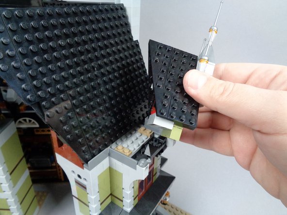
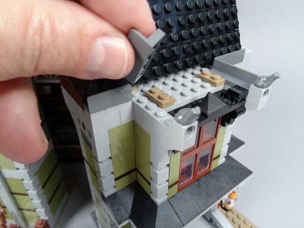
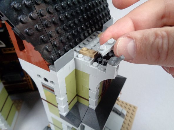
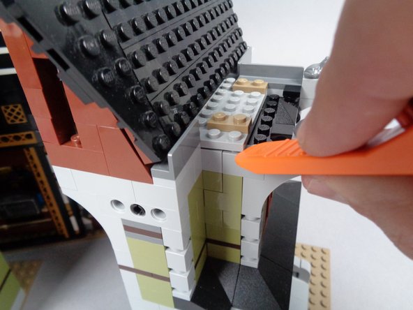
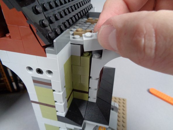
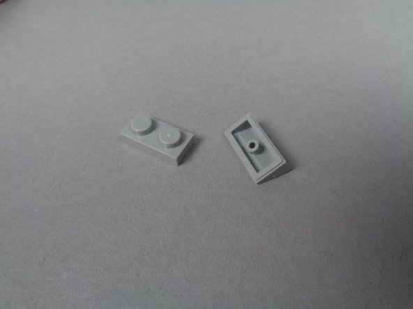
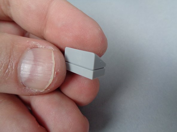
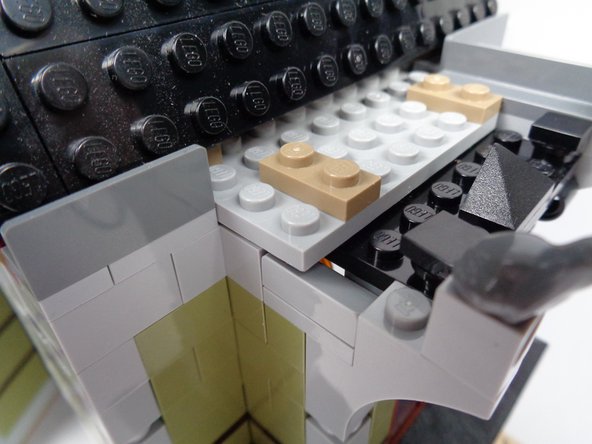

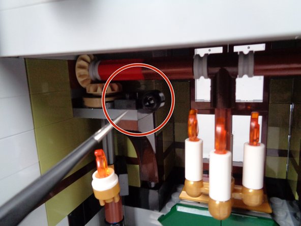
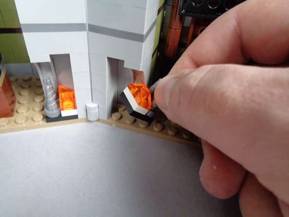
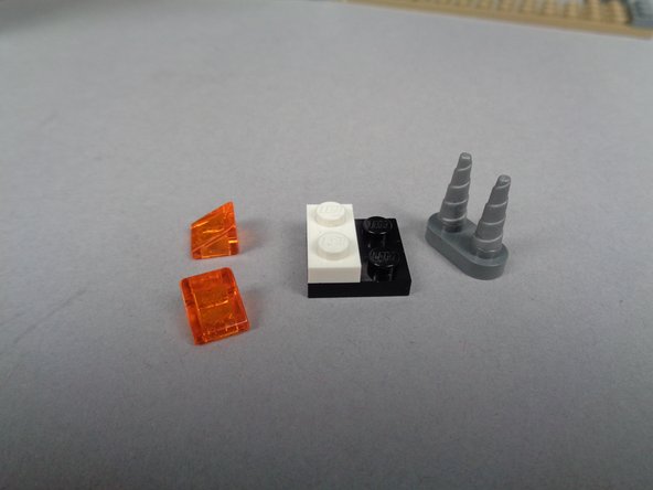
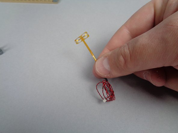
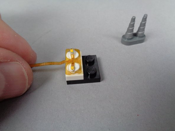
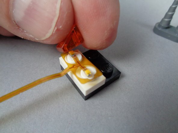
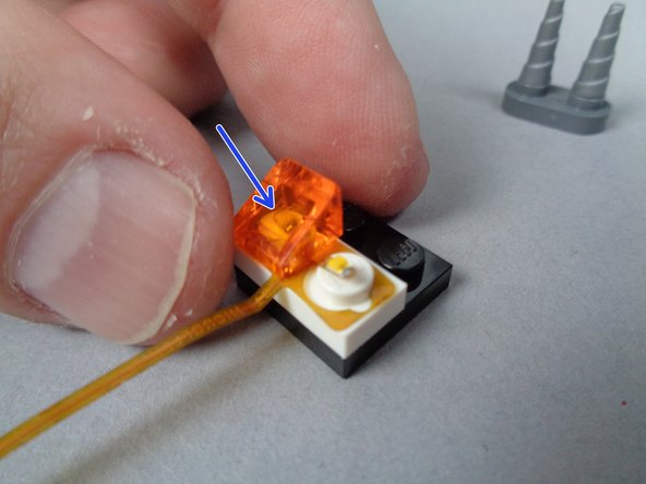
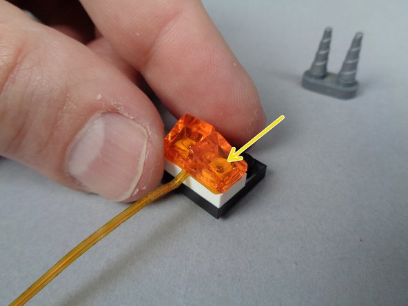
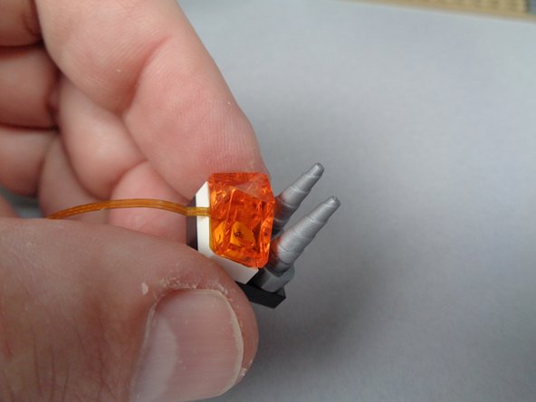
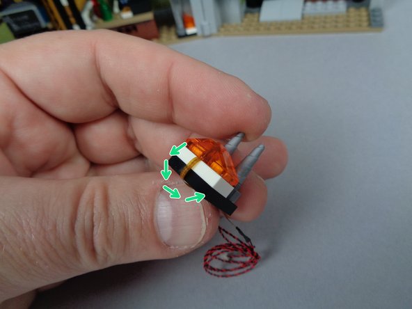
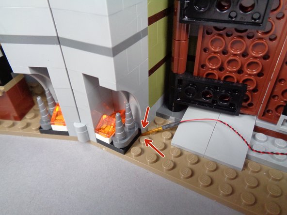
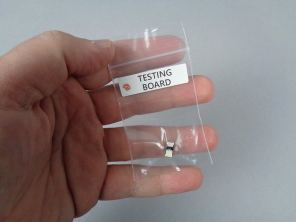
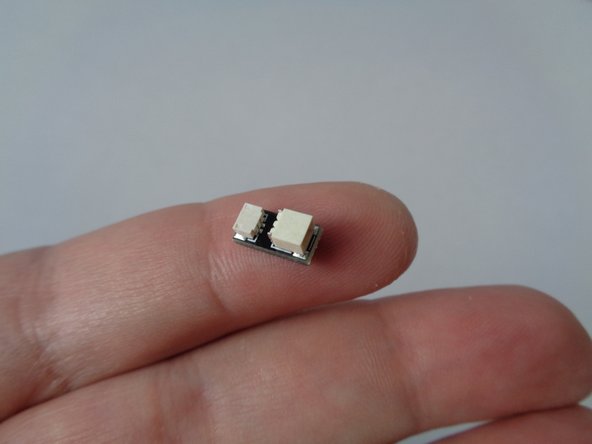
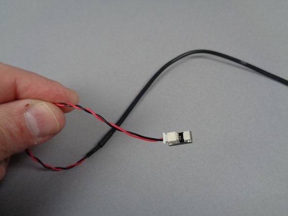
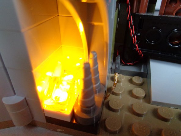
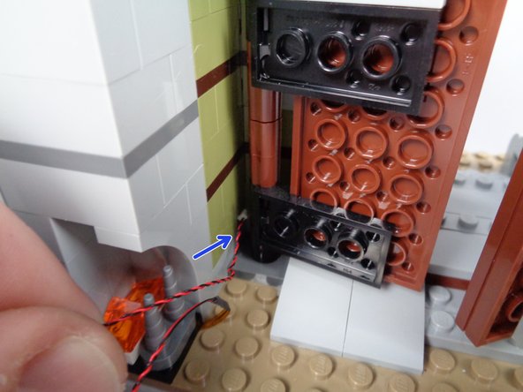
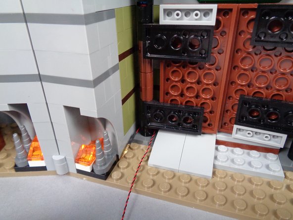
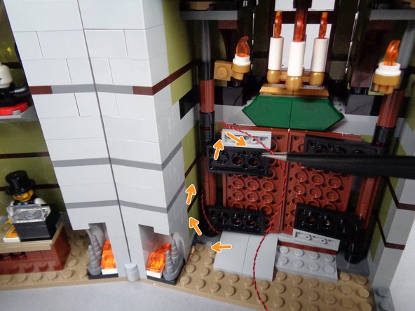
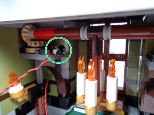
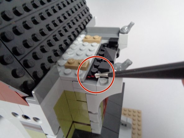
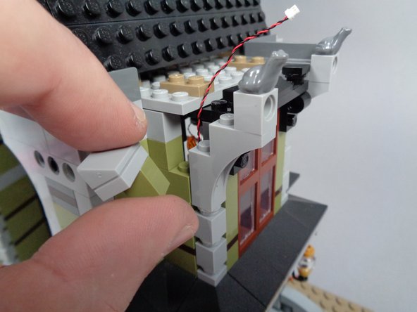
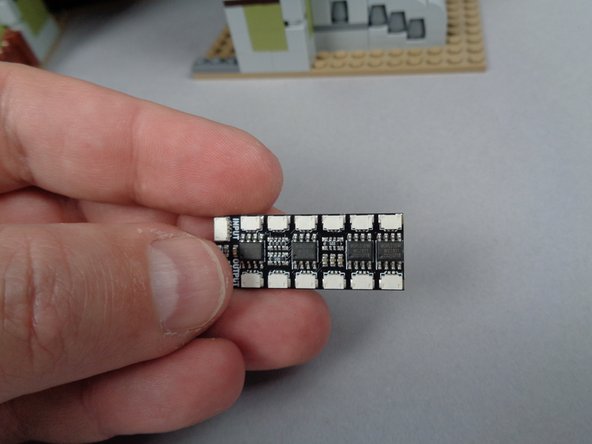
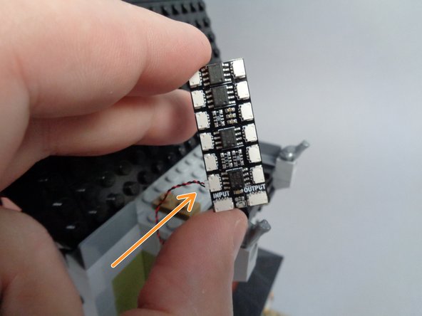
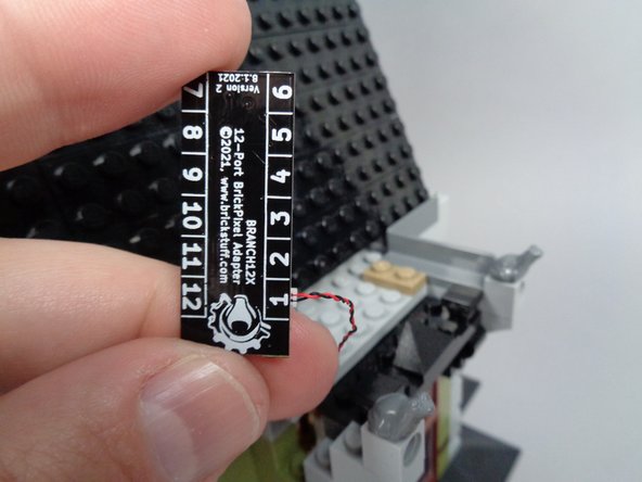
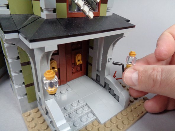
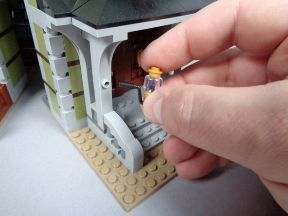
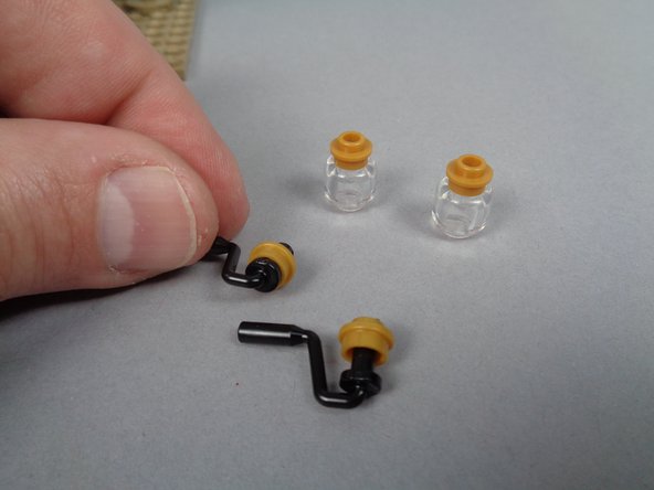

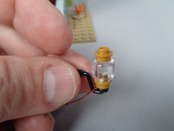
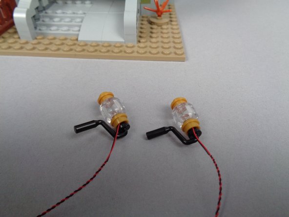
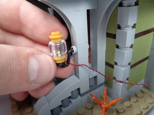
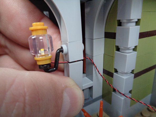
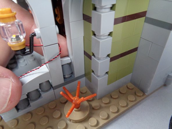
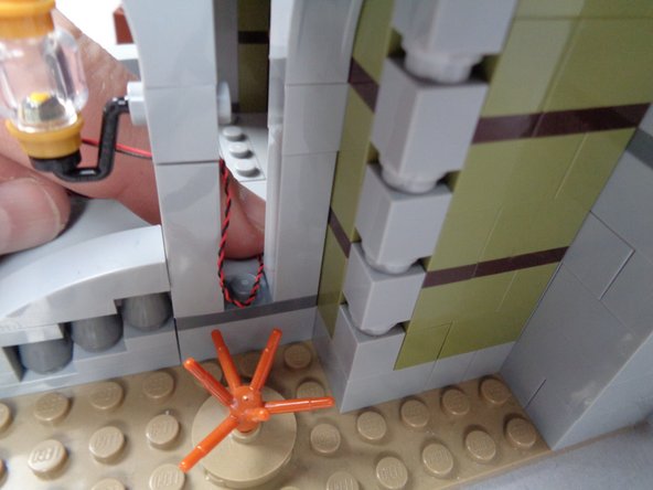
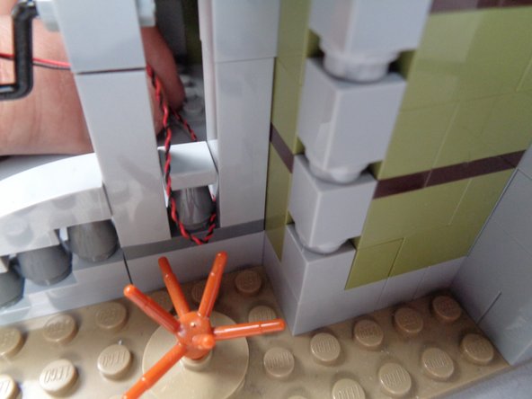
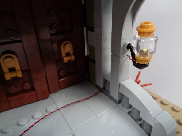
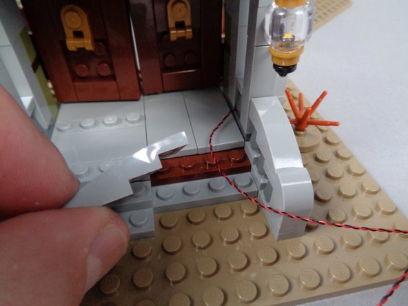
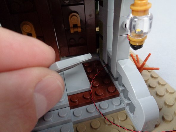
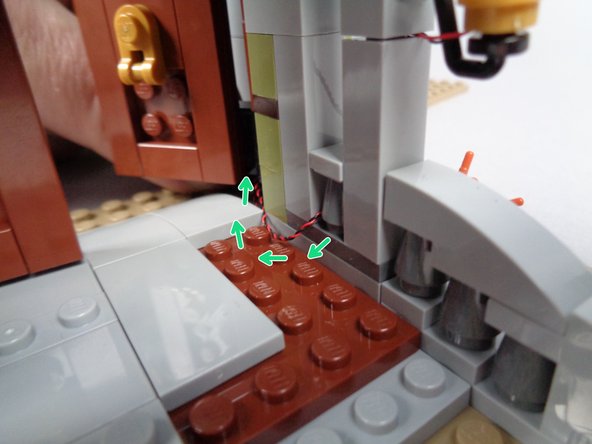
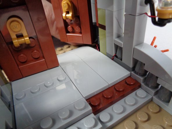
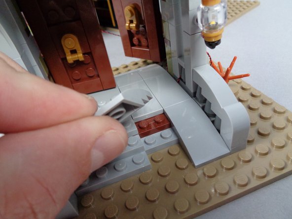
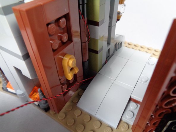
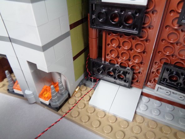
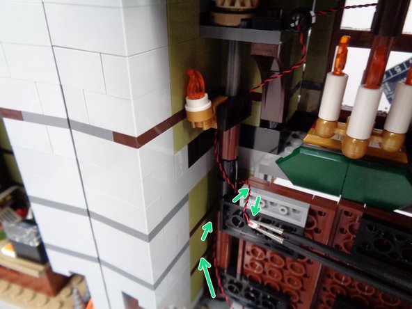
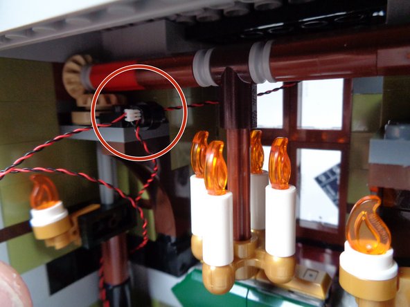

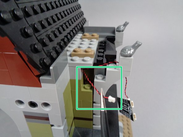
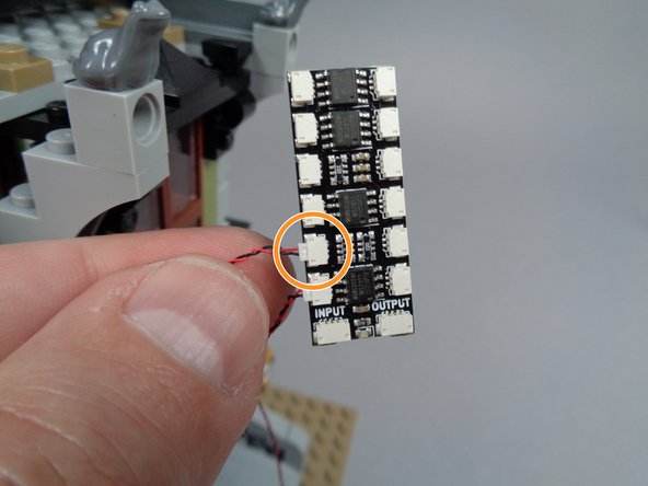
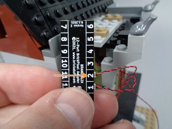
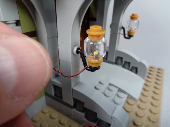
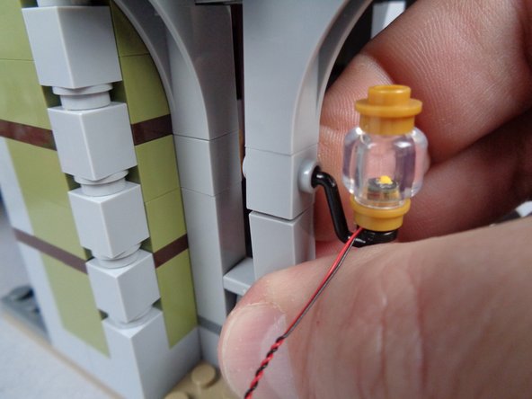
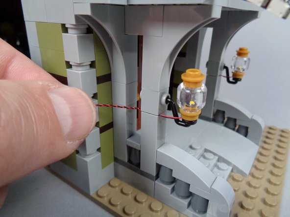
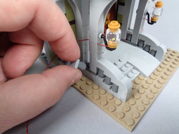
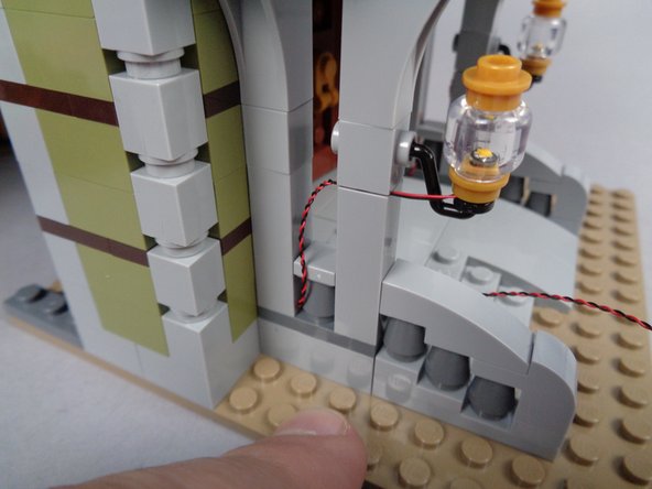
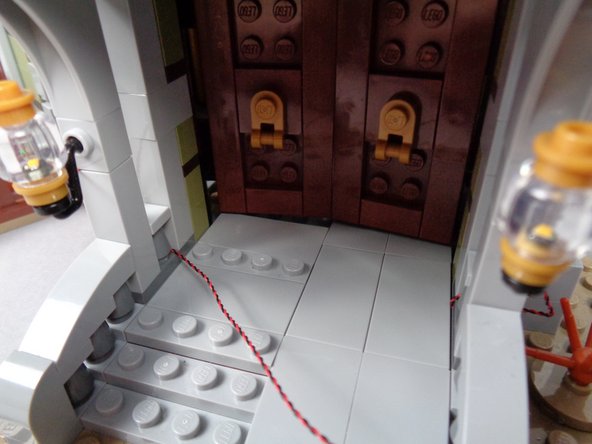
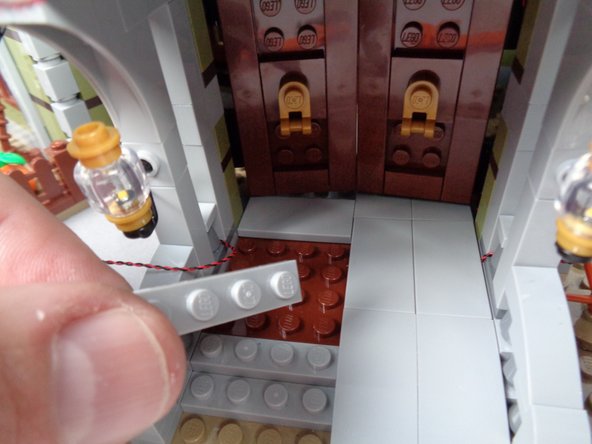
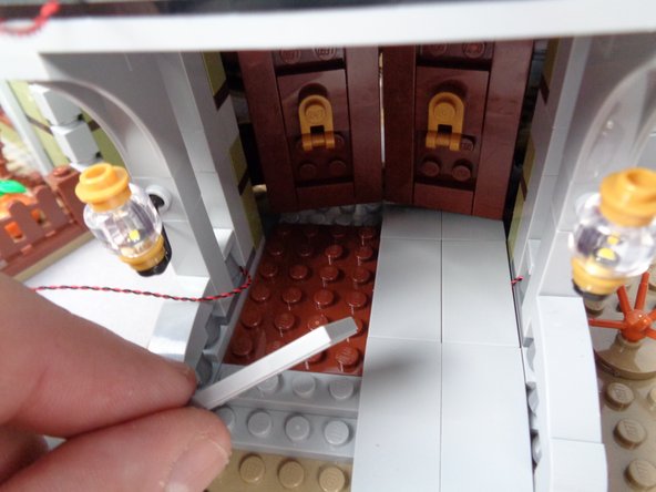
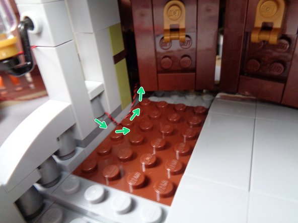
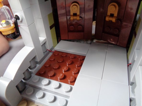
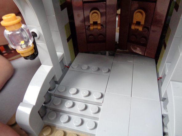
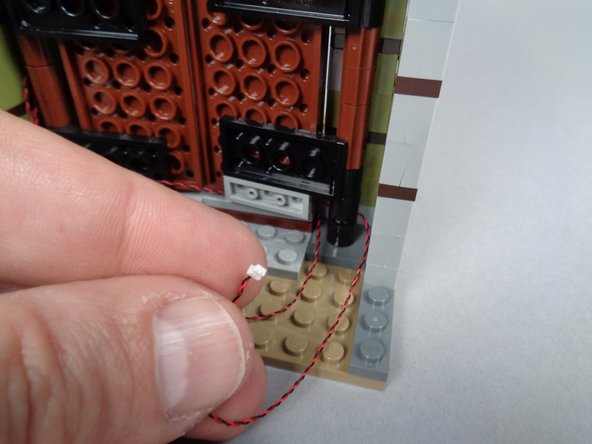
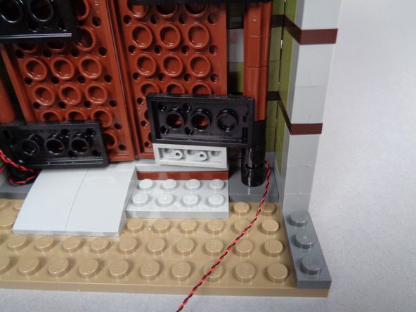
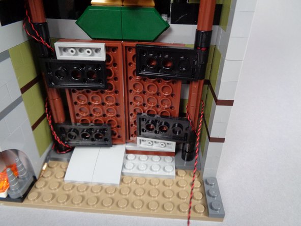
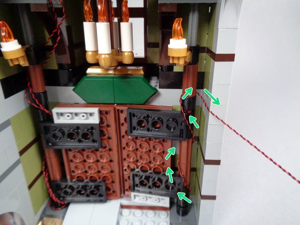
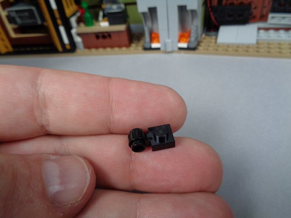

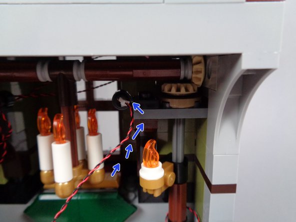
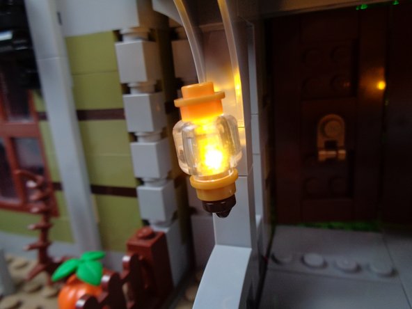
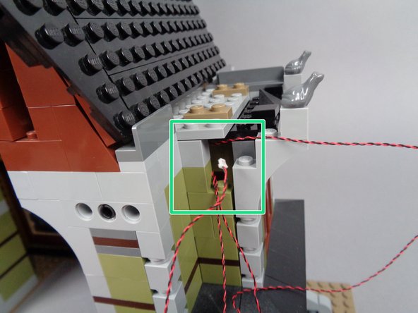
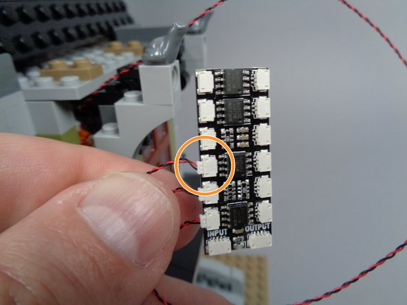
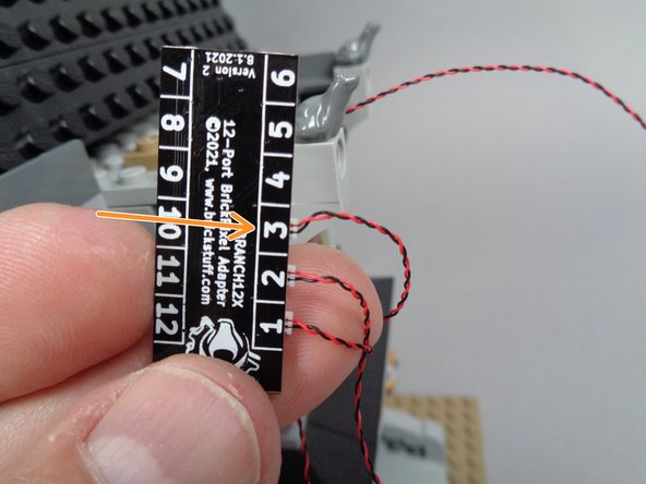
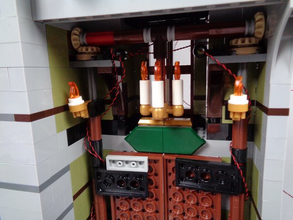
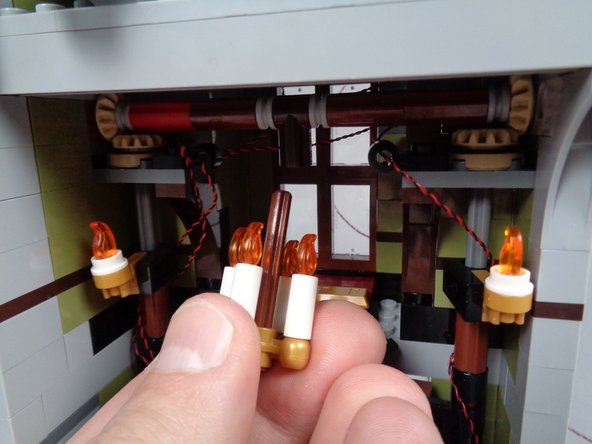
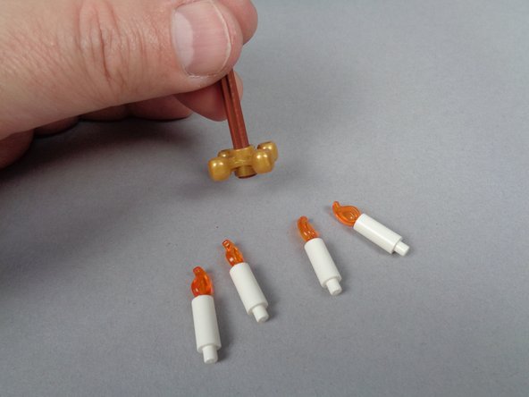

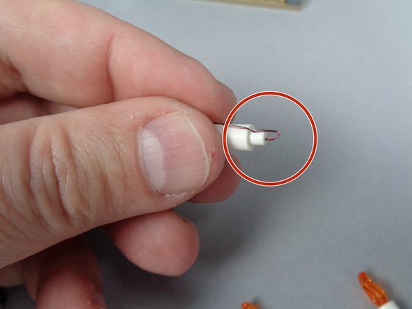
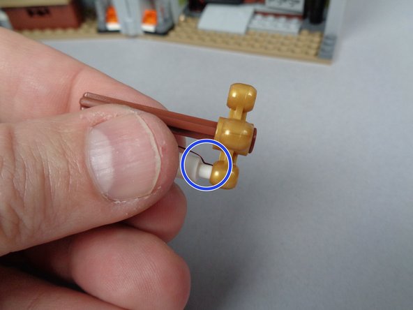
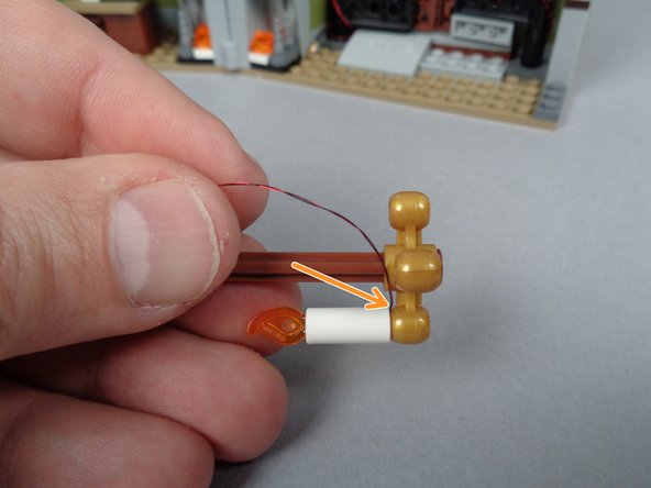
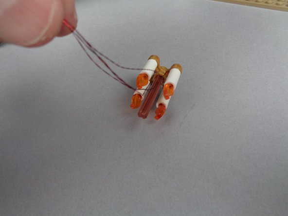
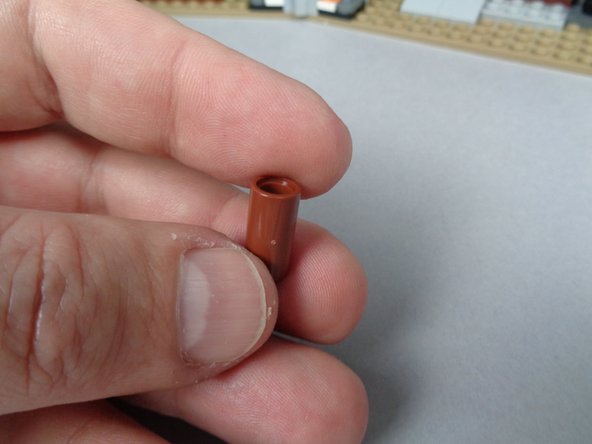
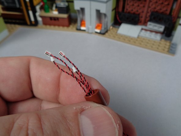
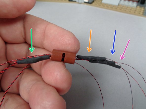
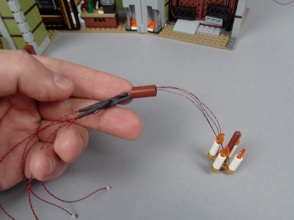
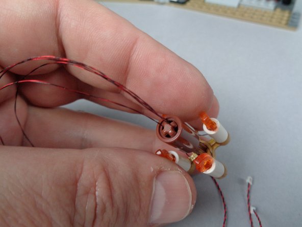
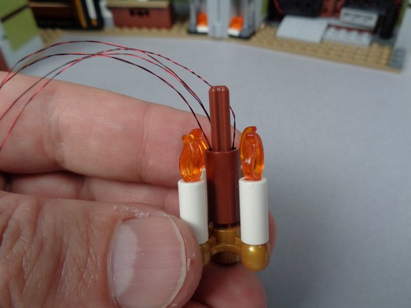

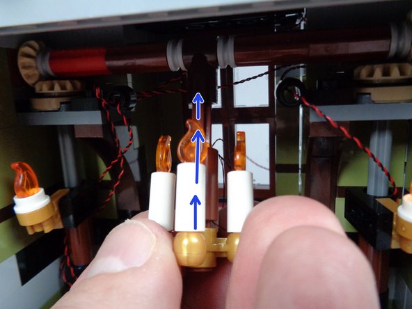
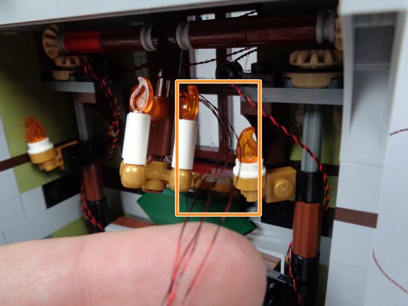


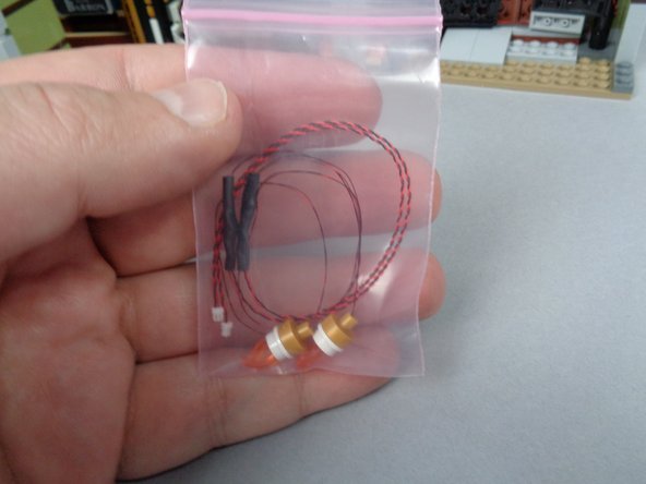
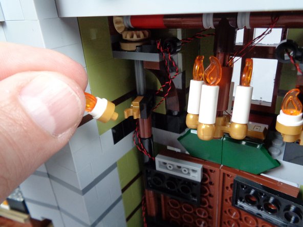
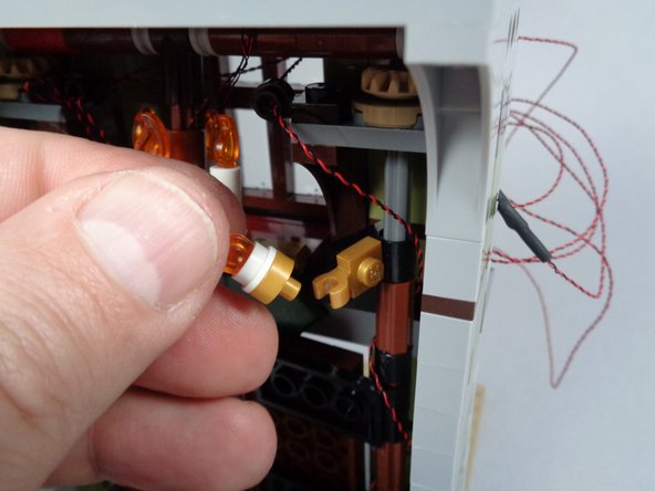
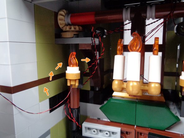
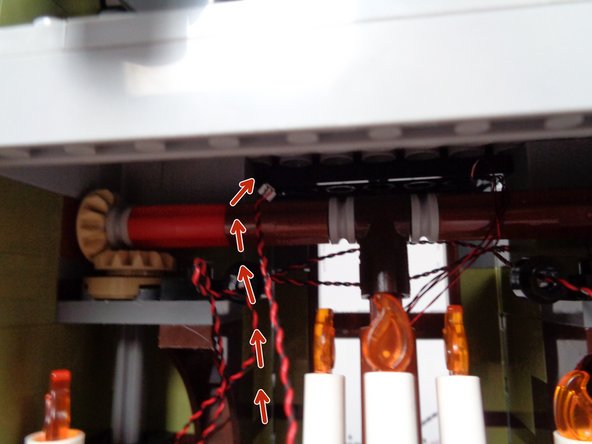
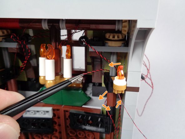
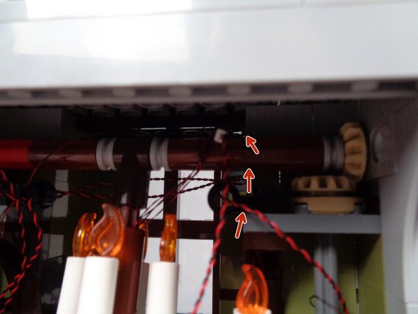
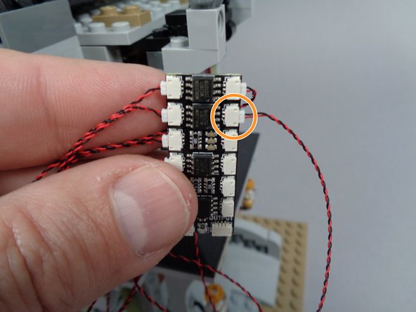
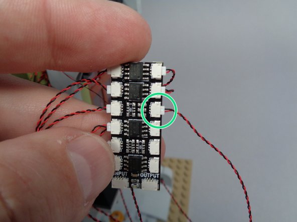
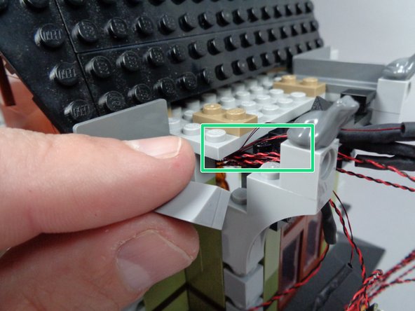
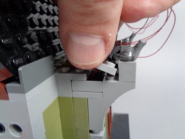
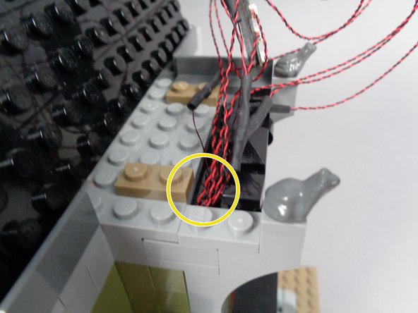
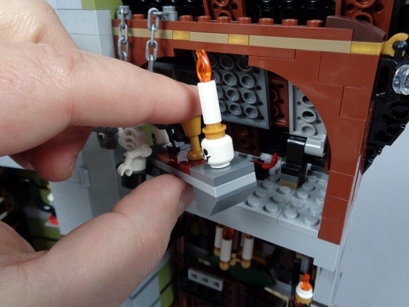
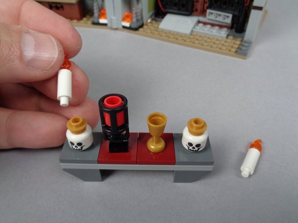

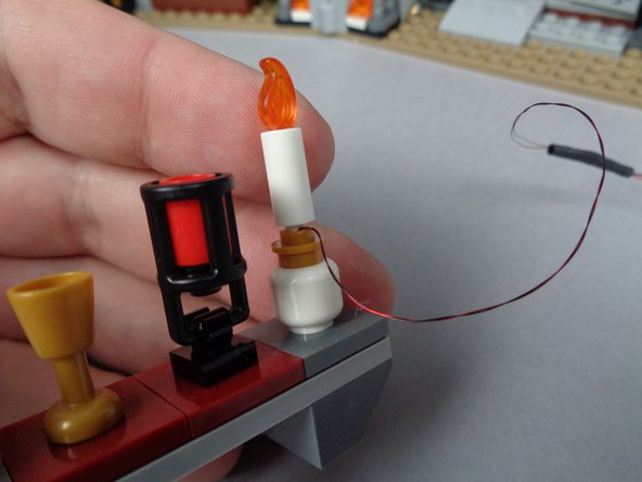
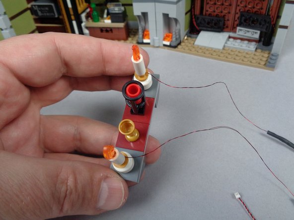

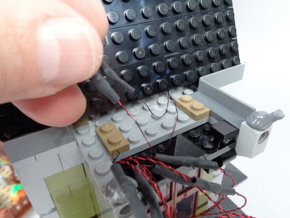
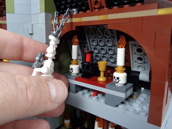


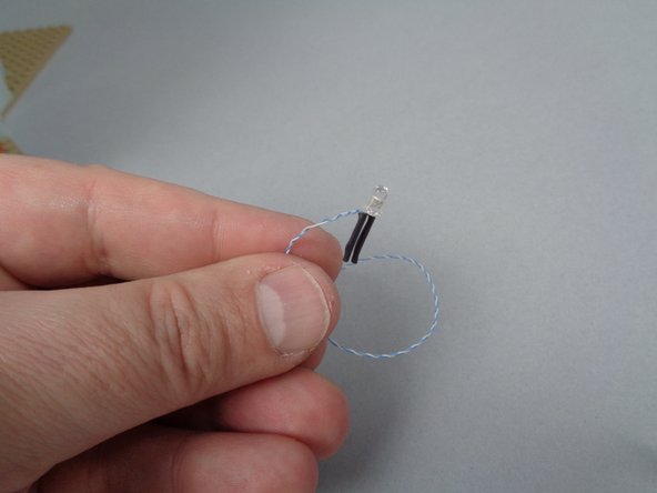
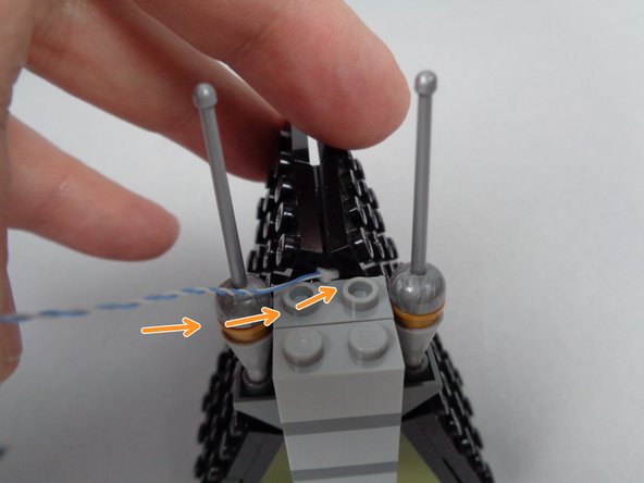
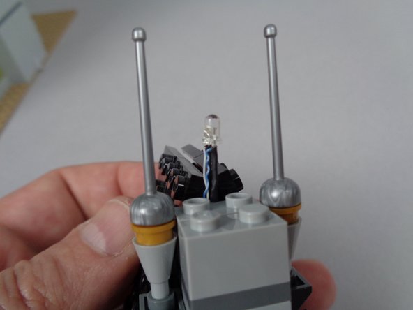
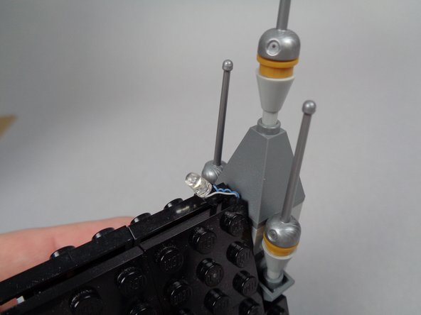
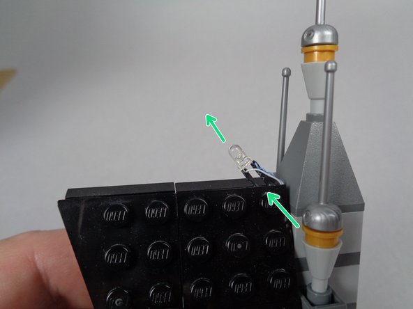
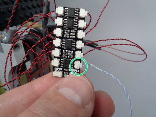
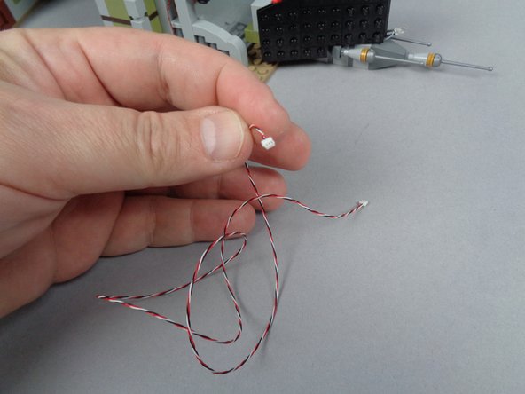
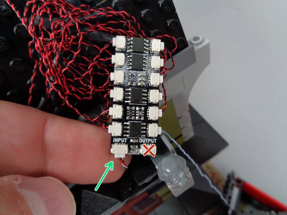

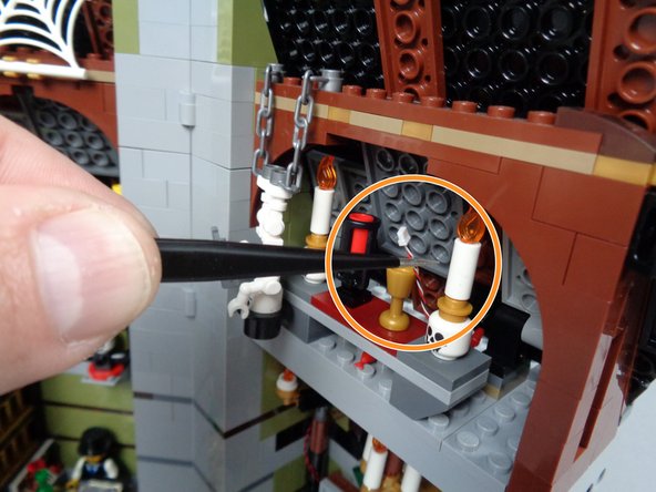
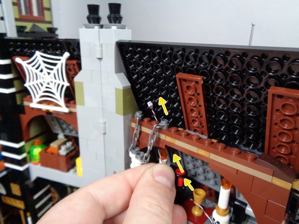

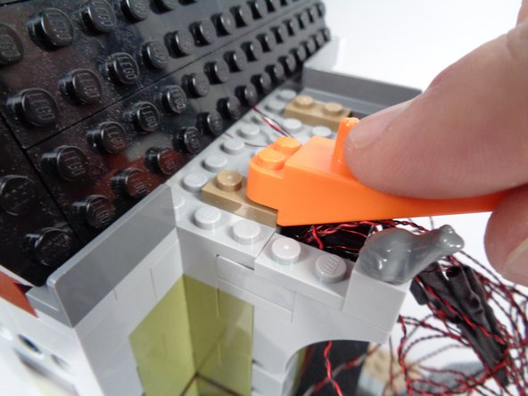
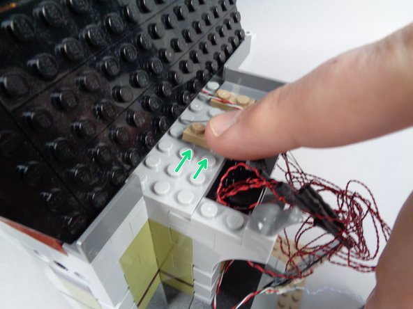
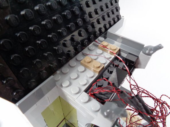
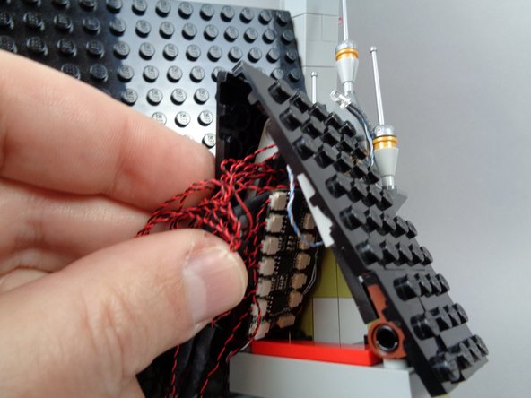
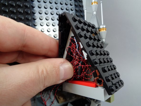
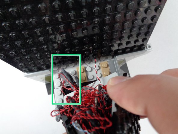
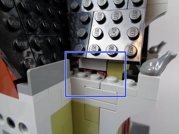
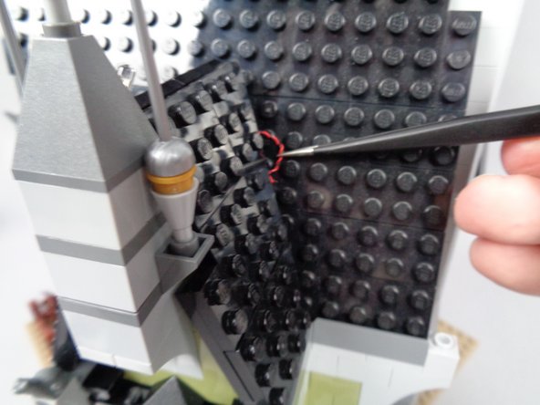
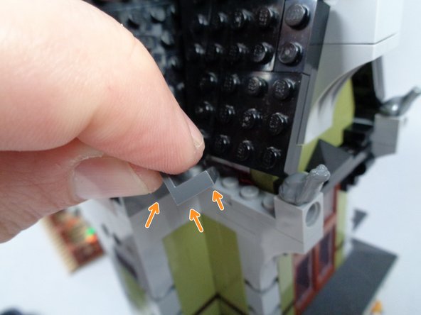
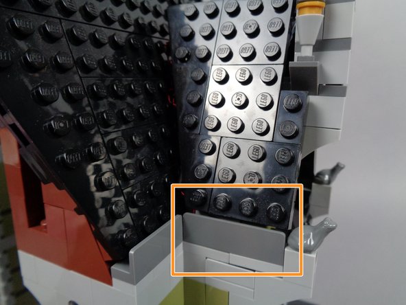
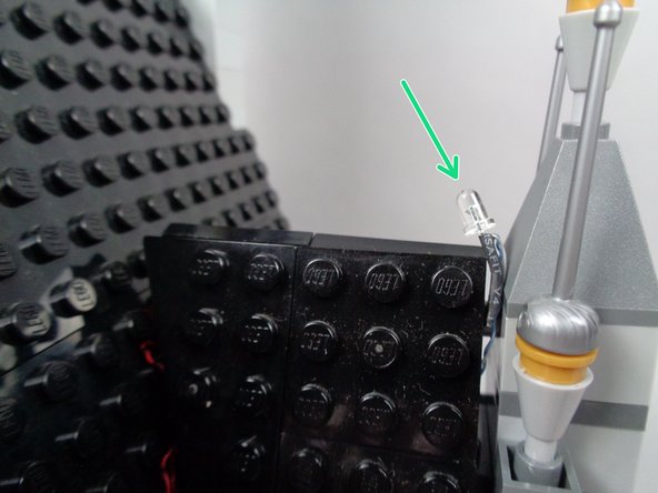
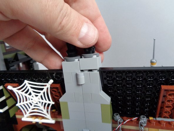
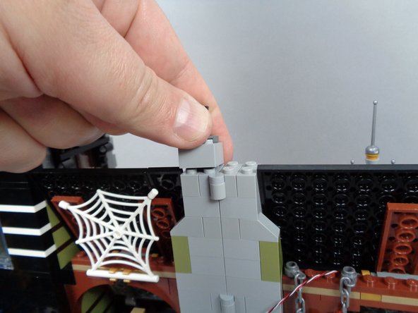
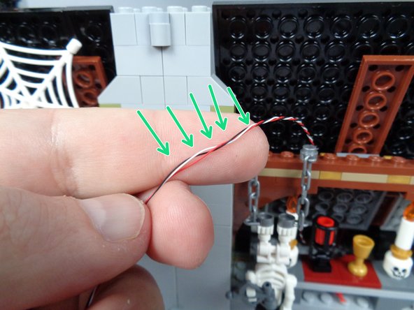
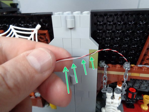
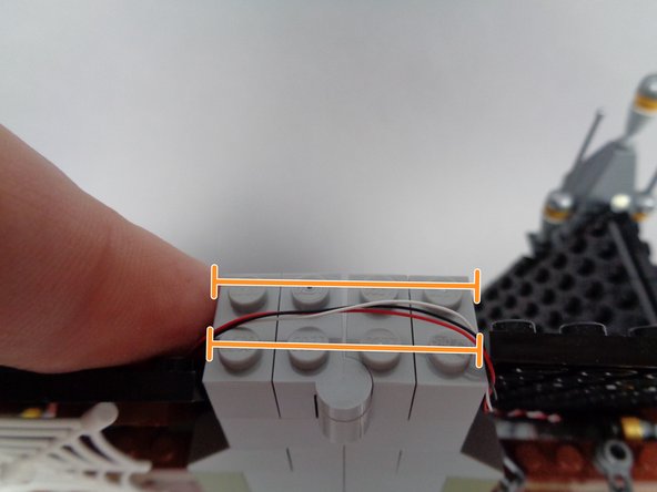
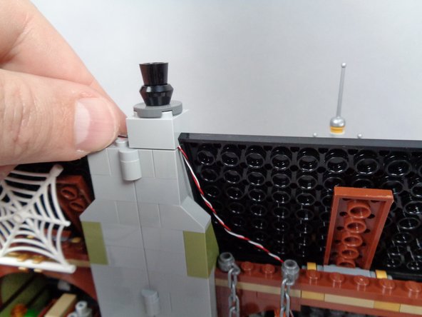
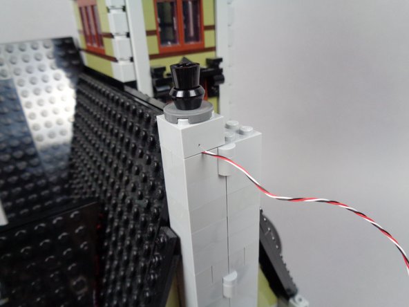
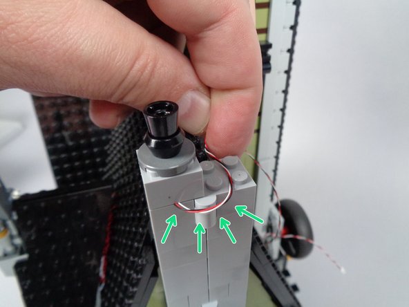
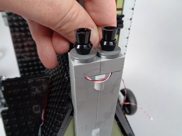

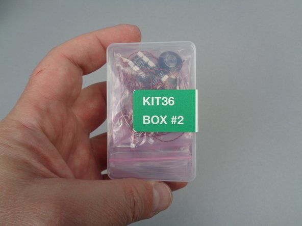
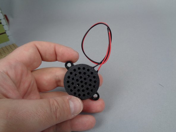
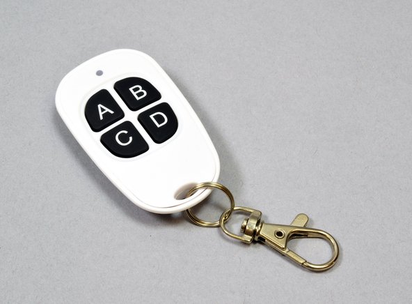
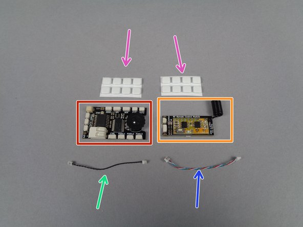
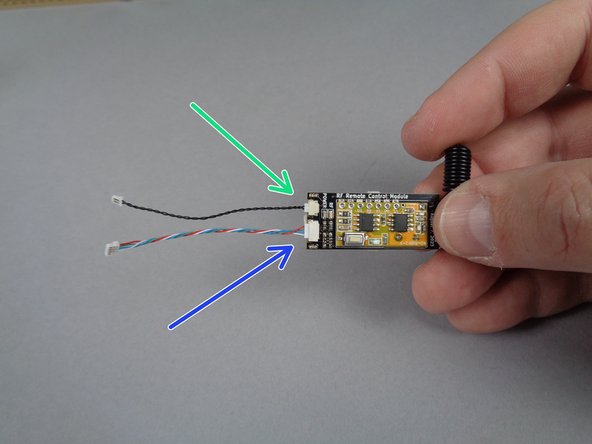
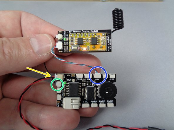
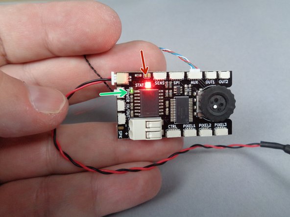
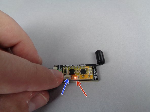
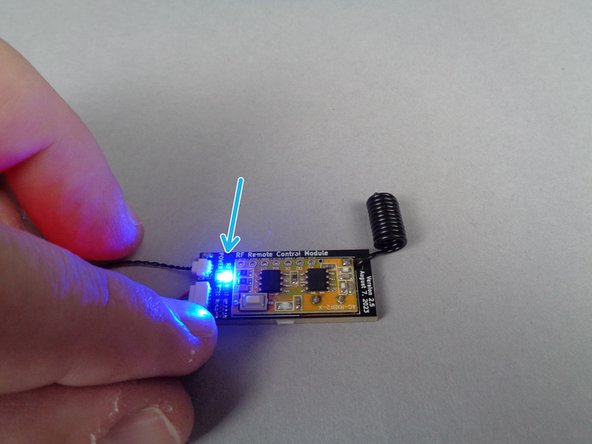

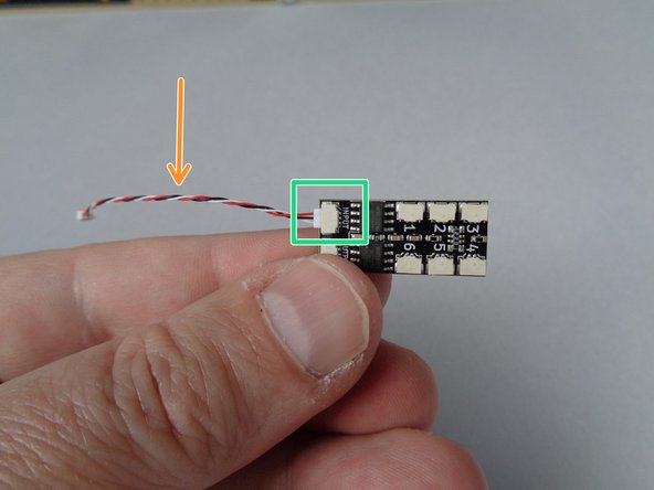
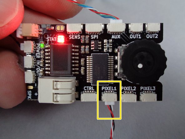
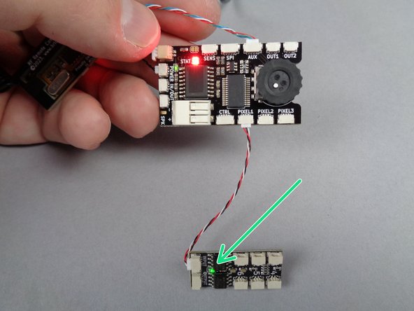
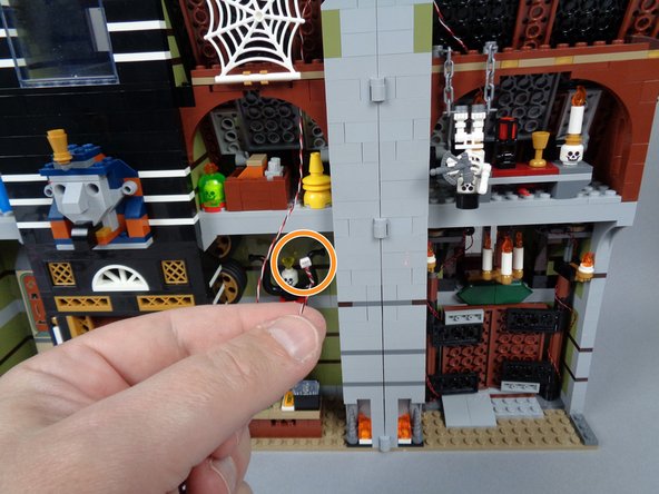
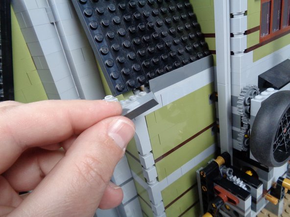
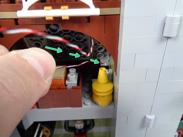
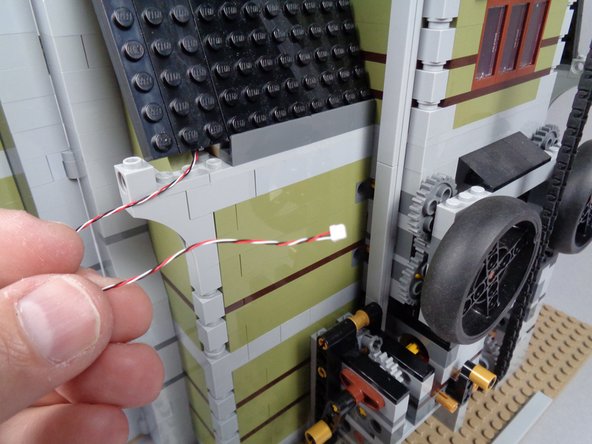
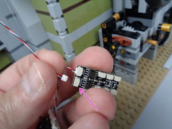
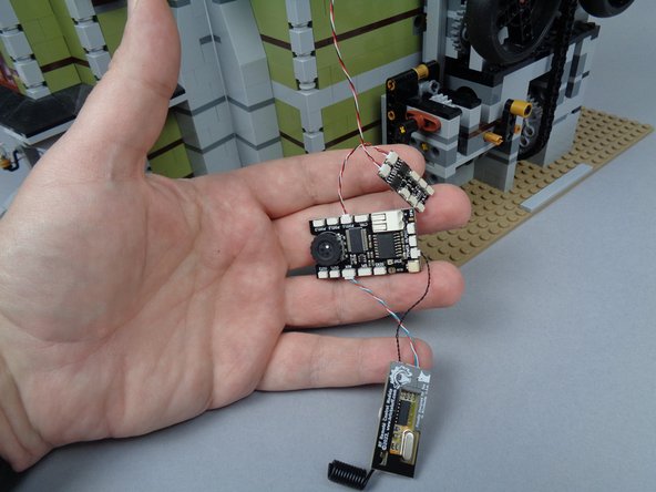


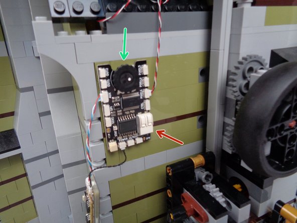
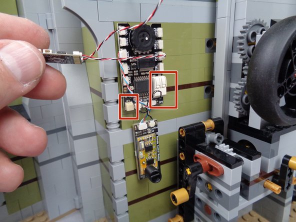
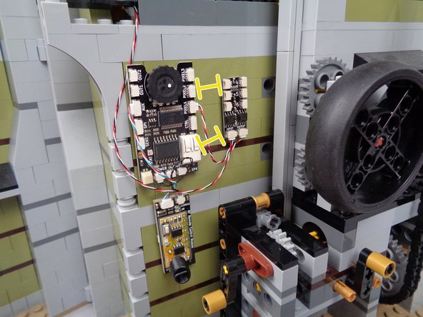
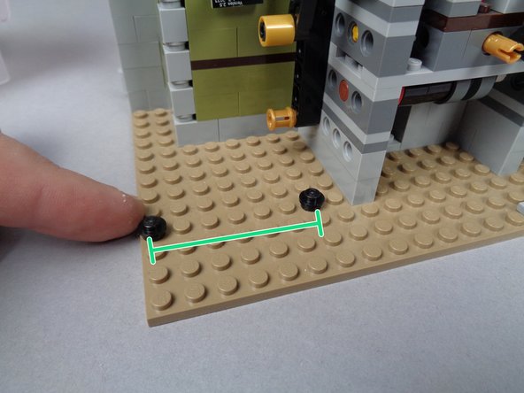
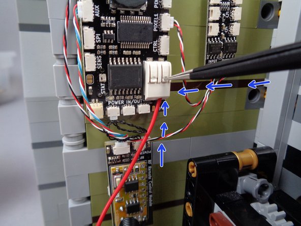
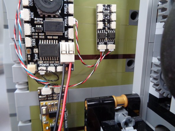
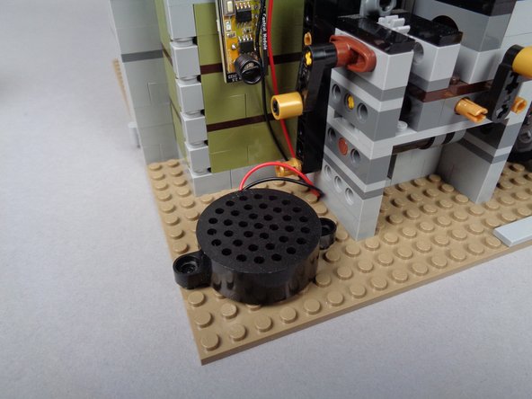

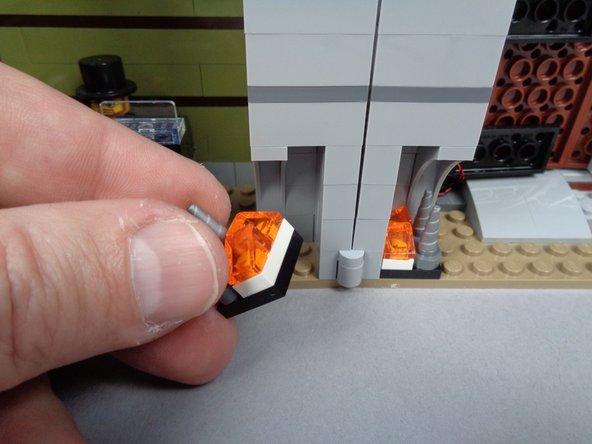
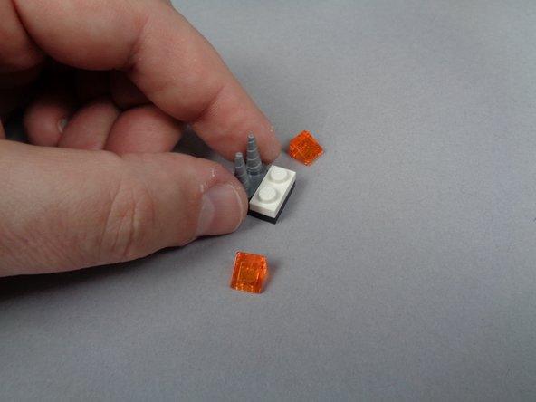
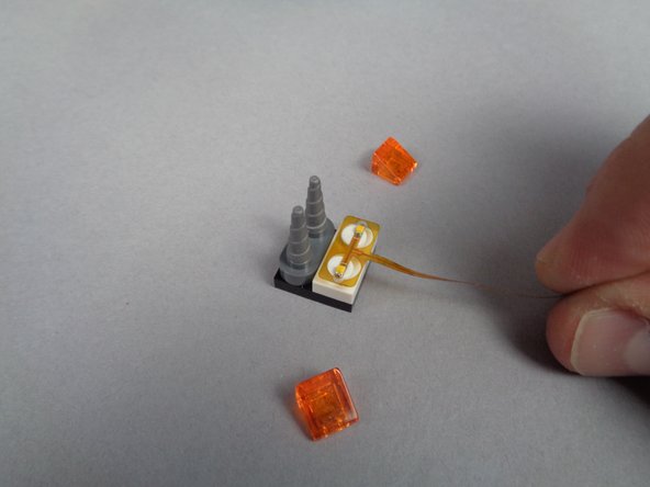
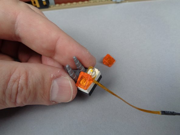
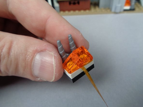
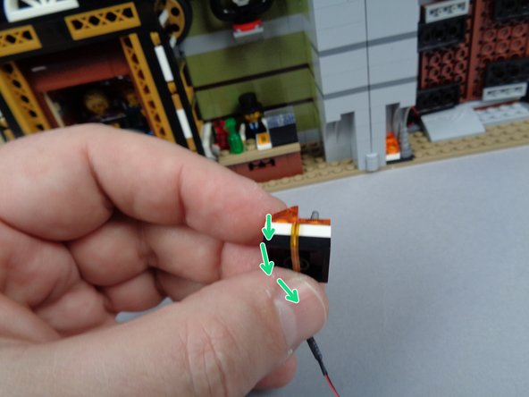
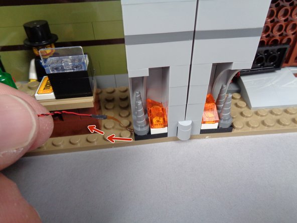
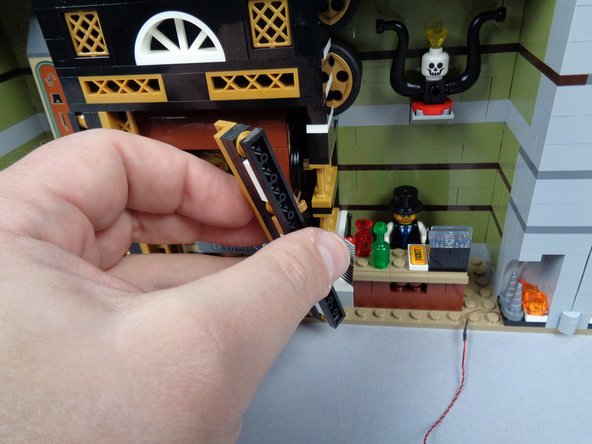
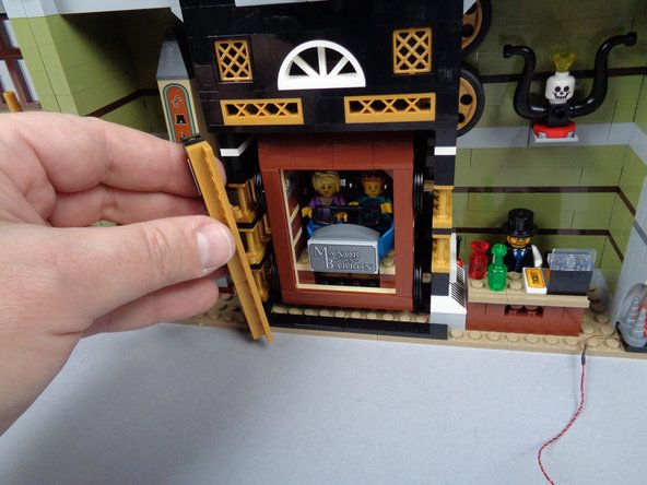
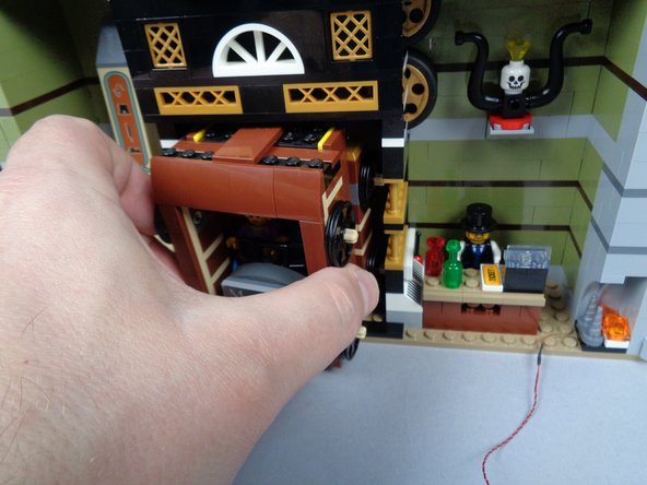
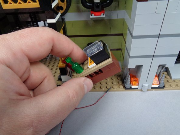
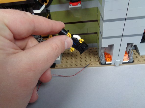
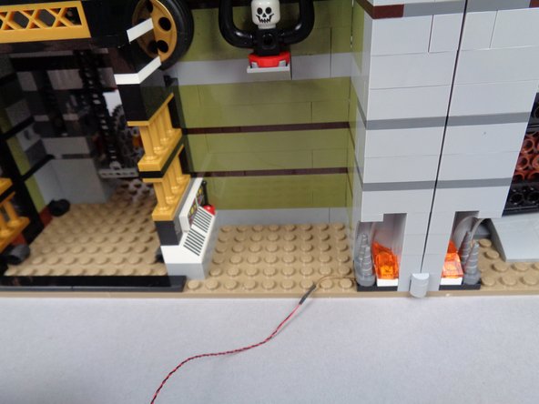
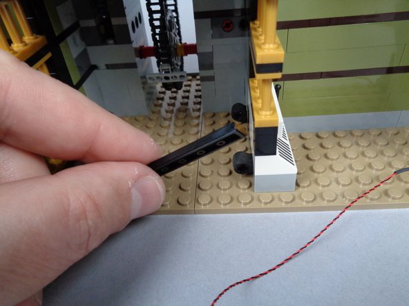
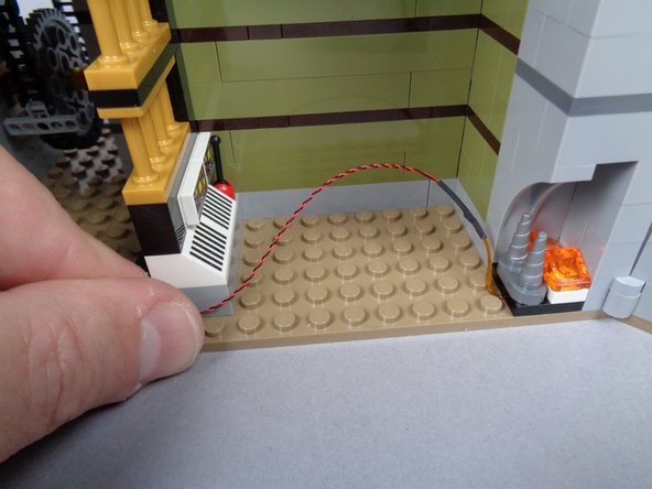
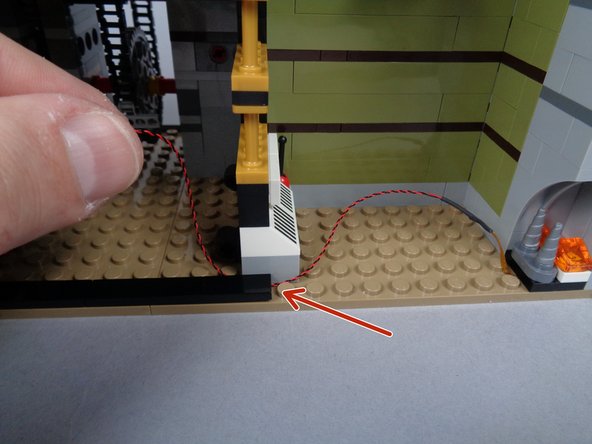


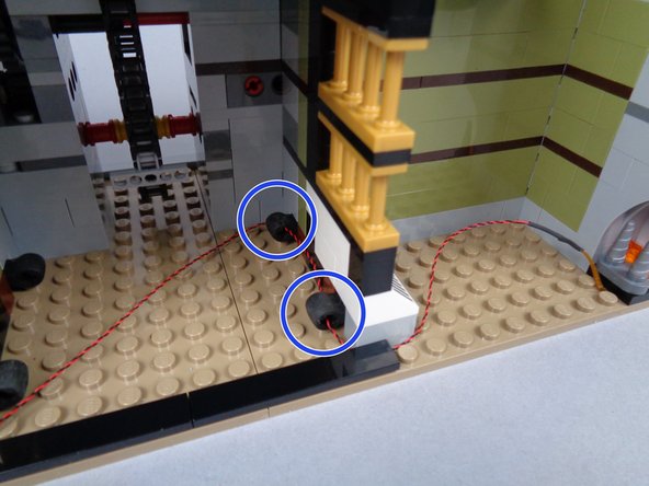
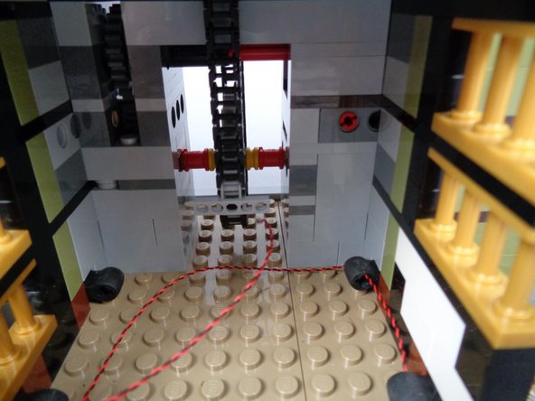
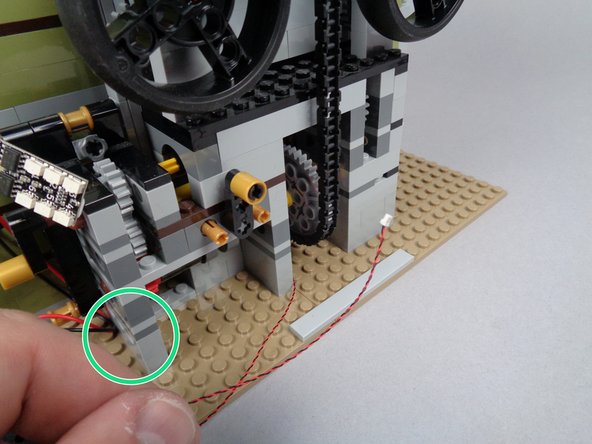

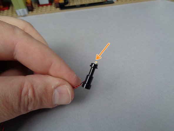
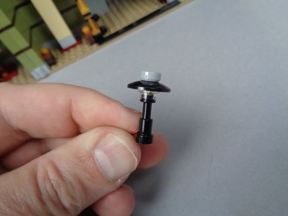
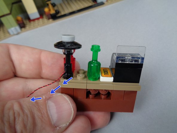
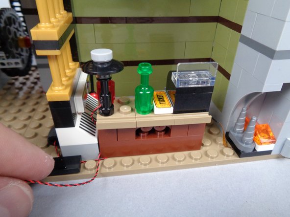
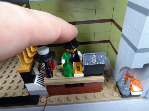
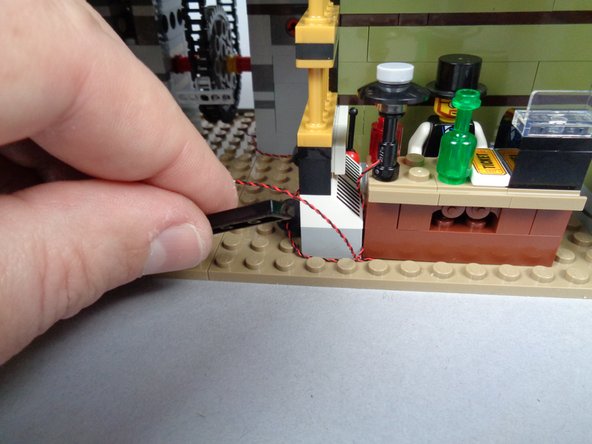
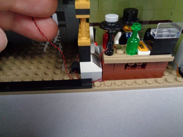
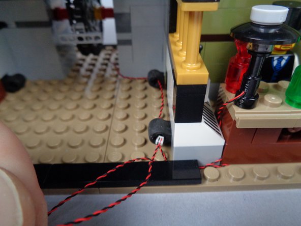
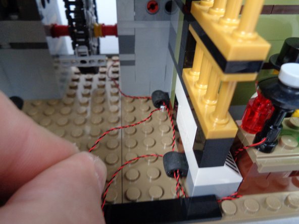
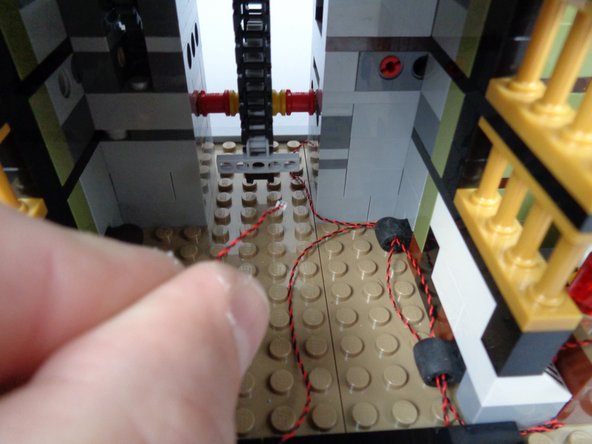
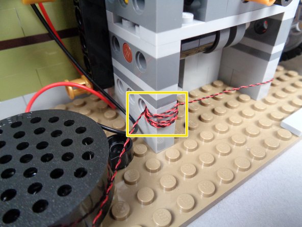
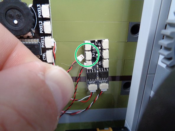
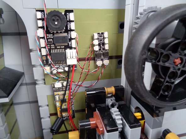
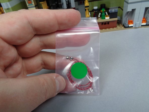
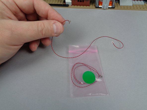
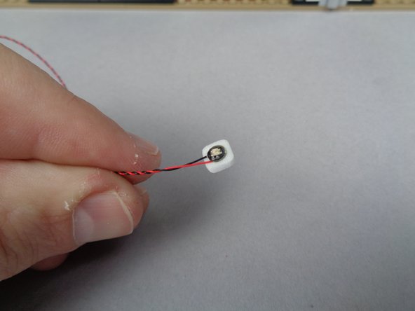
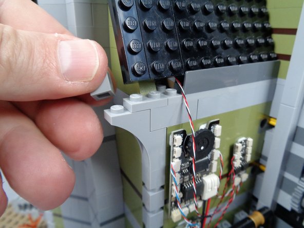
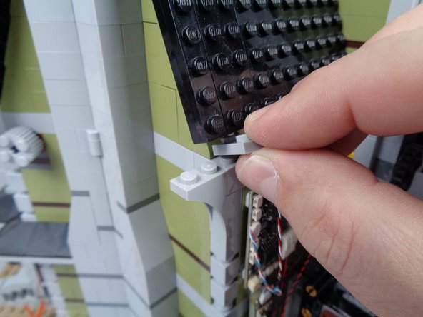
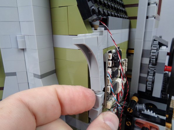
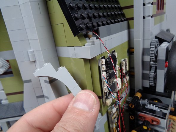
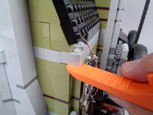
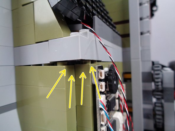
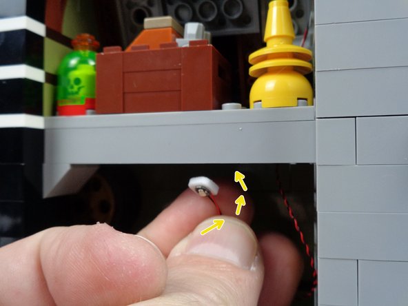
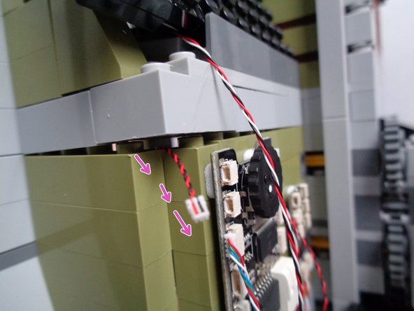
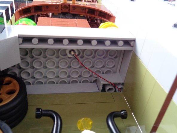
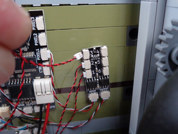
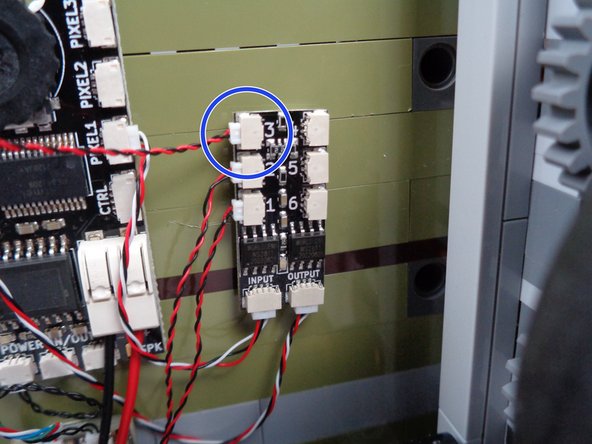
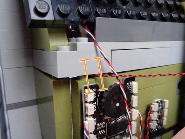
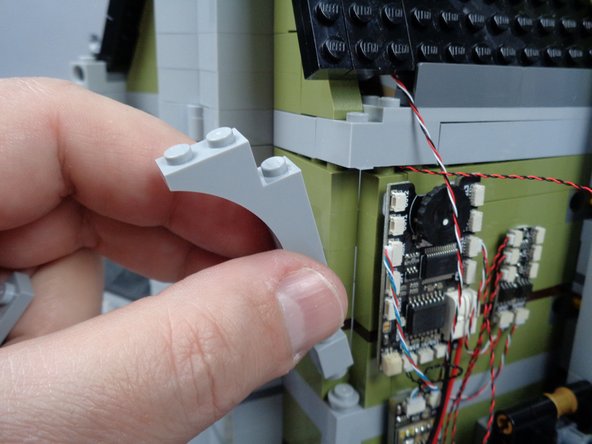
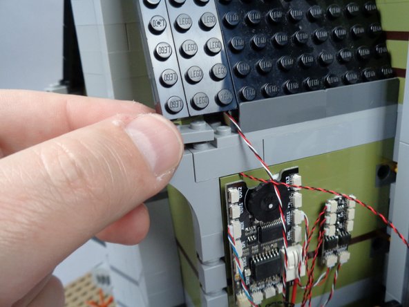
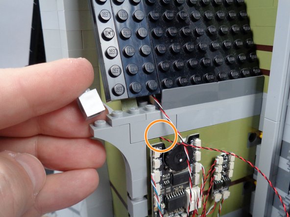
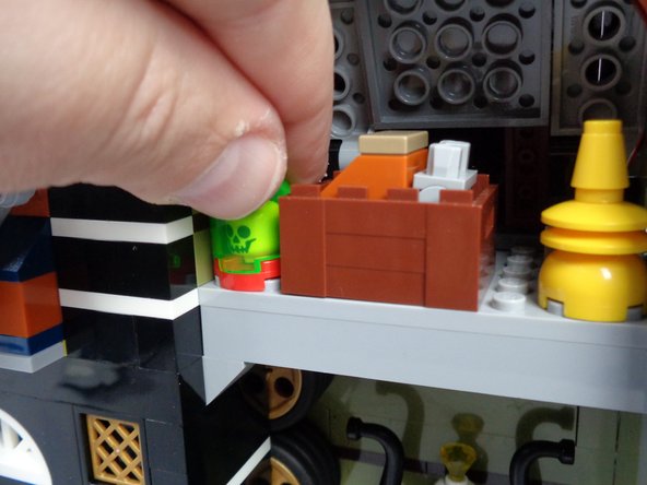
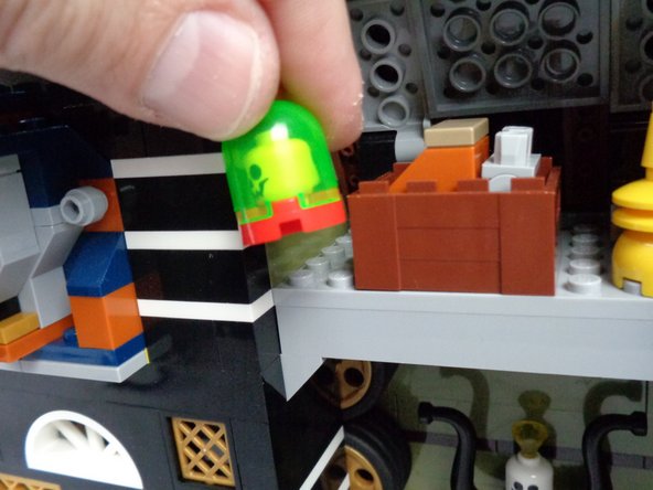
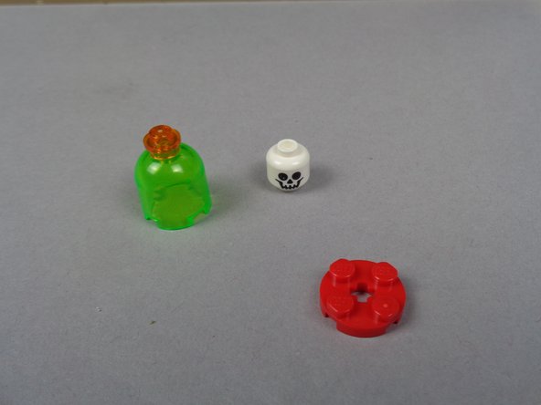
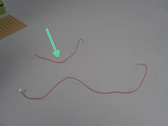
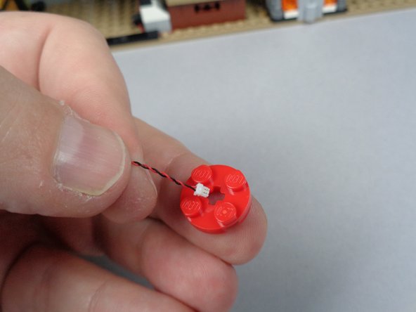
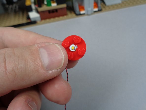
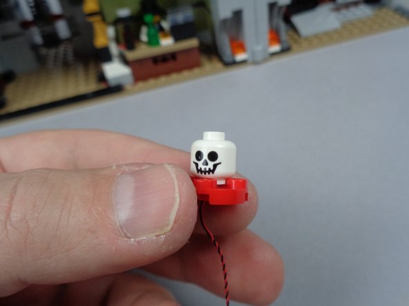
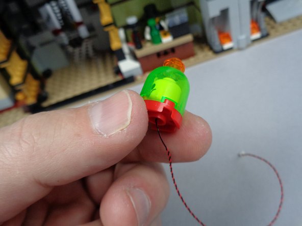
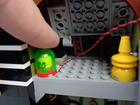
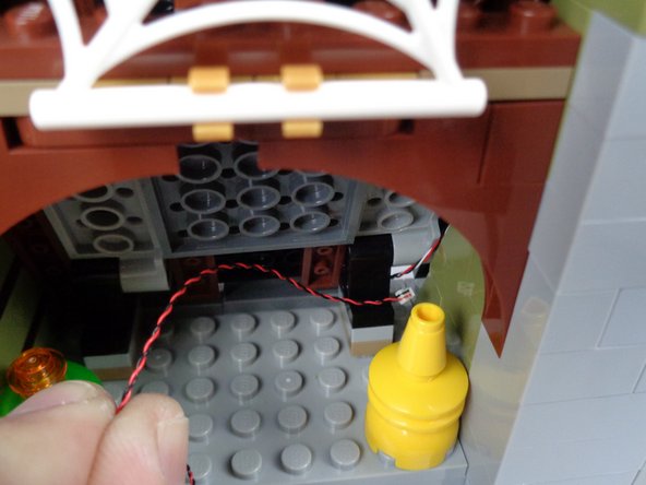
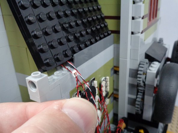
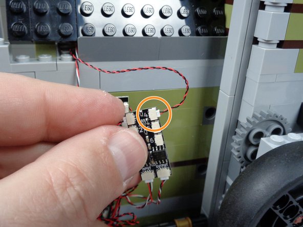
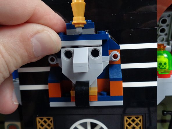
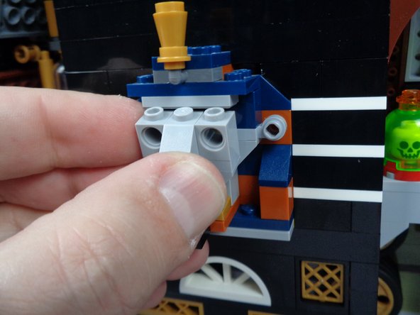
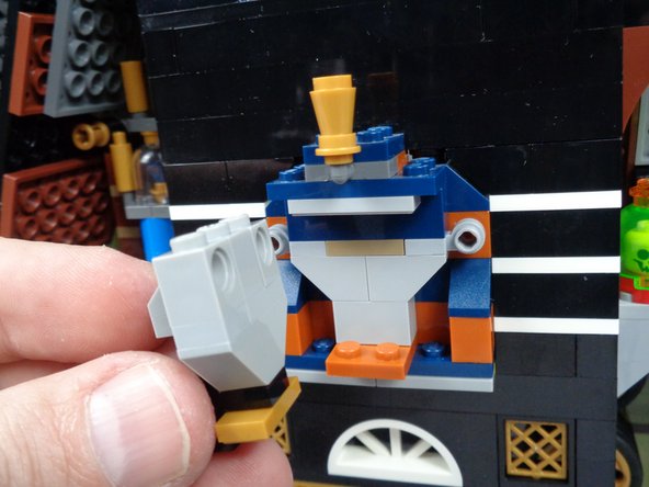
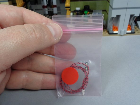
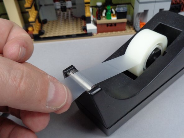
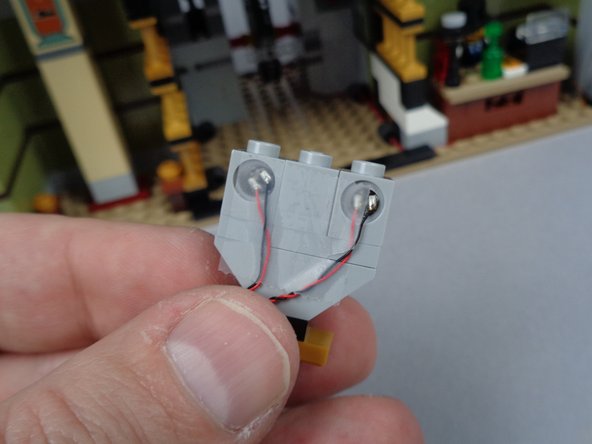
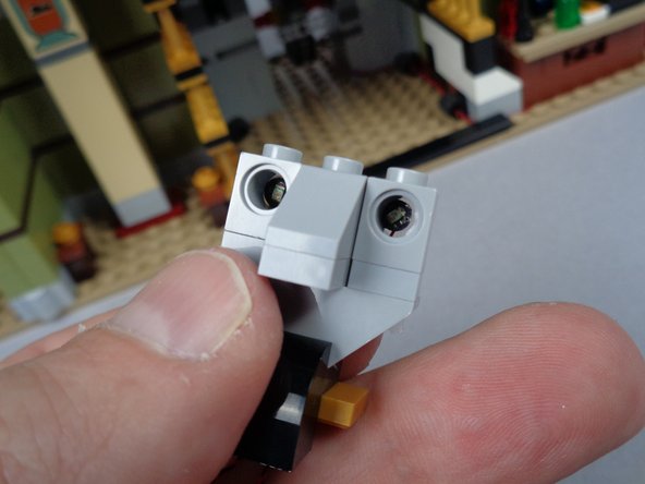
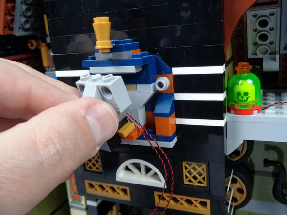
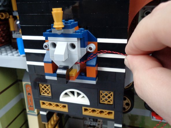
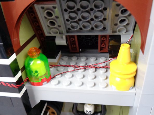
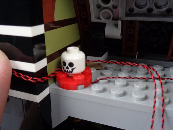
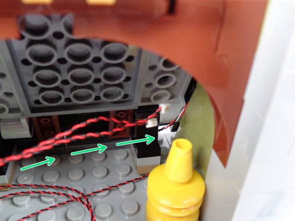
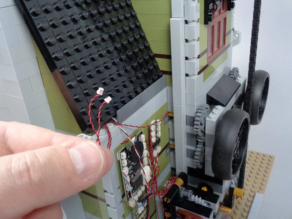
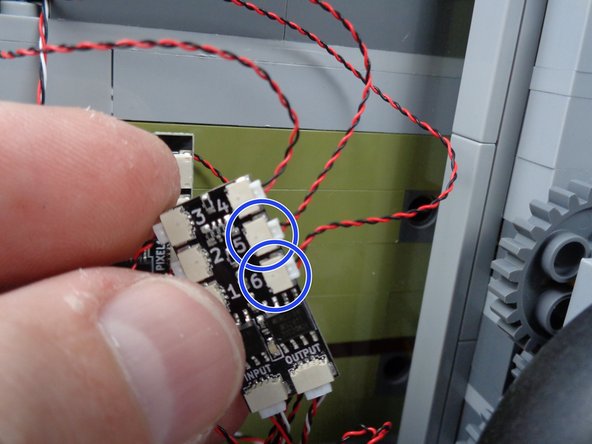
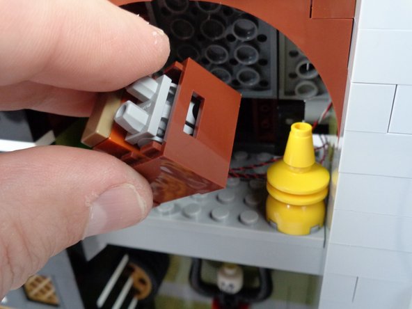

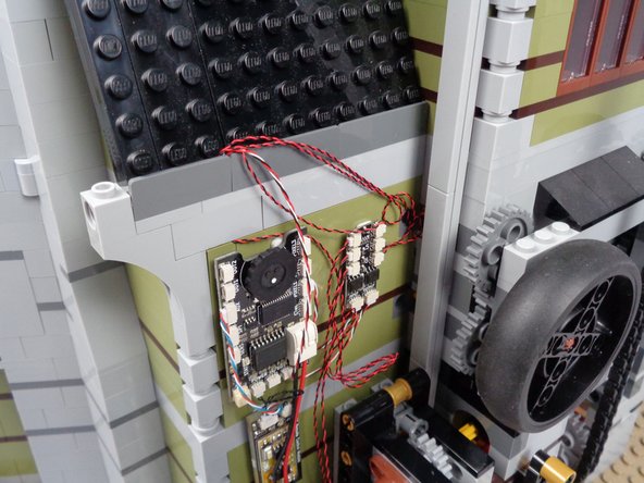
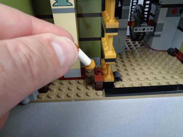
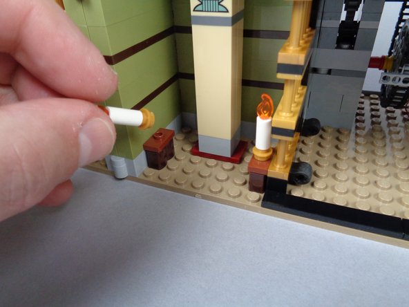
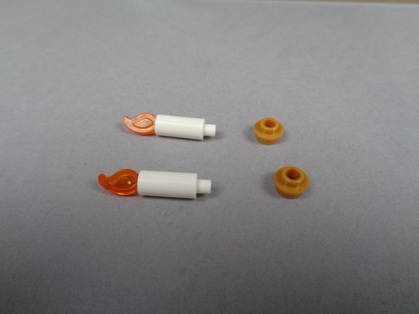
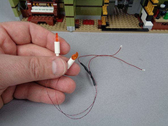
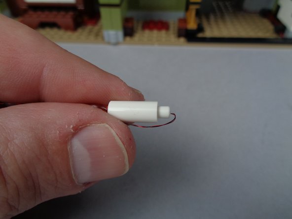
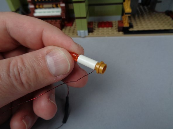
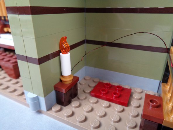

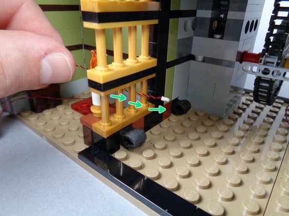
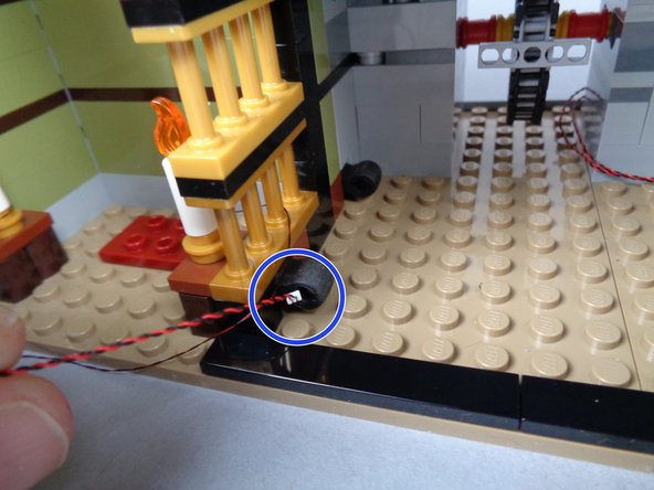

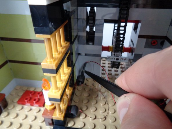
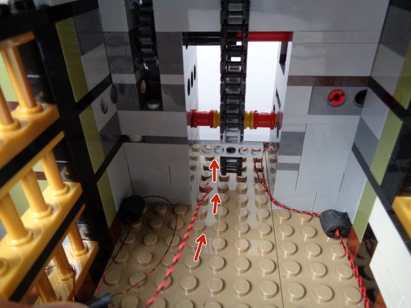
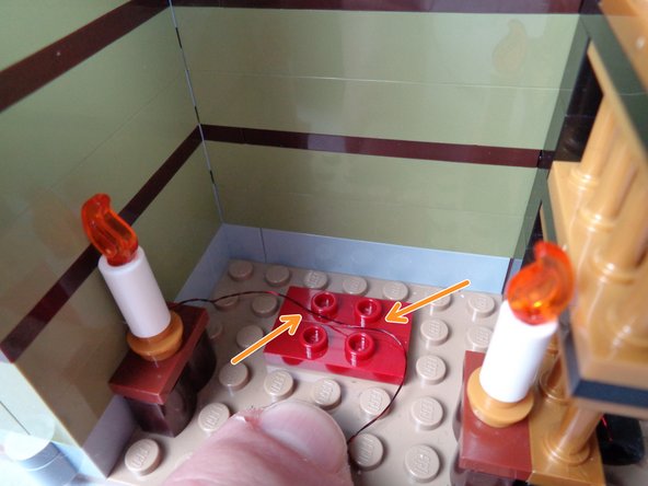
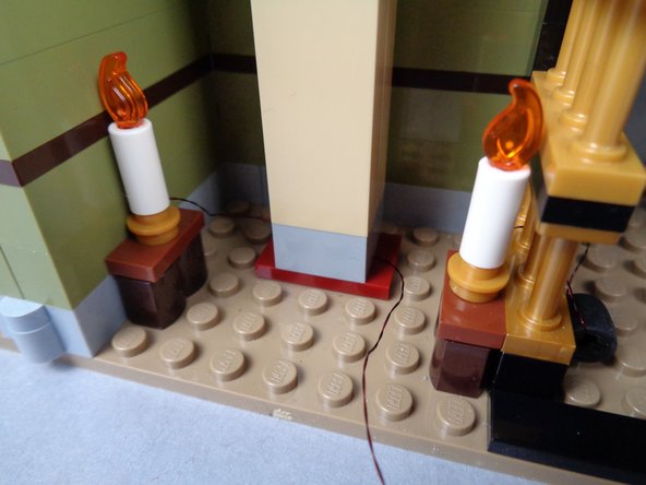
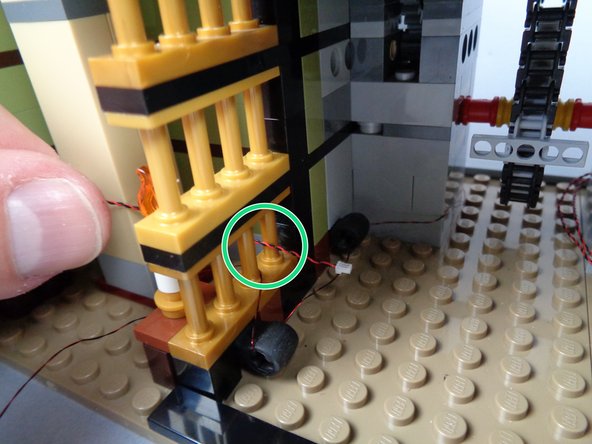
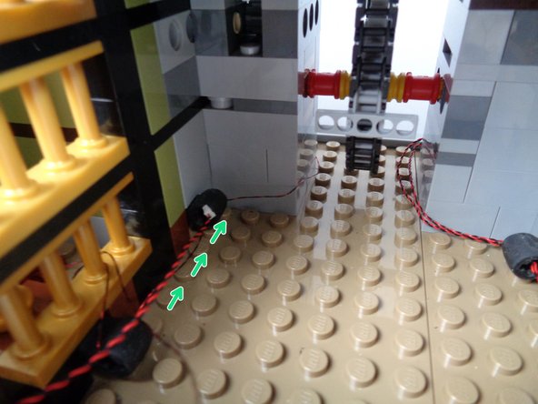
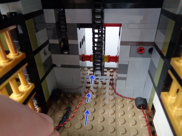
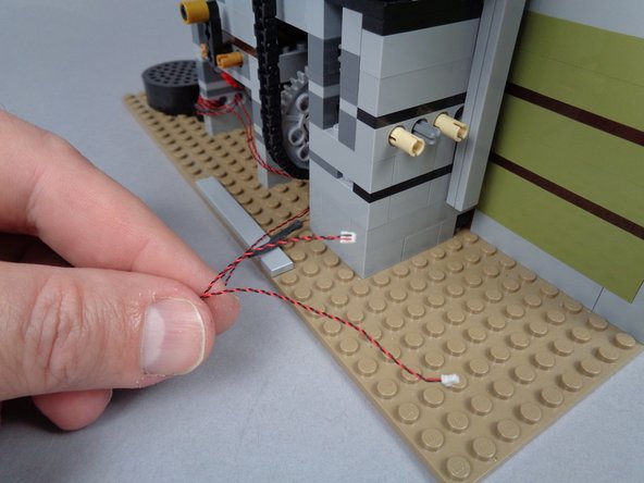
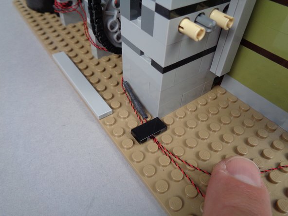
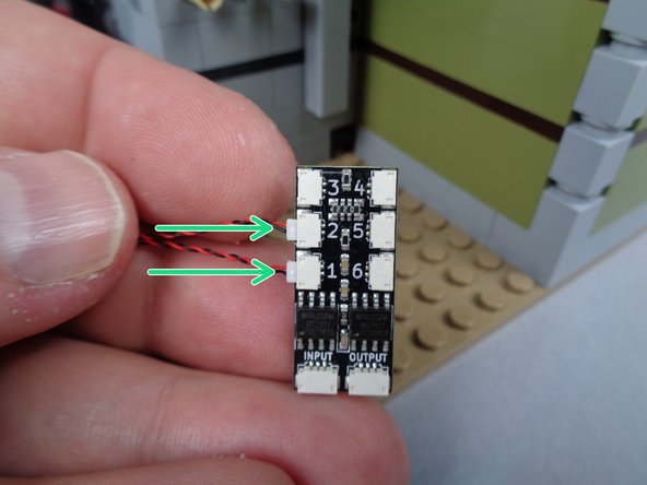
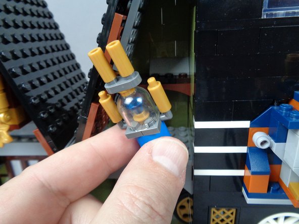
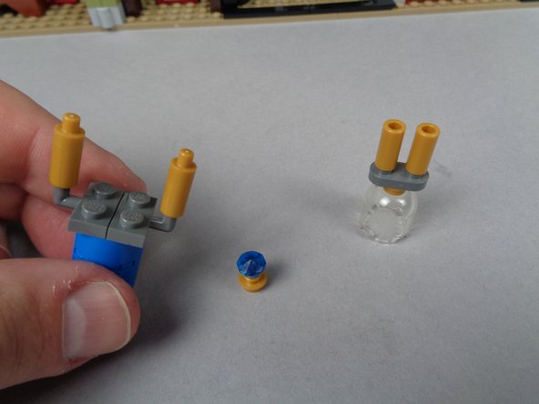
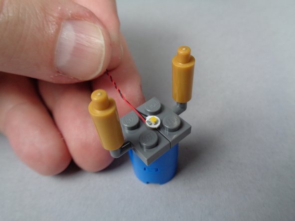

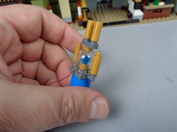

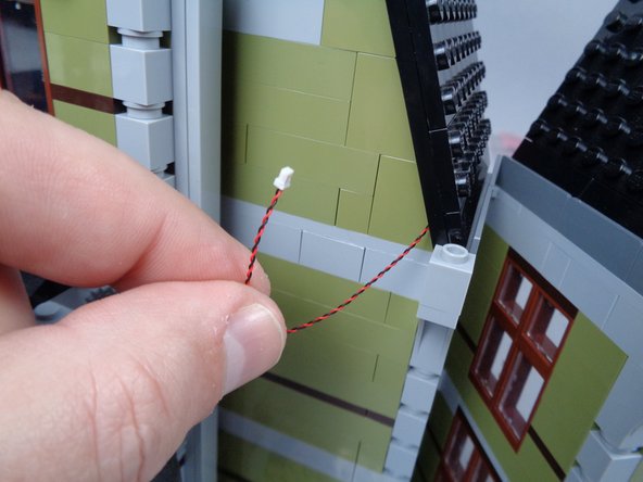
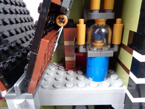
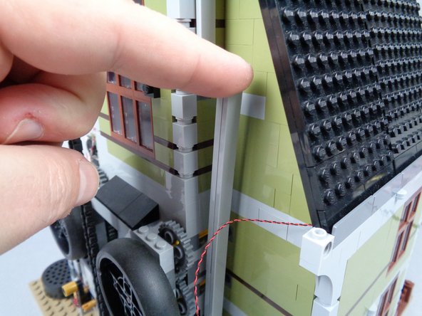
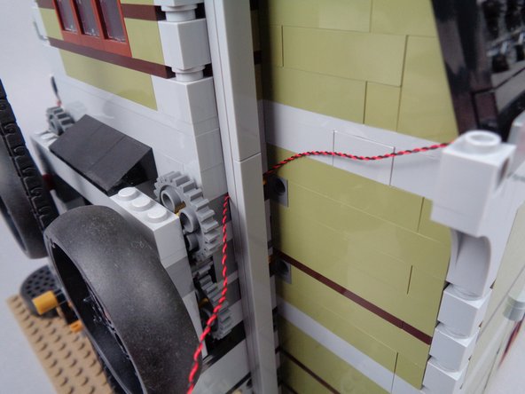
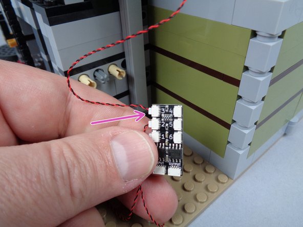
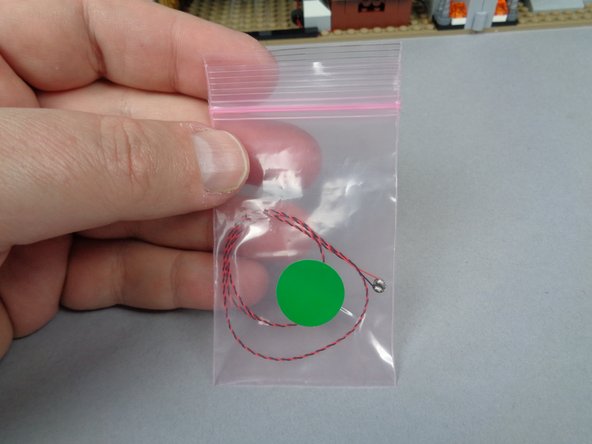

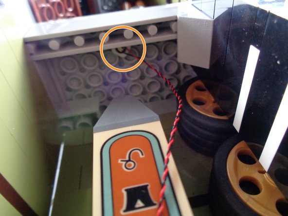
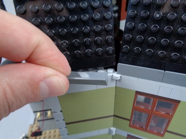
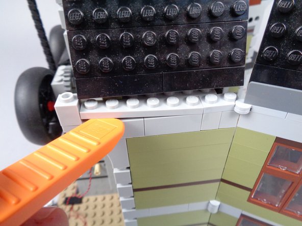

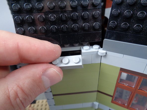
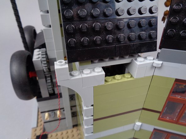
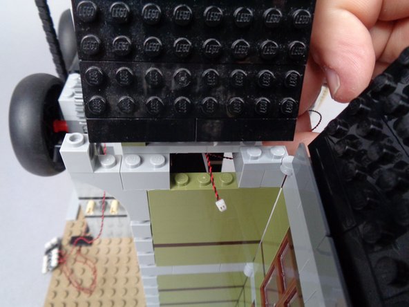
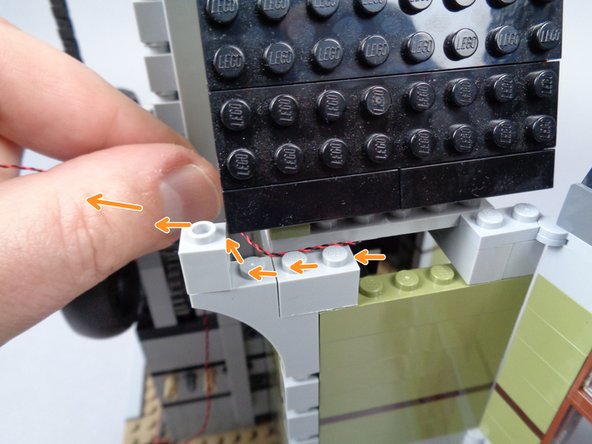

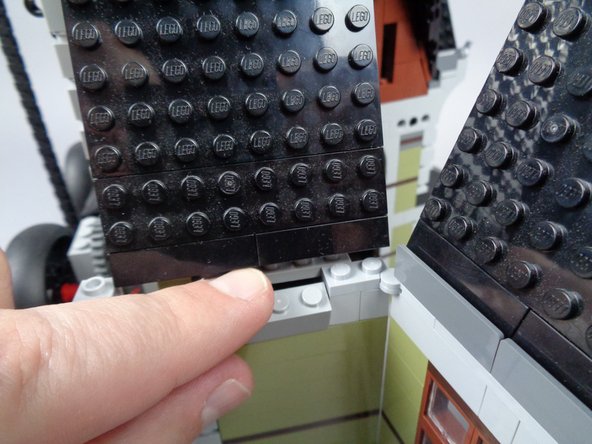
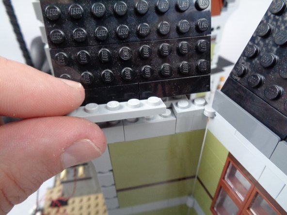
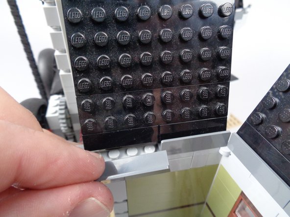
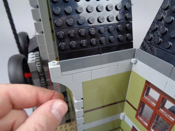
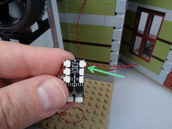
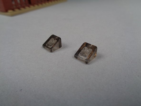
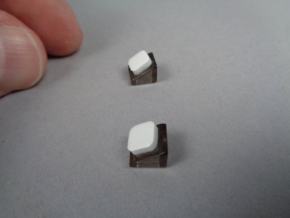
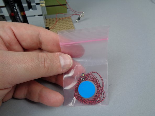
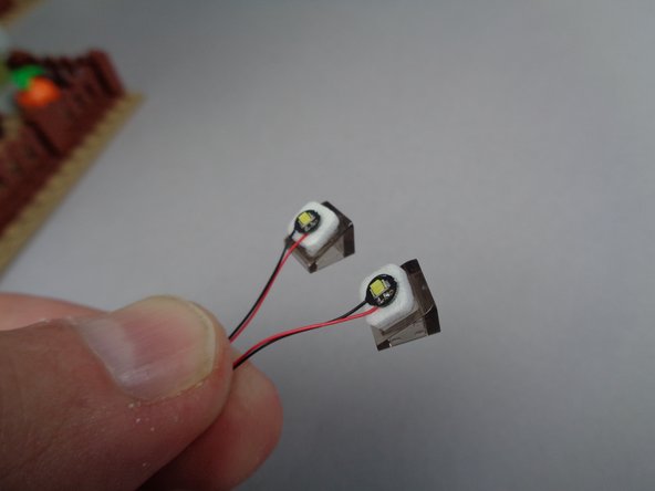
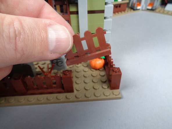
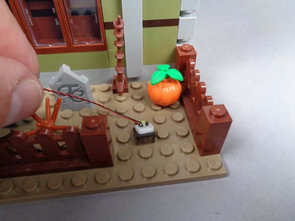
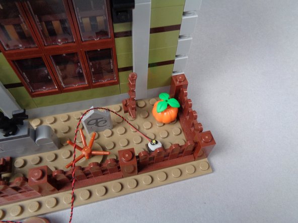
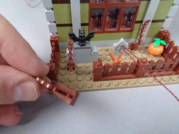
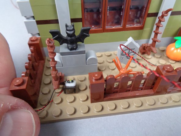
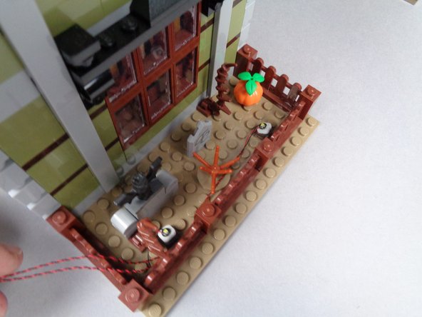

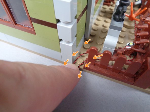
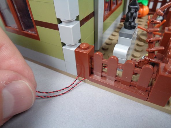

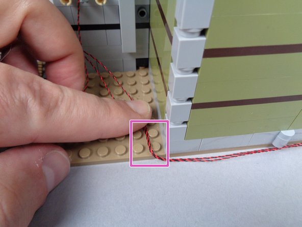
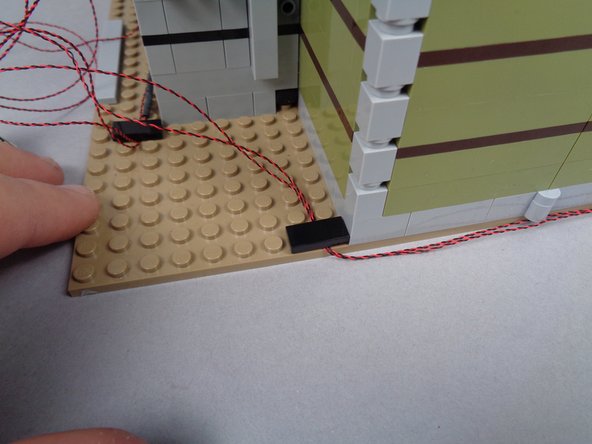
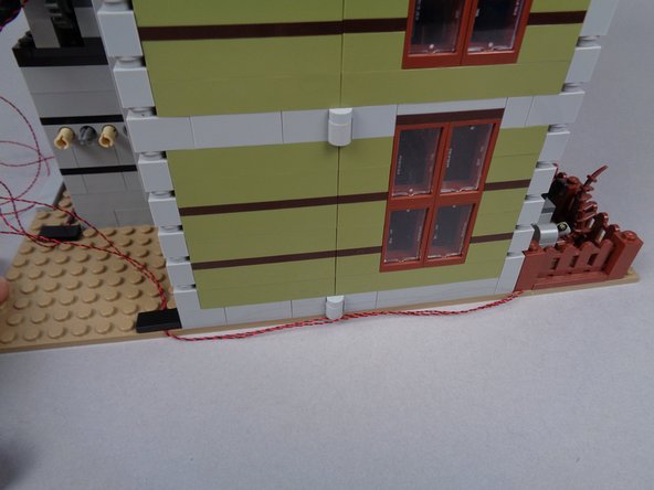
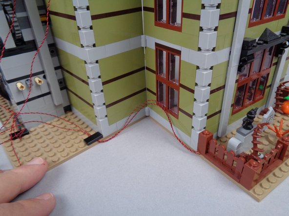
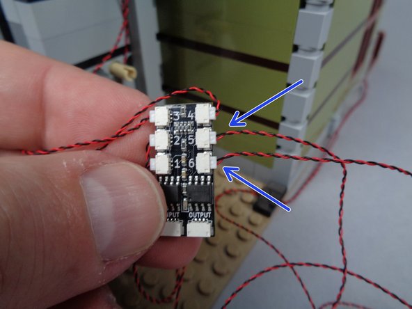

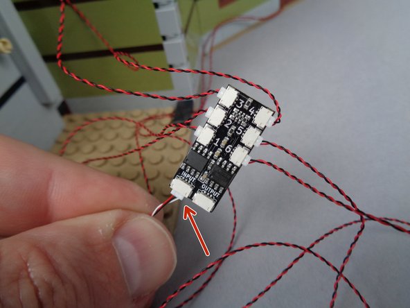
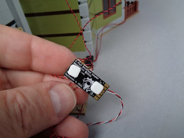
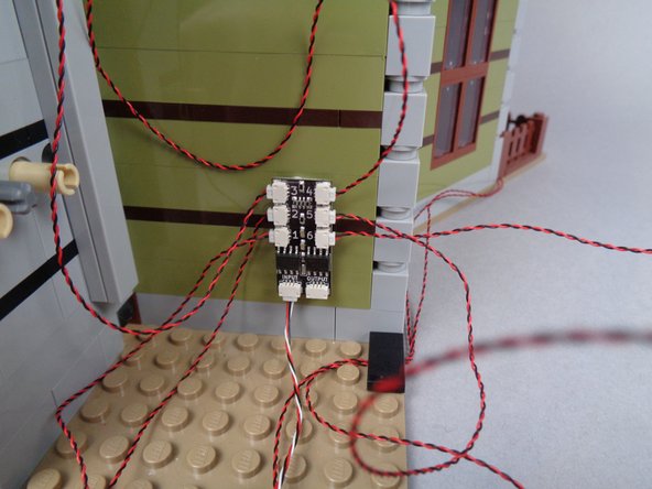
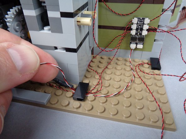
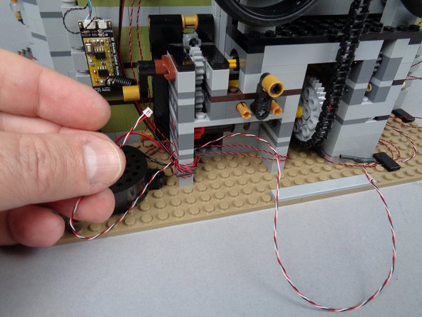
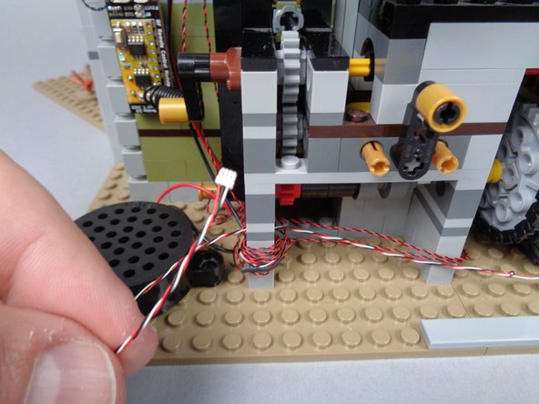
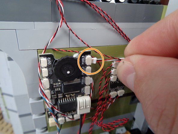
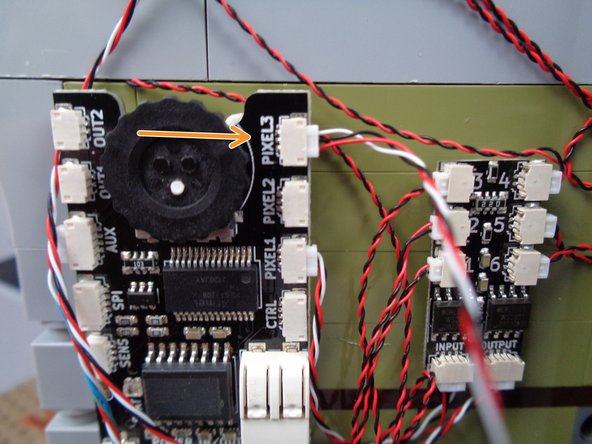
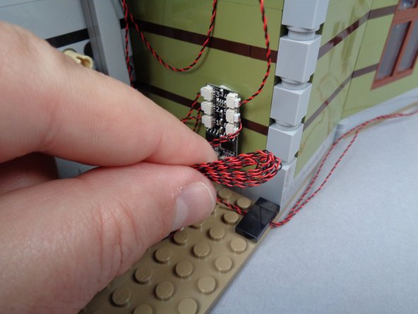
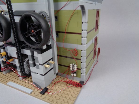
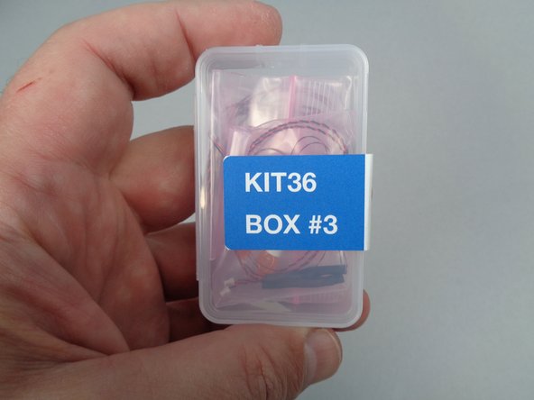
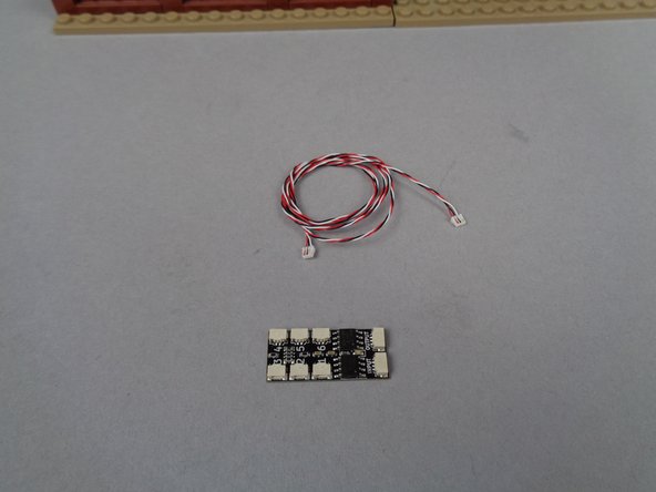
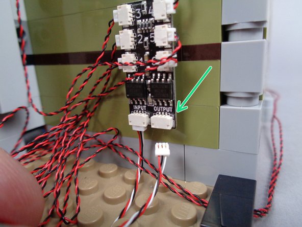
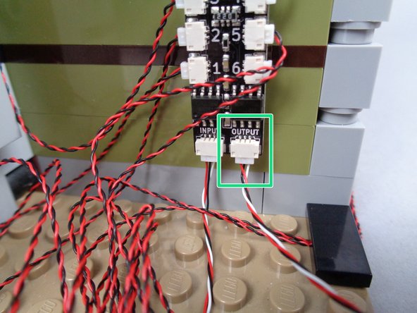
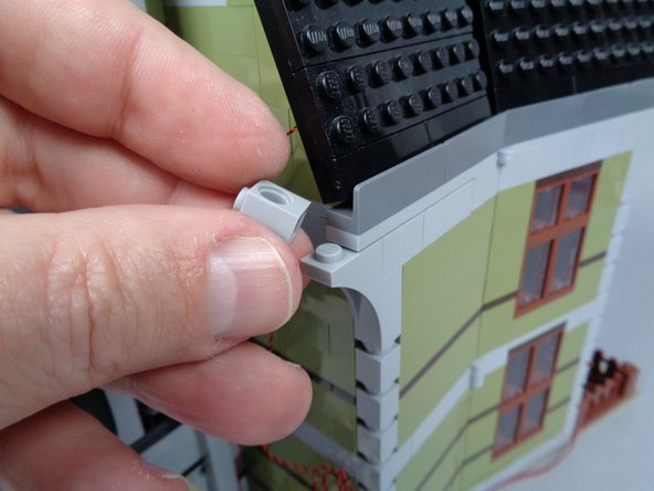
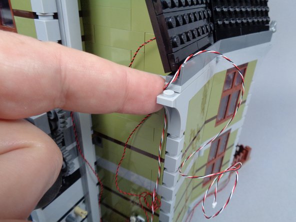
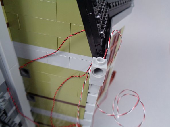
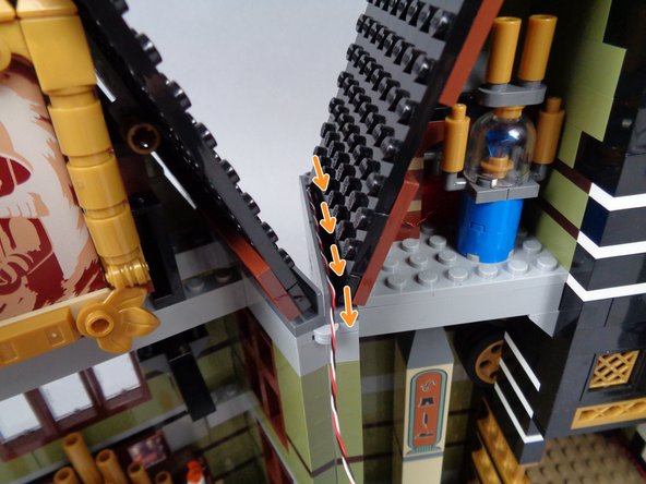
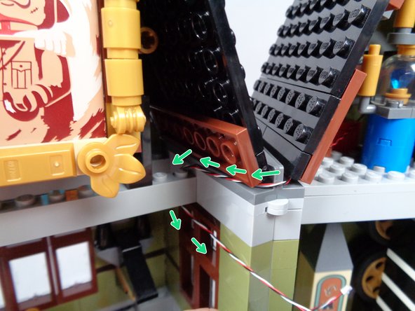
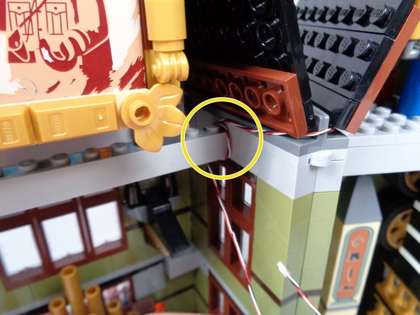
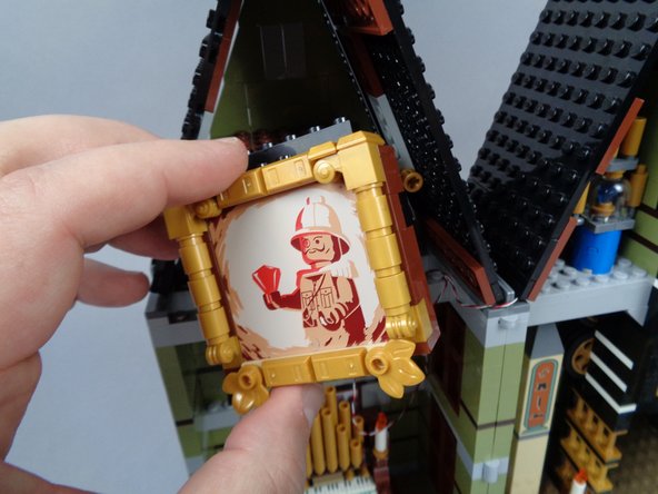
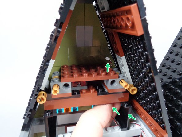
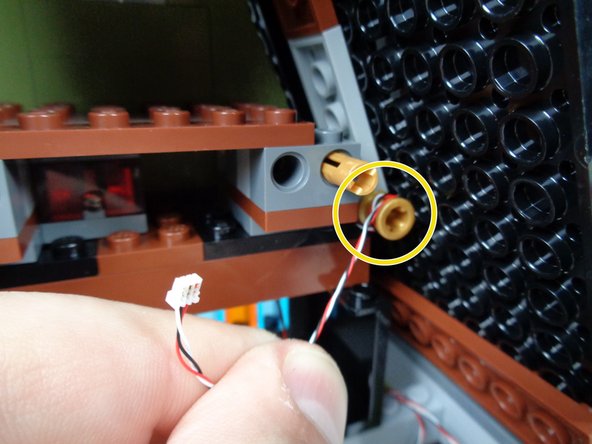
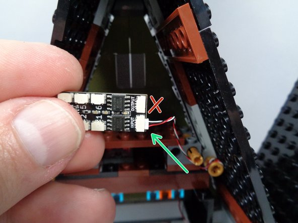

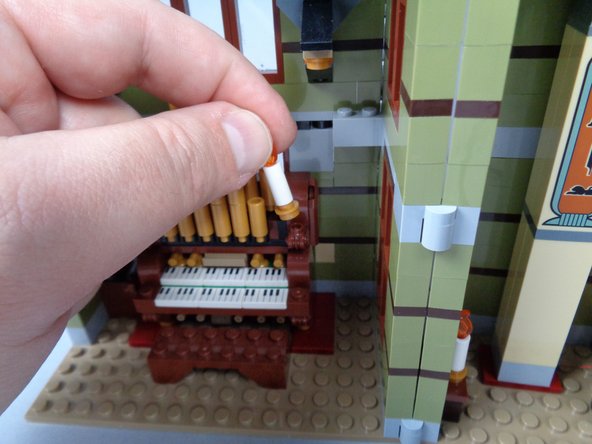
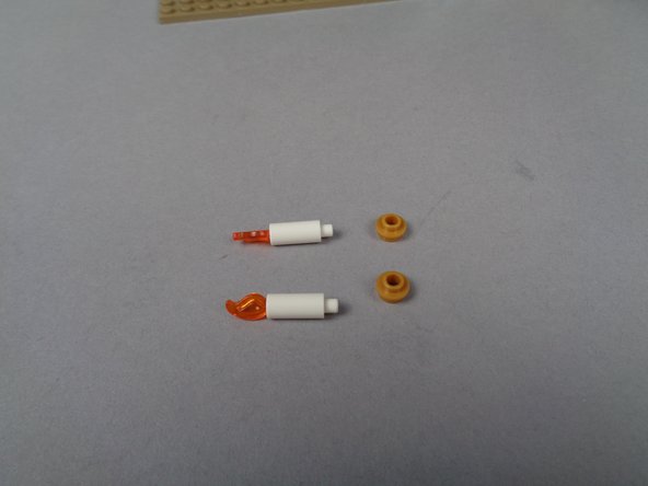
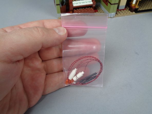

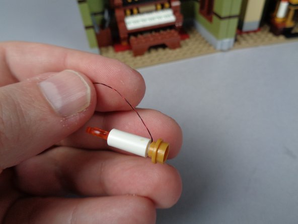
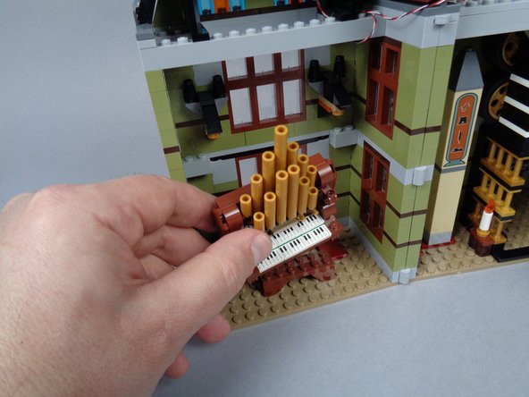
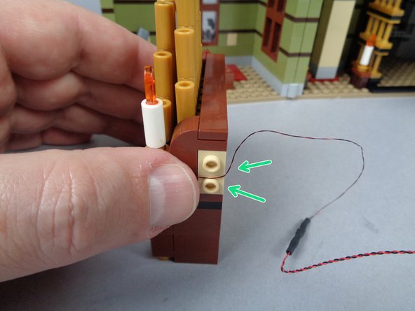
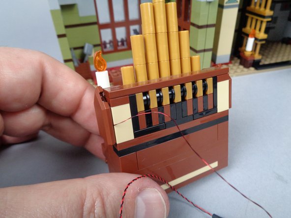
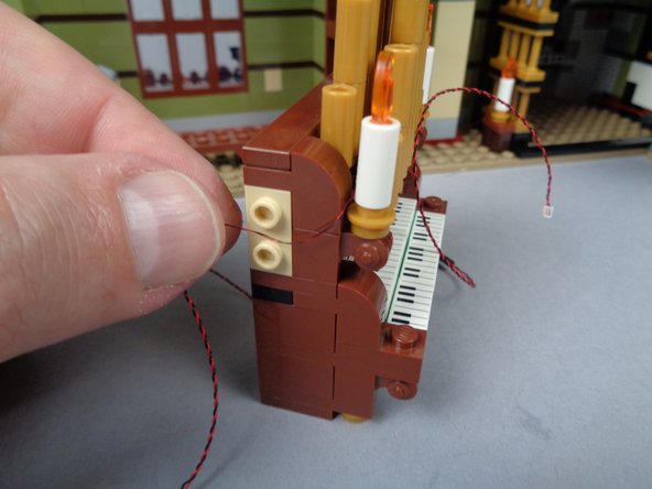
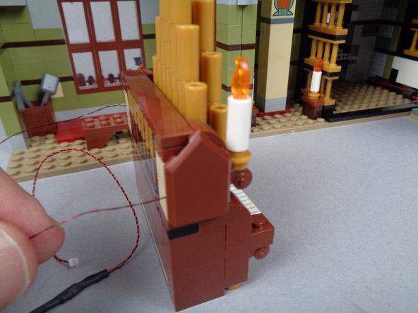

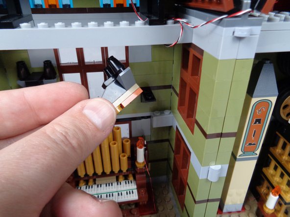
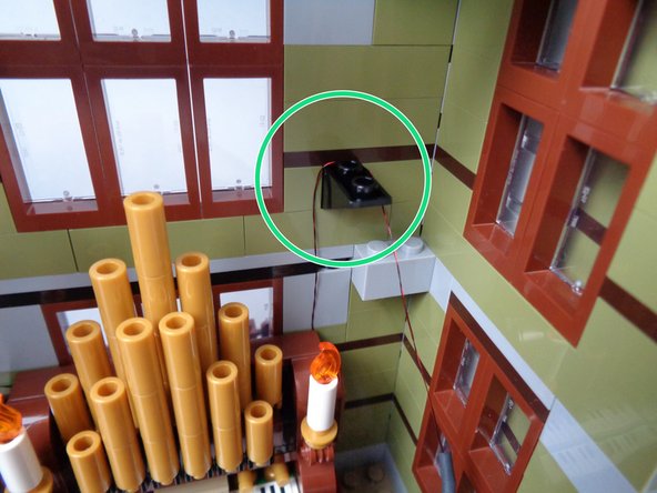
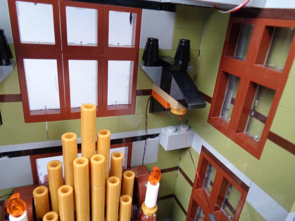
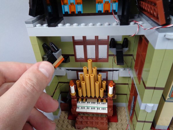
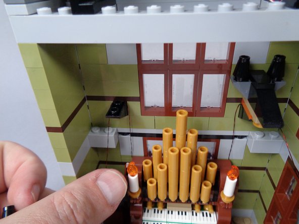
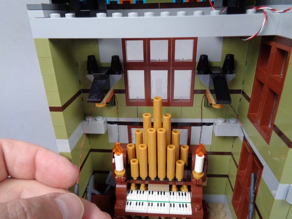

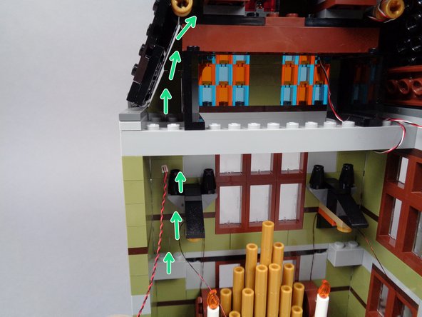
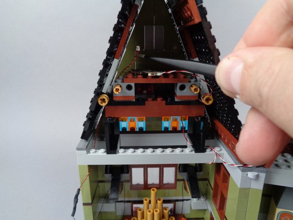
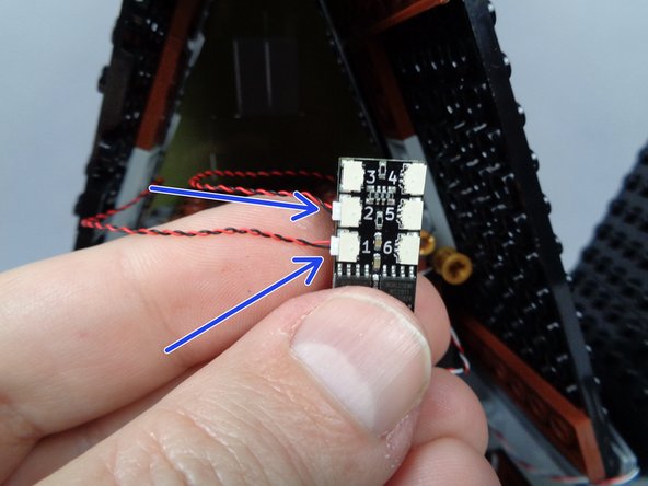
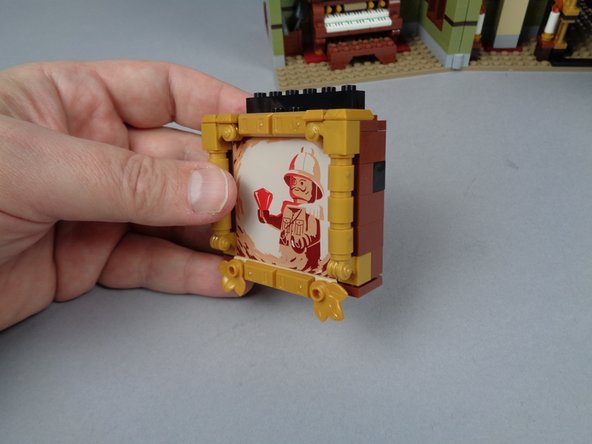

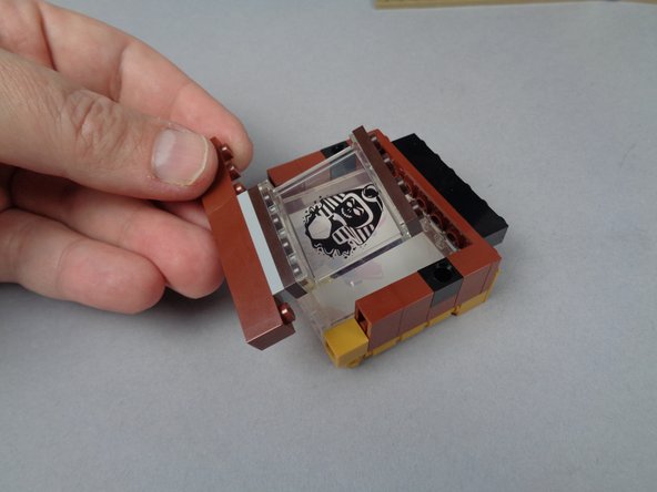
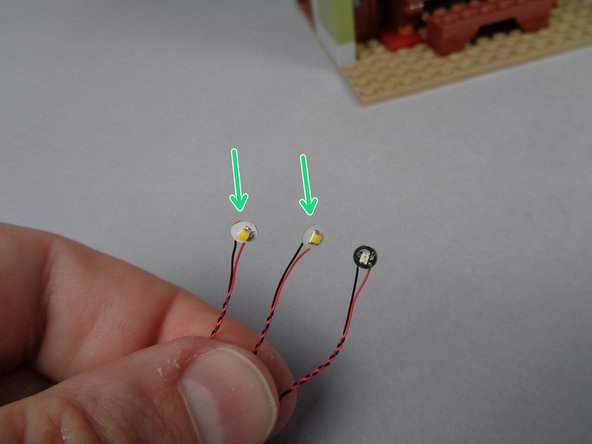
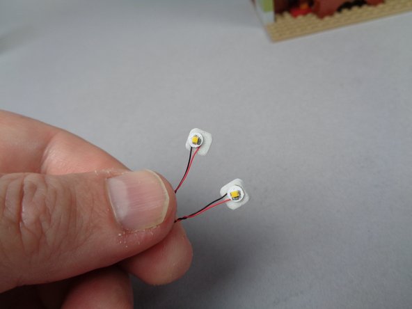

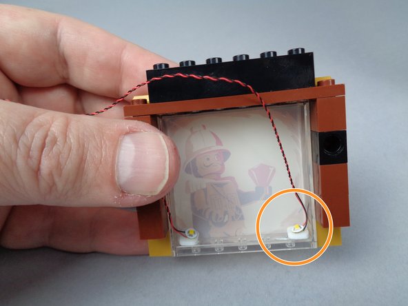
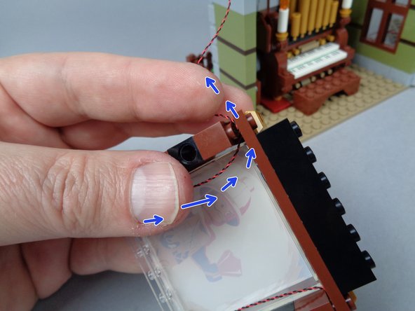
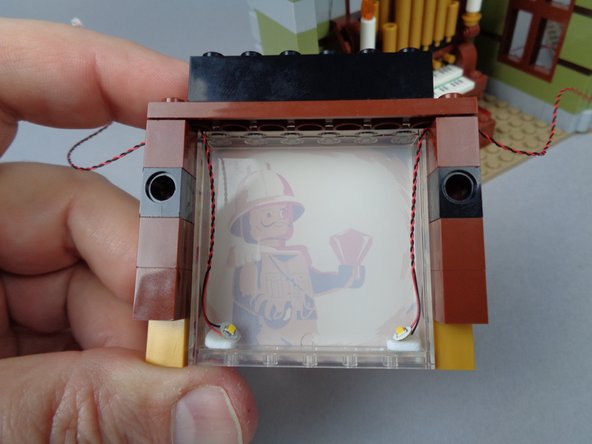
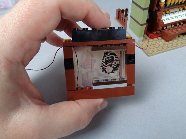
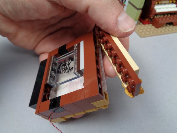

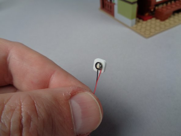
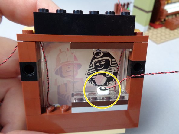
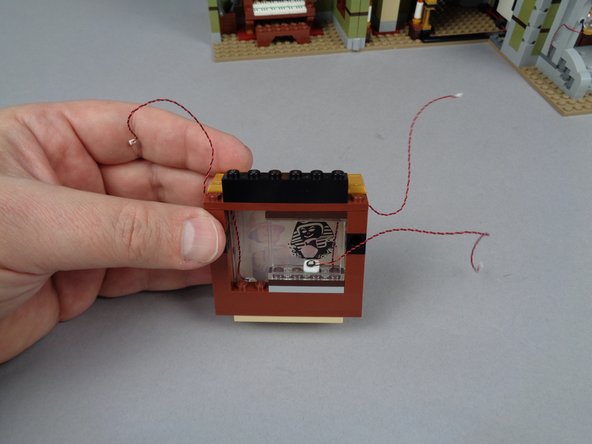
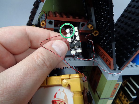
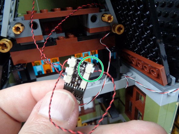

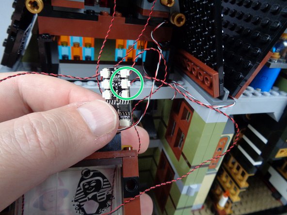
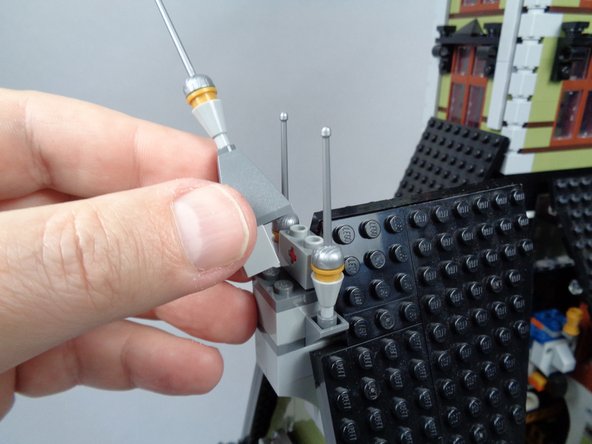
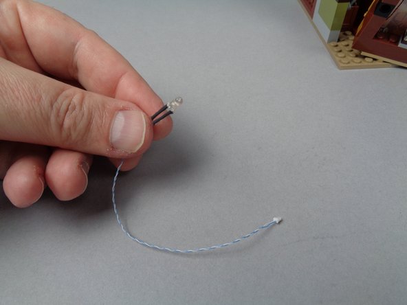
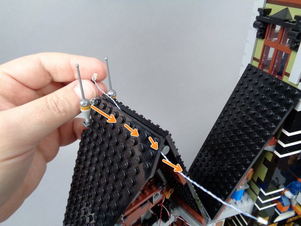
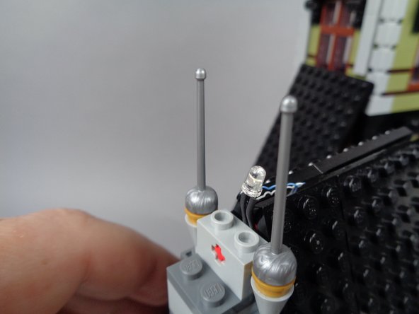
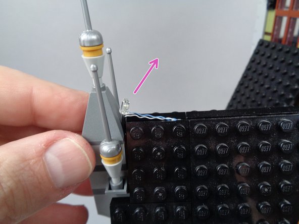
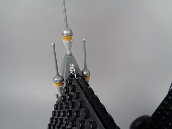
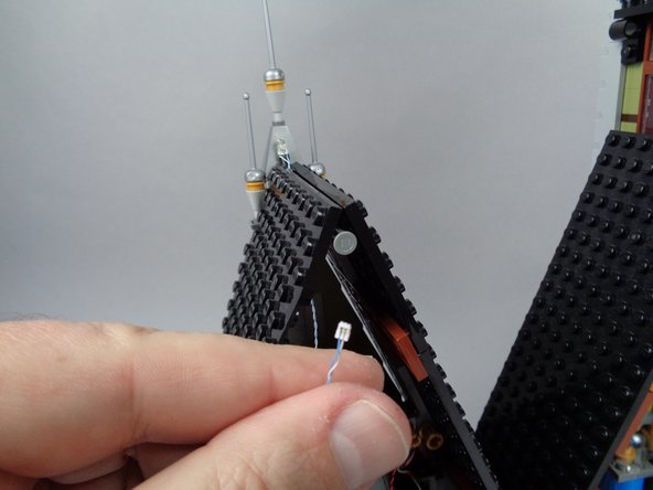
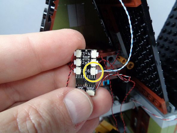
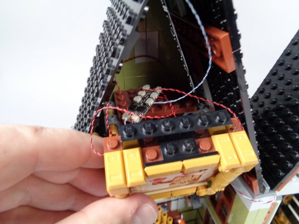
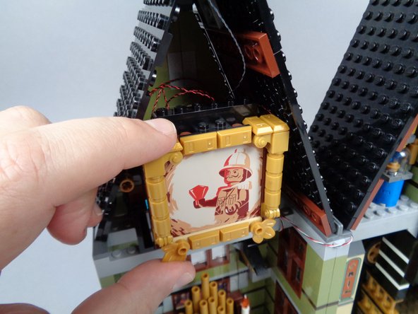

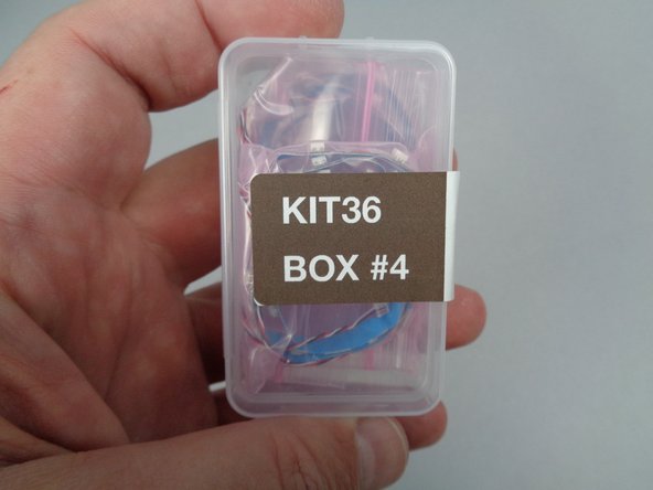
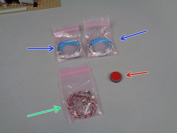
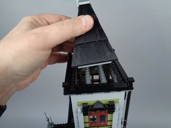
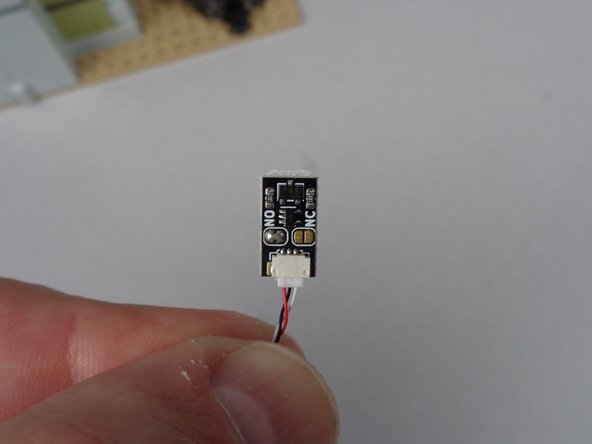
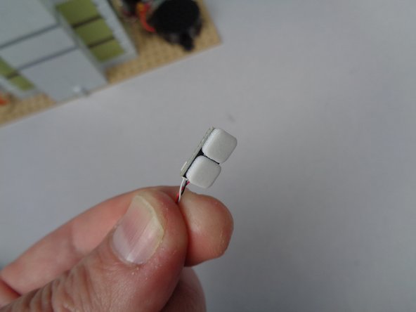
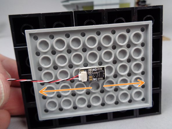
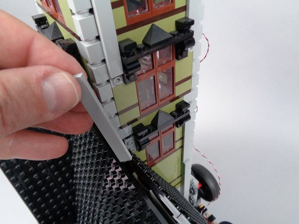
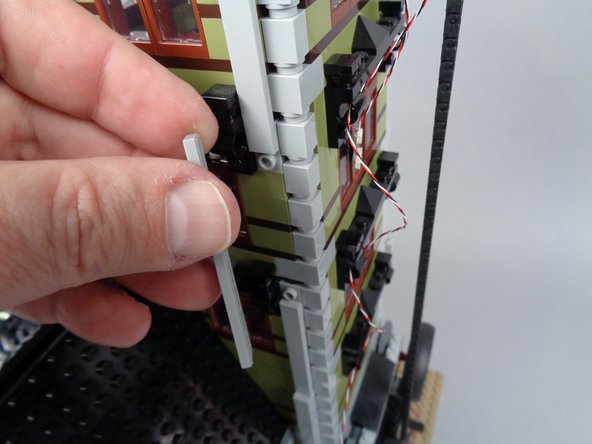
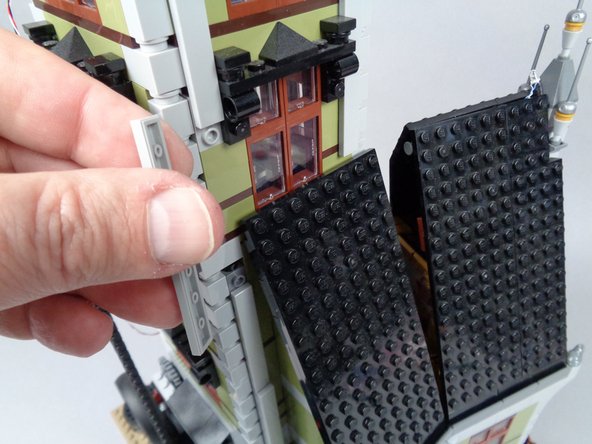
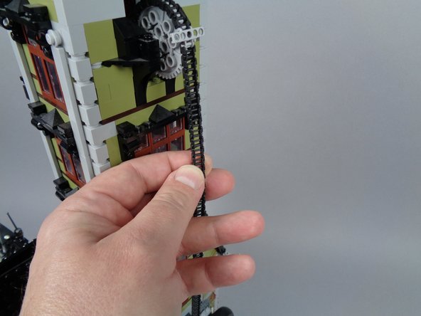
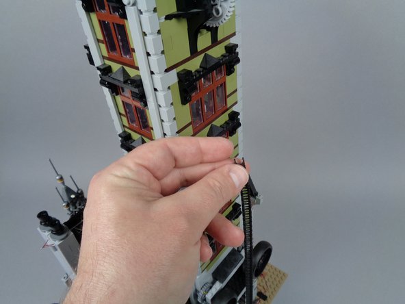
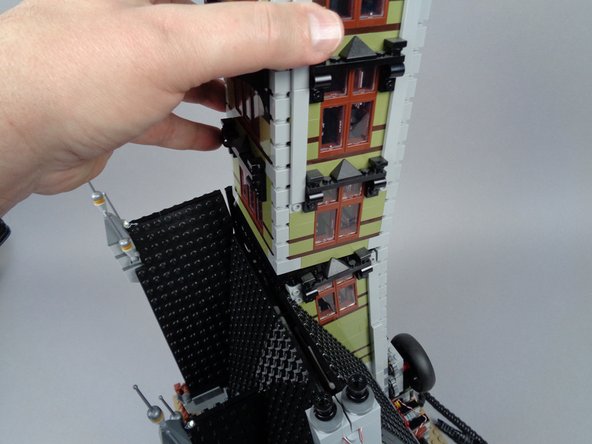
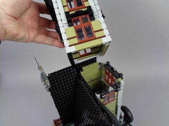
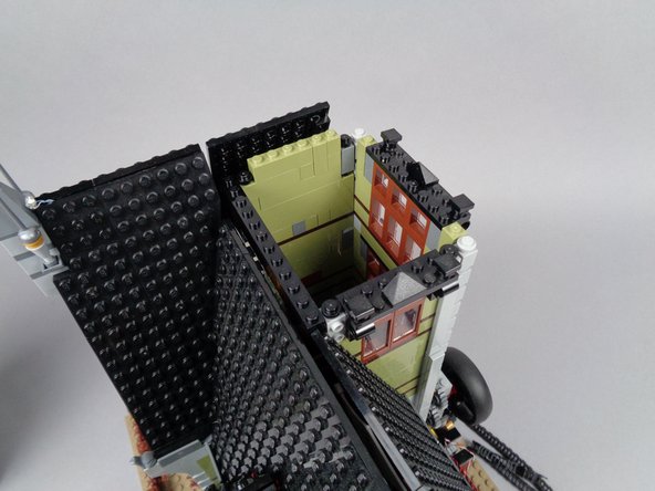
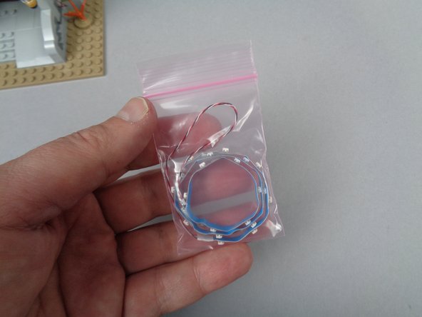
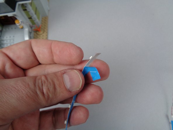
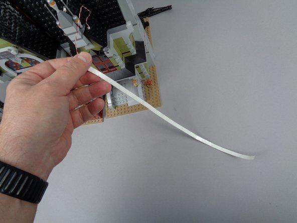
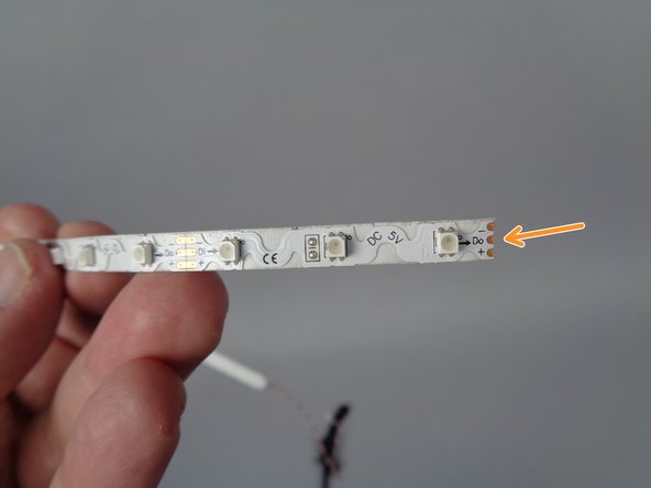
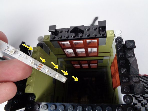
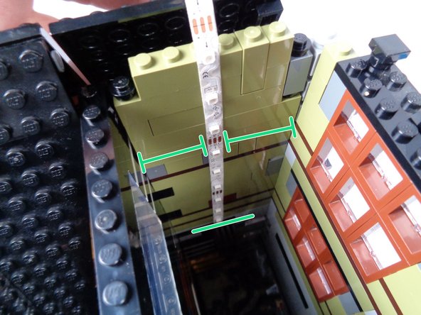
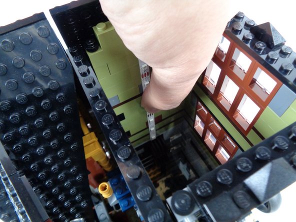
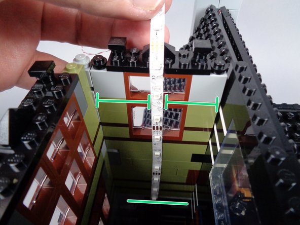
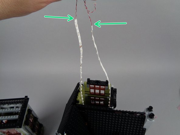

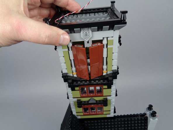

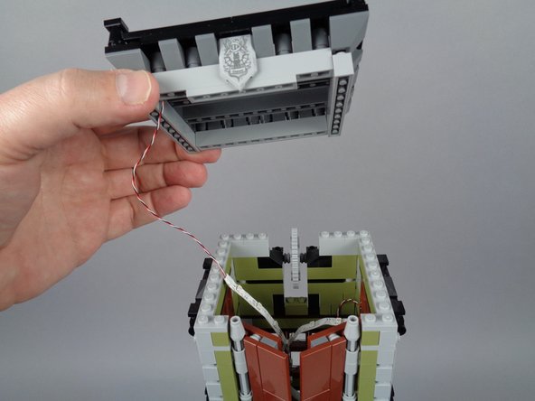
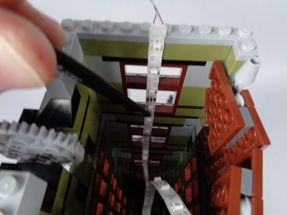
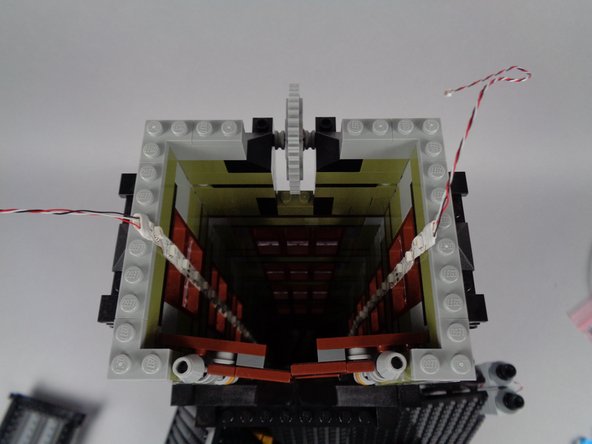
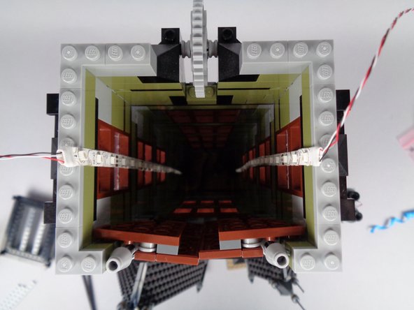
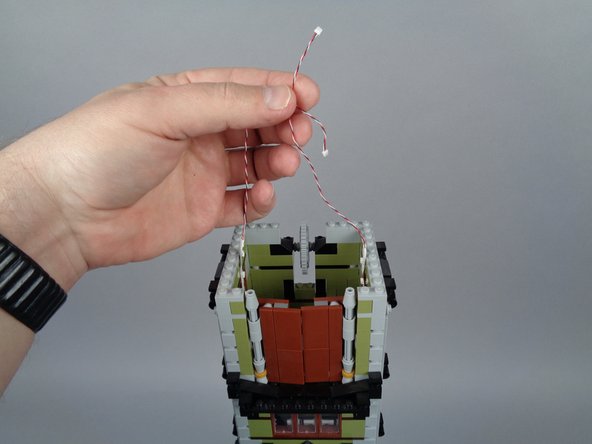
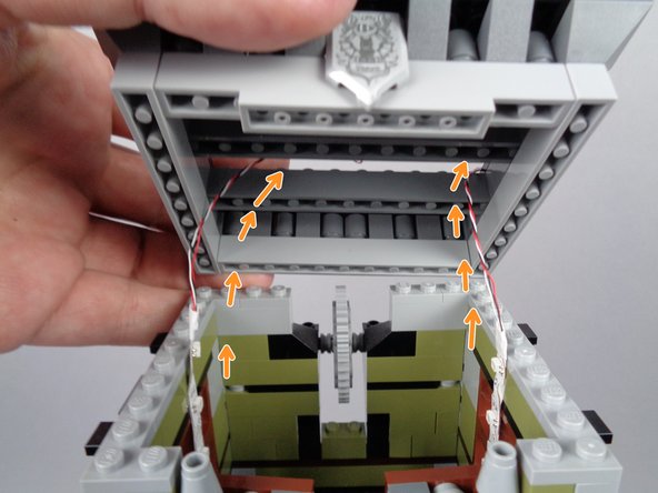
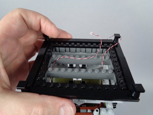

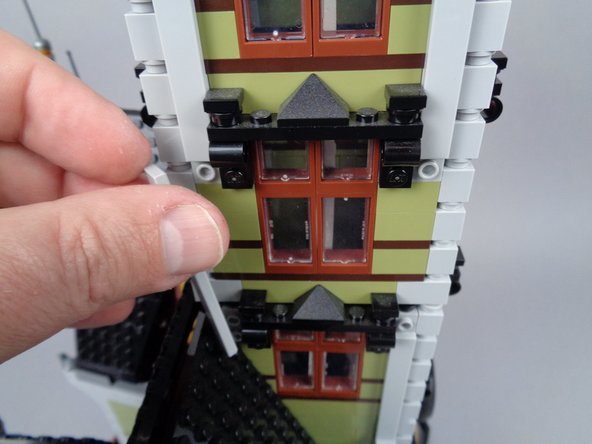
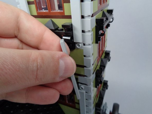
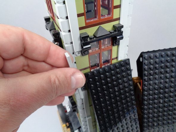
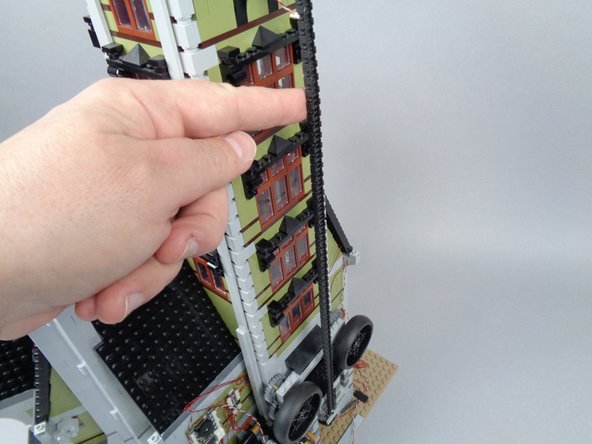
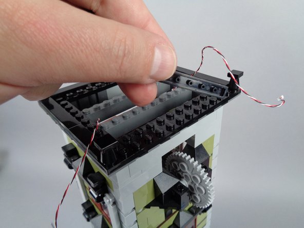
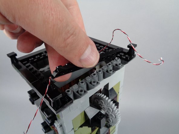
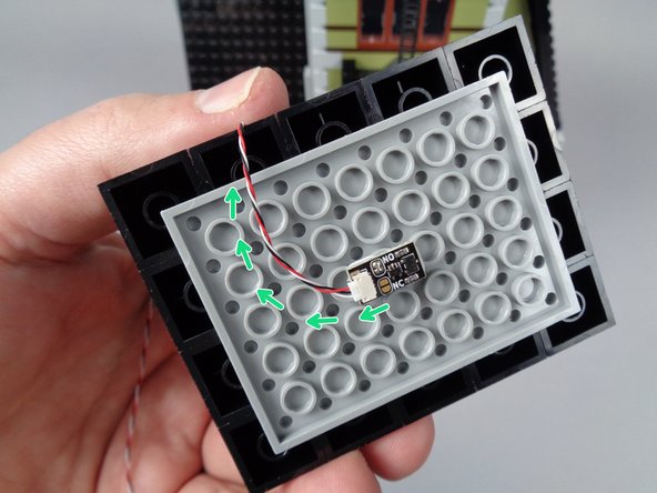
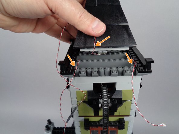
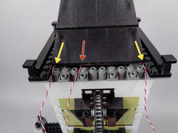
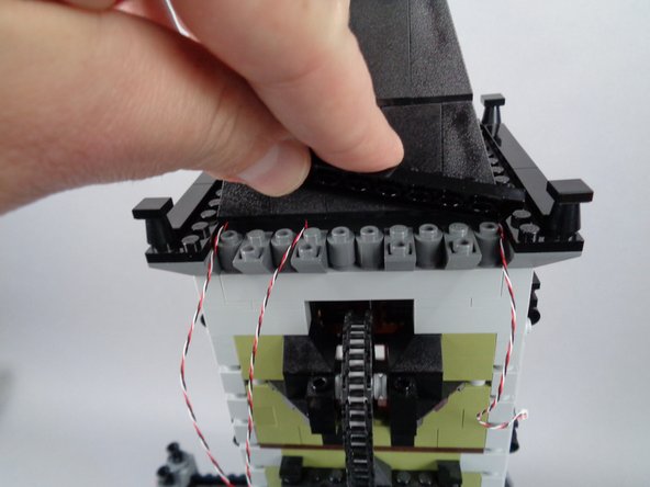
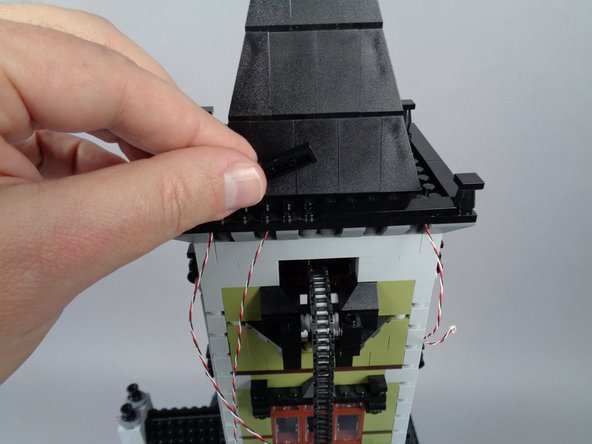
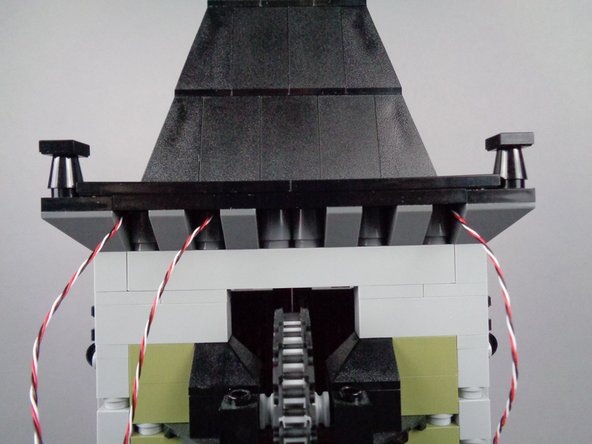
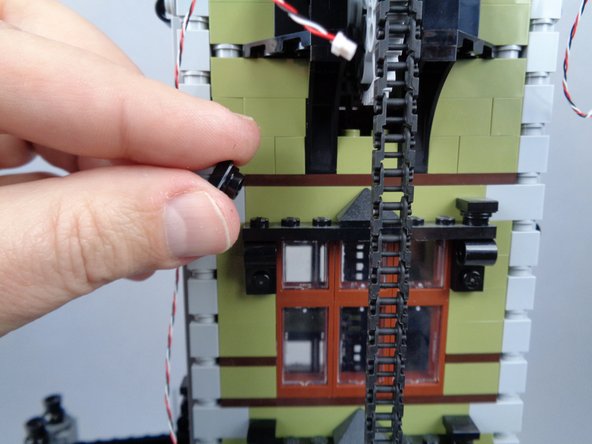
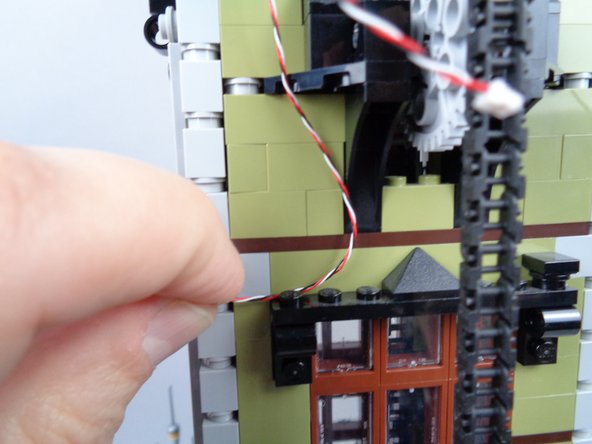
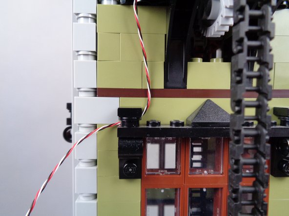
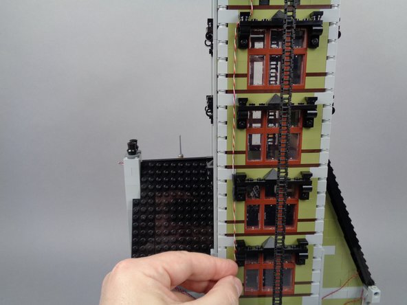
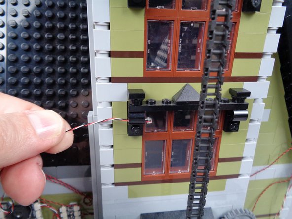
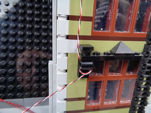
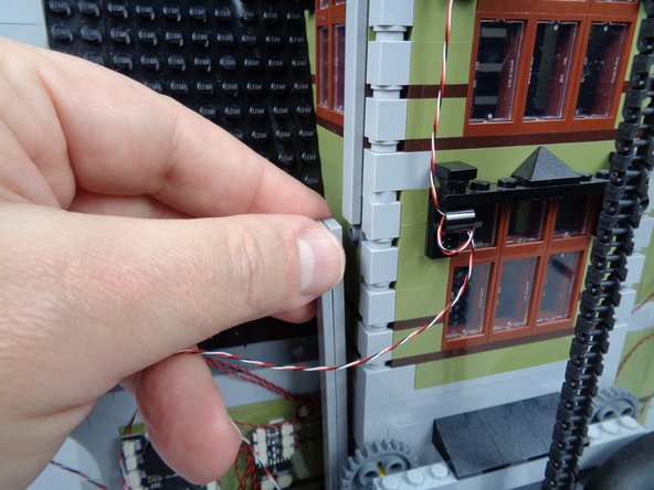
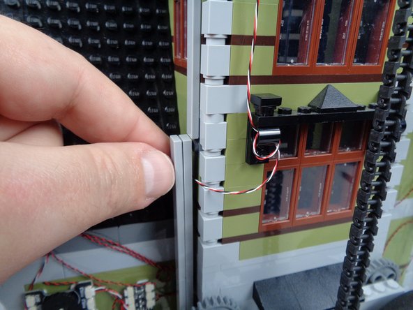
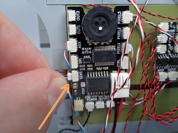
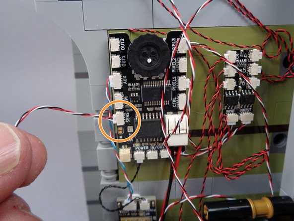
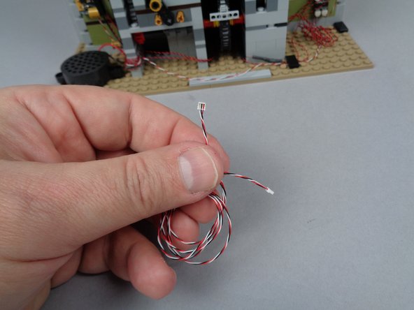
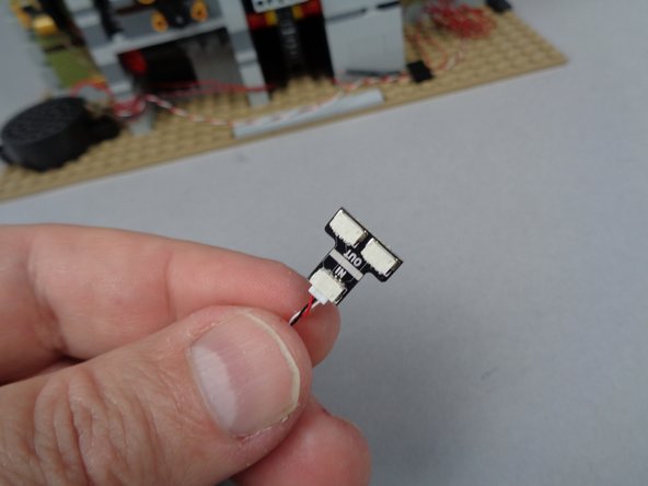

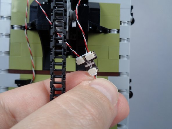
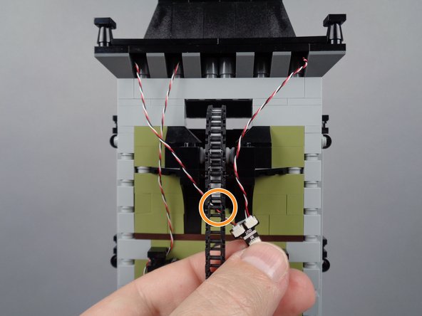
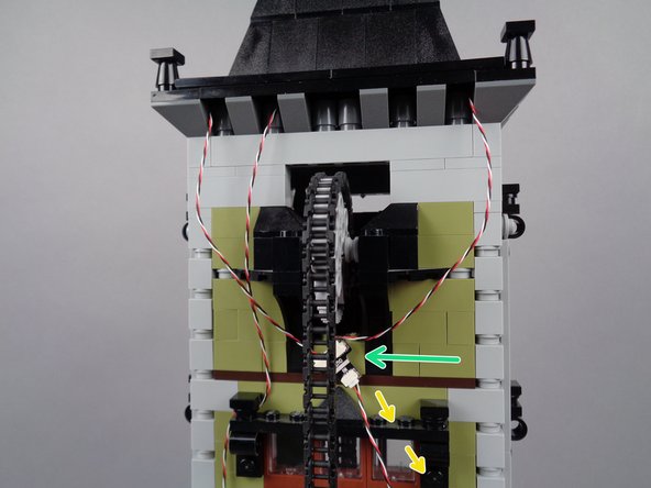
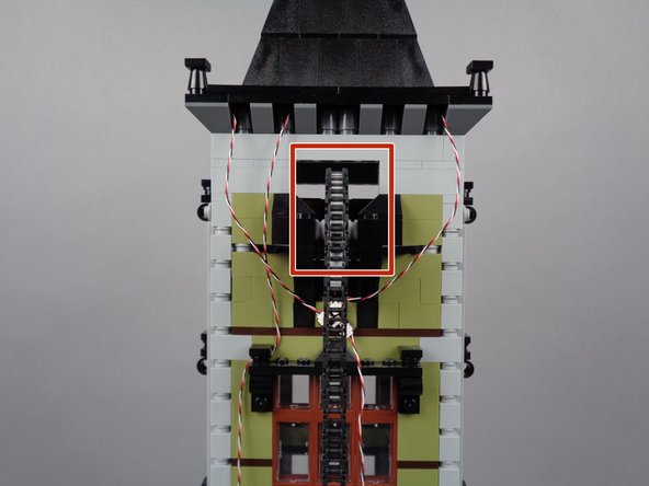
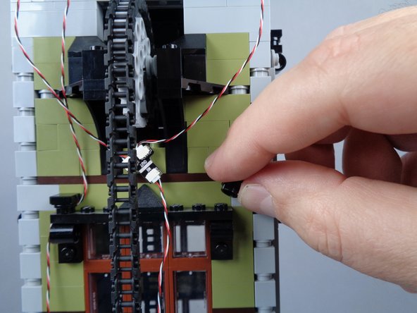
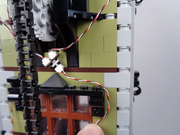
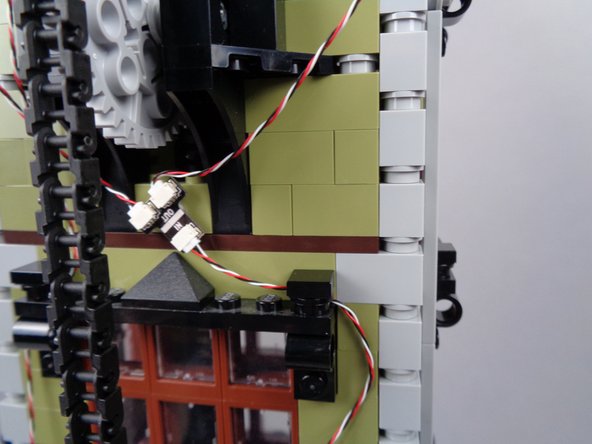
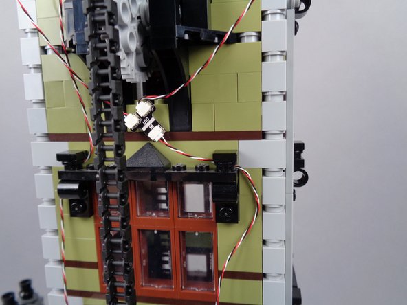
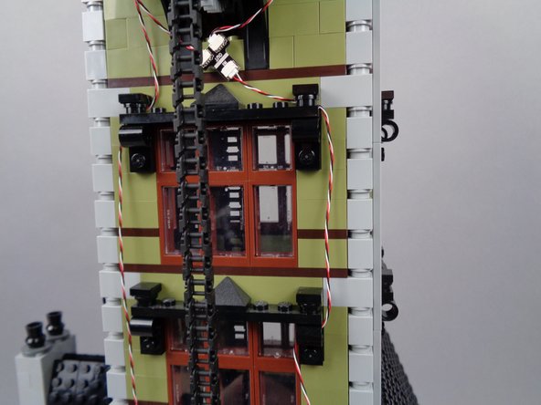
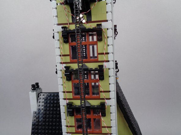
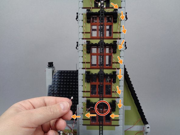
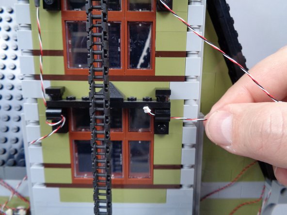
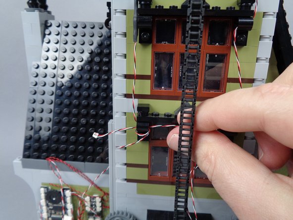
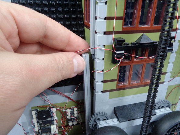
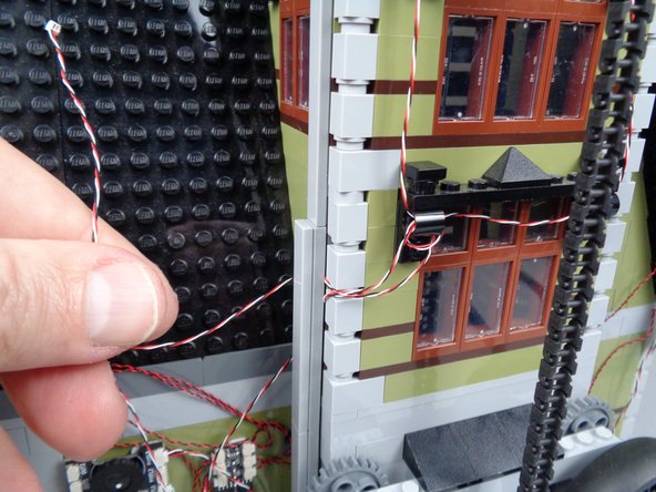
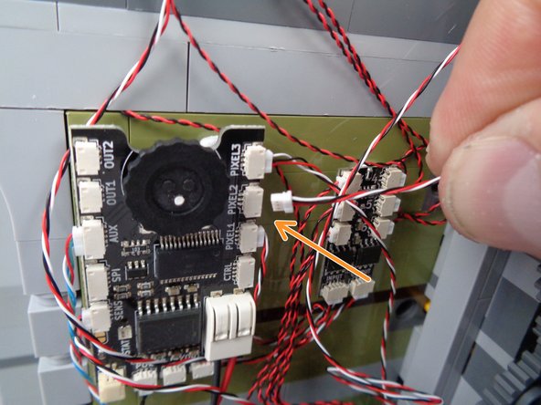
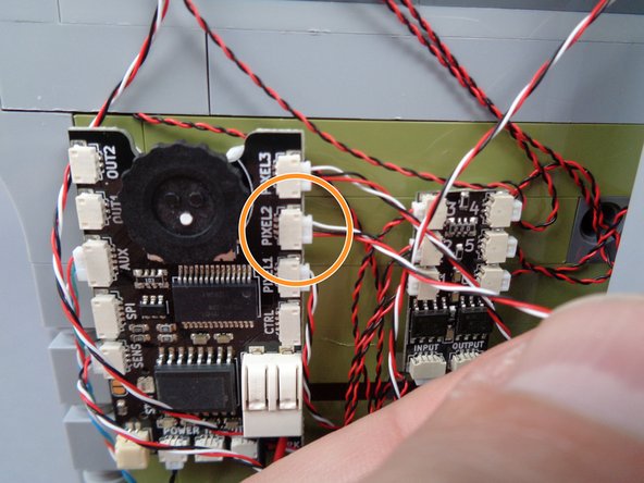
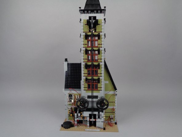
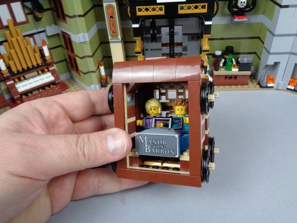
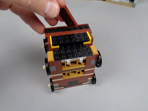

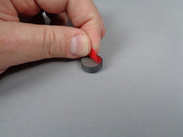
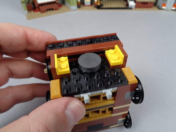
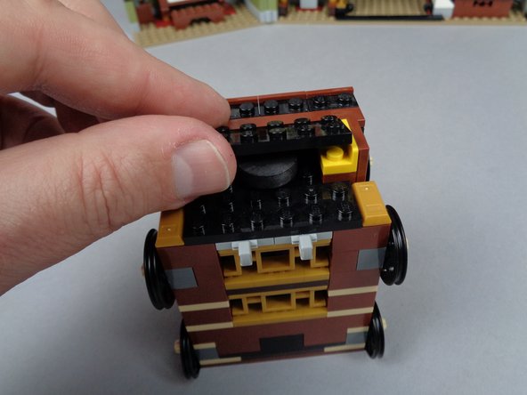
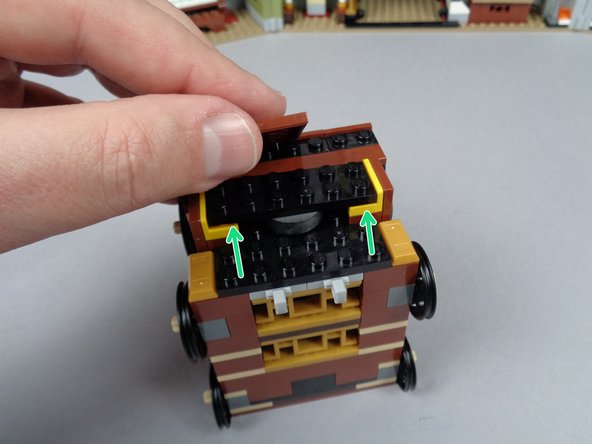
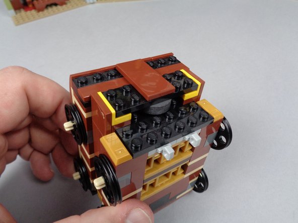
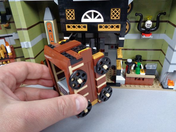
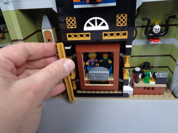
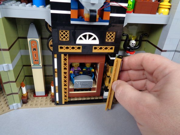

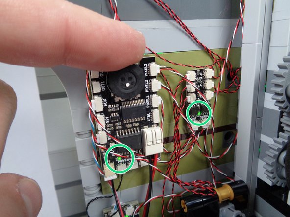
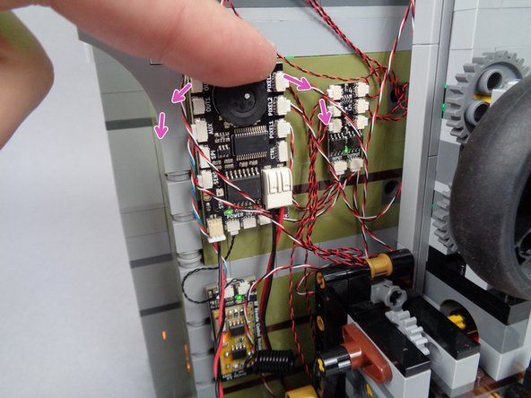
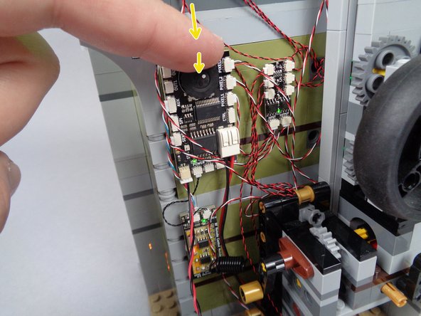
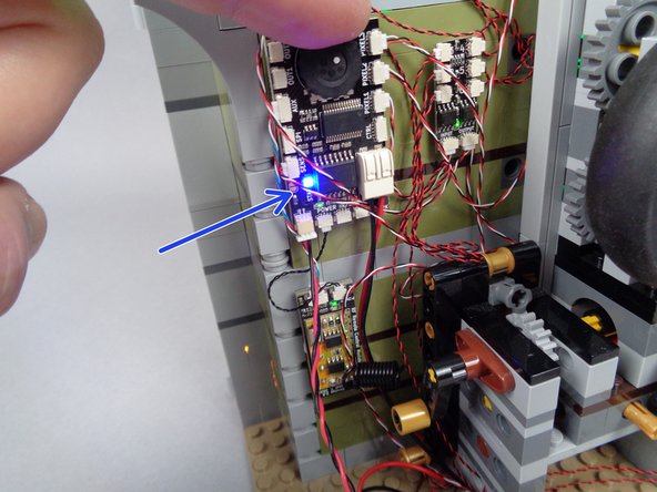
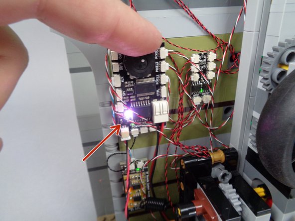
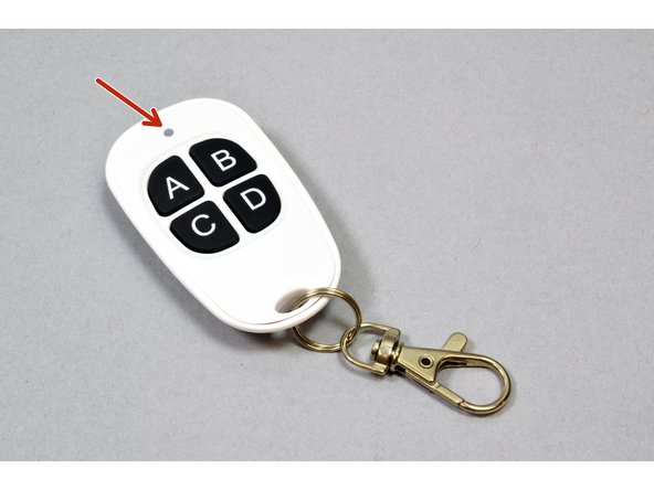
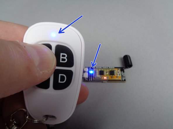
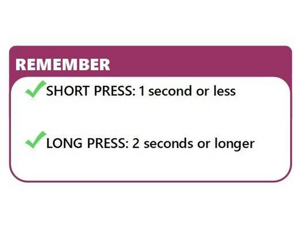

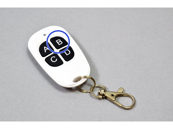
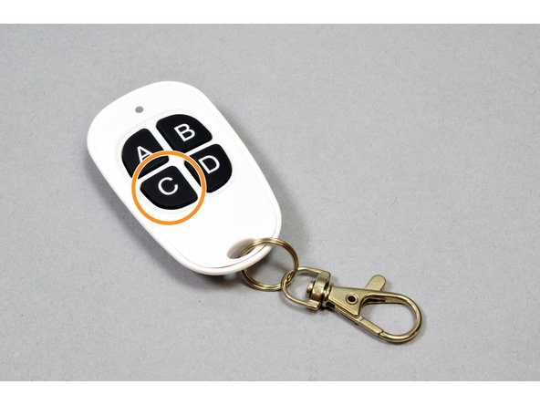
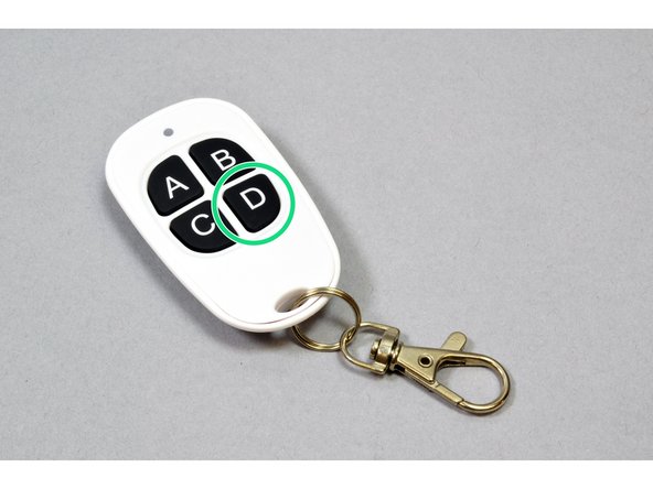
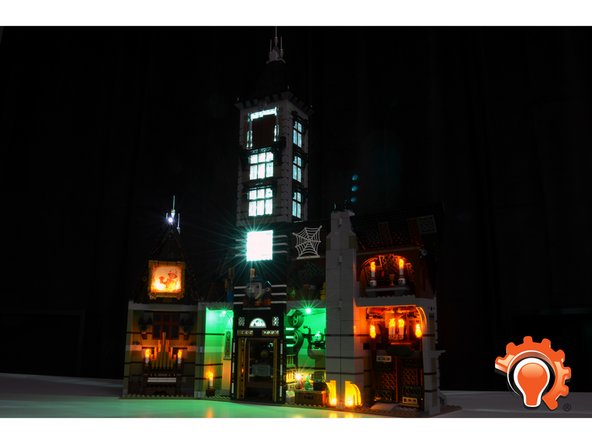
Attached Documents
