Tools
Parts
-
-
There are several ways to read this guide:
-
Reading it on the web in your browser.
-
Downloading a PDF copy of the guide. You can do this by selecting "Download PDF" as shown by the red rectangle in the first photo. Click on the Options heading in the upper right corner of the screen (see the green rectangle).
-
In the "Dozuki" application, which is available for download from the Apple App Store and various Android and Google marketplaces.
-
If you view this guide in the Dozuki app, search for "Brickstuff" the first time you open the app, then select "Product Guides" from the categories listed under Brickstuff. Scroll down to find this guide.
-
You can also translate this guide into another language when viewing on the web. To do this, install a translator extension into your browser and use that extension/plug-in to translate the page. Using the main Google translate website (translate.google.com) does not work.
-
-
-
Begin by removing the top of the head from your Raider as shown in the first photo for this step.
-
As shown in the second photo, remove the parts around the round eye ring.
-
As shown in the third photo, remove the round transparent red eye ring from the head.
-
-
-
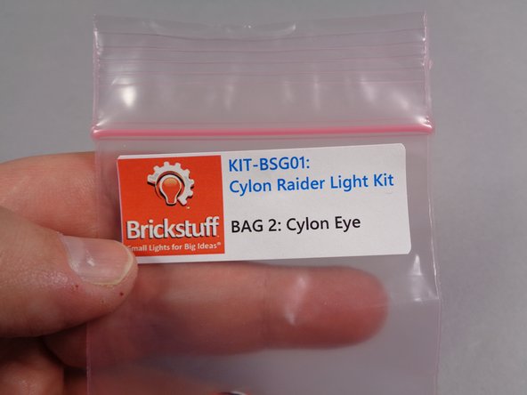
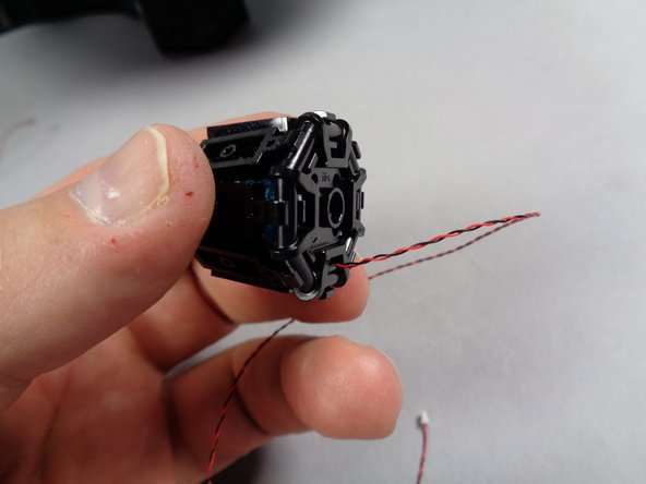
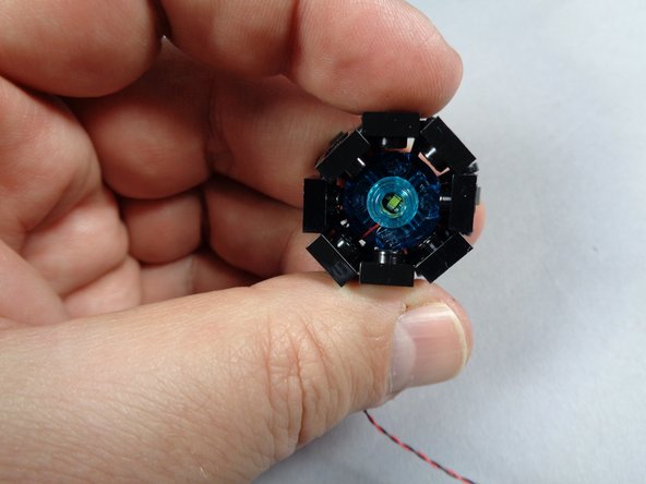
Remove the pre-lit eye assembly from Bag 2 as shown in the first photo for this step.
-
The eye assembly is extremely fragile-- do not disassemble it! The parts have been glued together and the LED lights inside have been aligned and tested. Excessive handling of the eye section will damage the electronics inside. A damaged eye section cannot be repaired.
-
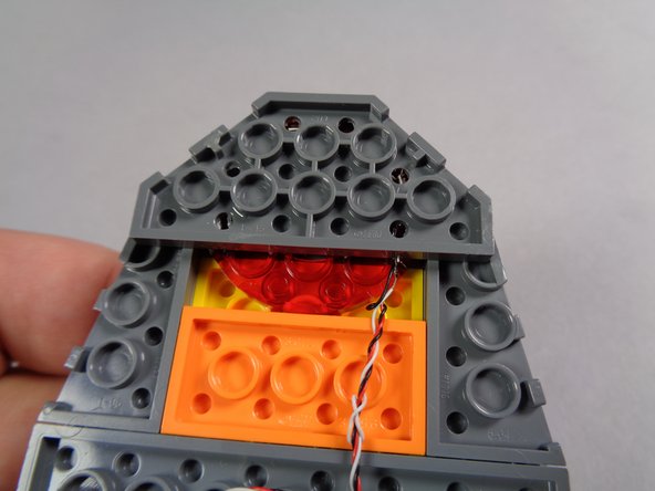
As shown in the second photo for this step, carefully press the pre-lit eye section into the head.
-
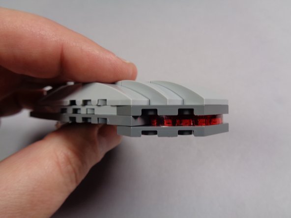
When you have finished attaching the pre-lit eye section, your head should look like the third photo.
-
-
-
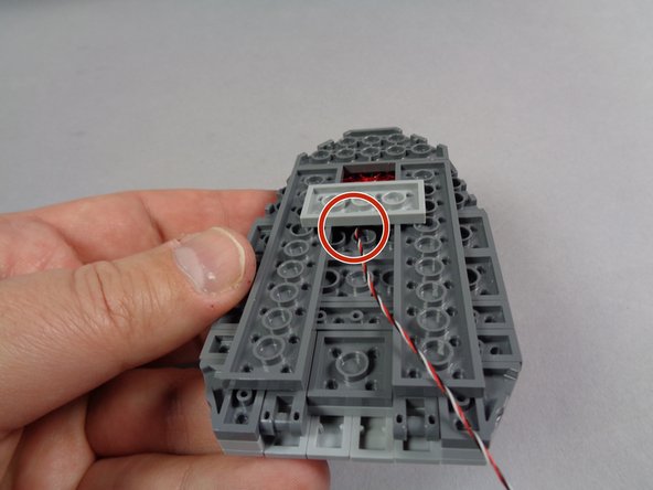
As shown in the first photo for this step, carefully begin re-attaching the parts that hold the eye in place.
-
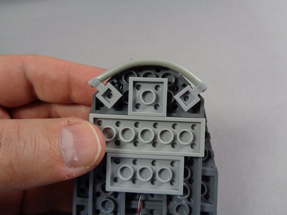
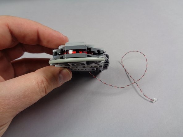
The red circle in the first photo shows how the control wire for the eye assembly should pass UNDERNEATH the light bluish gray 2x4 plate. Make sure the wire is never pinched between studs.
-
Re-attach the remaining lower head parts as shown in the second photo.
-
You should now have a fully re-assembled head section as shown in the third photo.
-
-
-
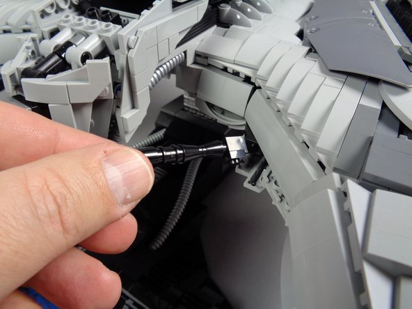
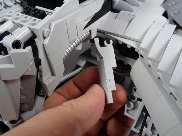
Next you will remove the two front guns as shown in the first two photos for this step.
-
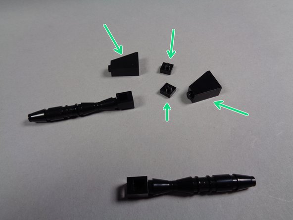
As shown by the green arrows in the third photo, separate these four parts from the guns and keep them. You can set aside the old guns.
-
-
-
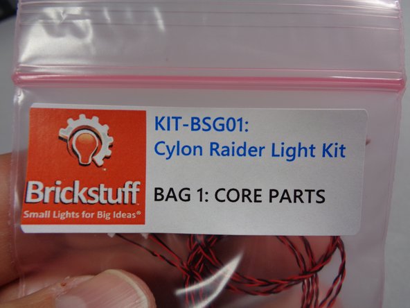
Next you will remove the two replacement guns from Bag 1 (shown in the first photo).
-
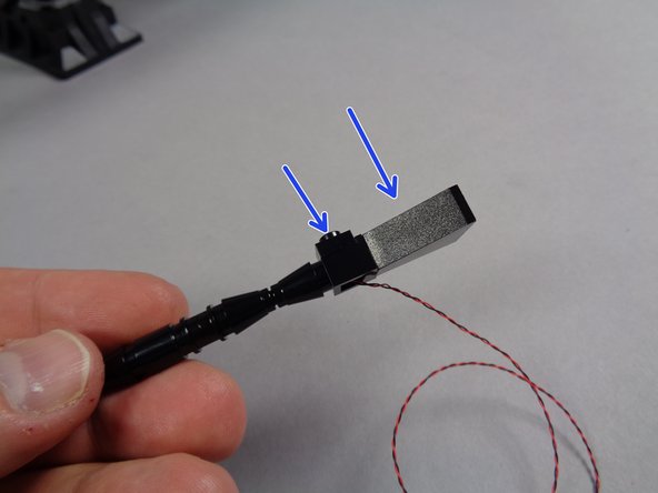
As shown by the two blue arrows in the second photo, re-attach the 1x1 black plate and the black slope to the replacement guns. Do this for both the left and the right gun.
-
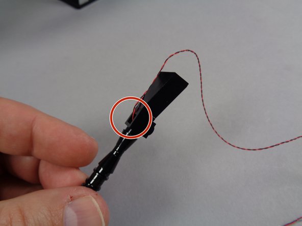
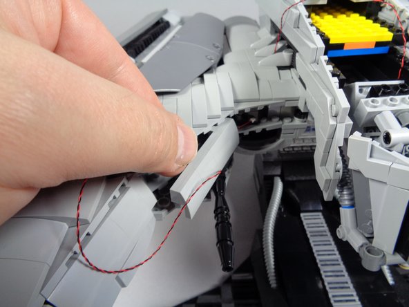
As shown by the red circle in the third photo, make sure the wires for the LED lights inside the guns pass through the bottom hole in the black headlight brick as shown. Make sure the wires are not pinched on top of any parts.
-
-
-
As shown in the first photo for this step, remove the front armor section to the right of the head section.
-
As shown in the second photo re-attach the right gun.
-
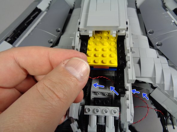
As shown by the blue arrows in the third photo, carefully pass the light wire toward the head, up through the opening in the bottom of the head, and into the main head section. Make sure the wire passes under the chin.
-
-
-
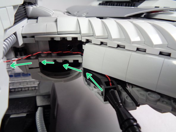
As shown by the green arrows in the first photo for this step, carefully pass the light wire behind the armor section just above the gun, to hide the wire.
-
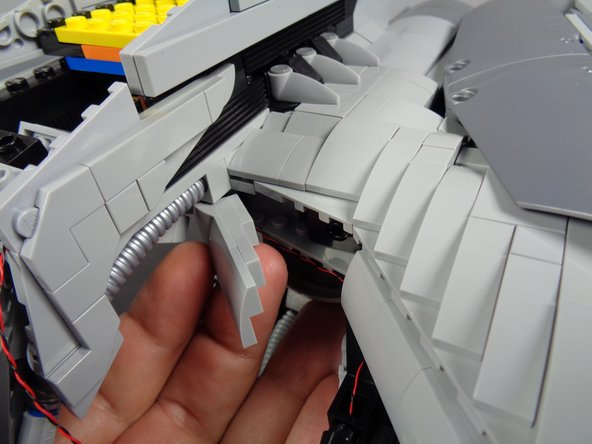
As shown in the second photo, re-attach the armor section you removed in the last step.
-
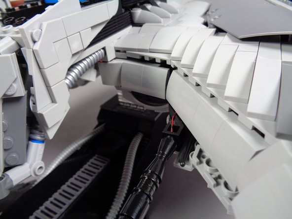
The third photo shows what your gun setup should look like once mounted and once the light wires have been hidden behind the armor sections.
-
-
-
As shown in the photos for this step, follow the same procedure to attach the second gun and run its light wire into the center of the head section.
-
-
-
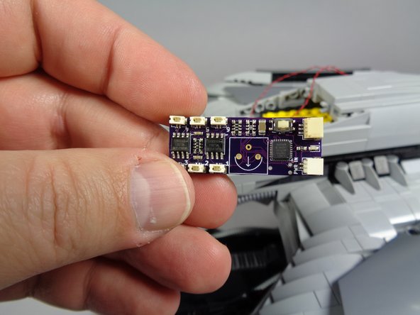
Next you will connect the two guns to the lighting effect controller included with your kit. Remove the controller from Bag 1. The controller is shown in the first photo for this step.
-
Next you will need to decide which firing configuration you would like for your guns. This kit supports two firing modes:
-
Mode 1: alternating fire mode. In this mode, each gun will fire on its own random interval.
-
Mode 2: synchronized fire mode. In this mode, both guns will always fire together.
-
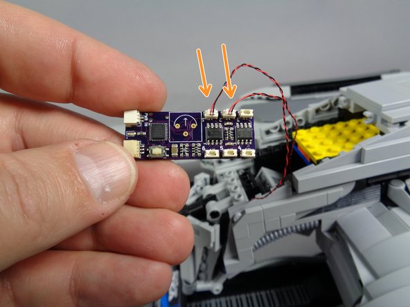
To set your guns up in Mode 1, follow the two orange arrows in the second photo and connect the guns to plugs #1 and #2 on the lighting effect controller. It does not matter which gun you connect to plug #1 and #2.
-
Be careful when connecting wires. The plugs will connect only one way-- do not force! Gently press the plugs into their sockets using your fingernail to connect-- you will feel a soft "click" when the plugs are fully inserted.
-
To set your guns up in Mode 2, follow the two purple arrows in the third photo and connect the guns to plugs #1 and #5 on the effect controller.
-
You can change the gun mode any time by moving the plugs.
-
-
-
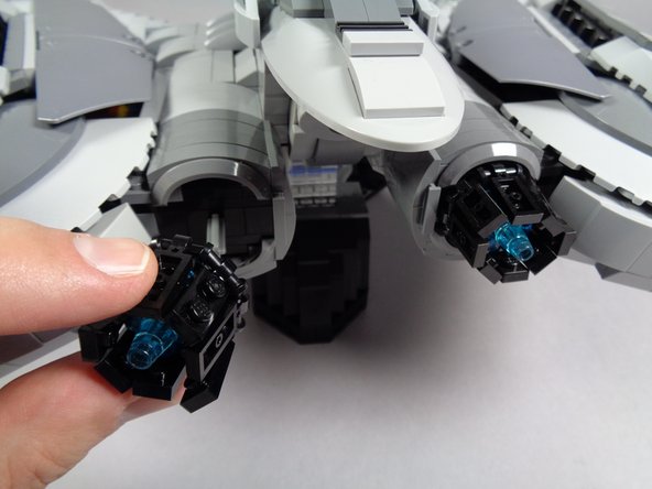
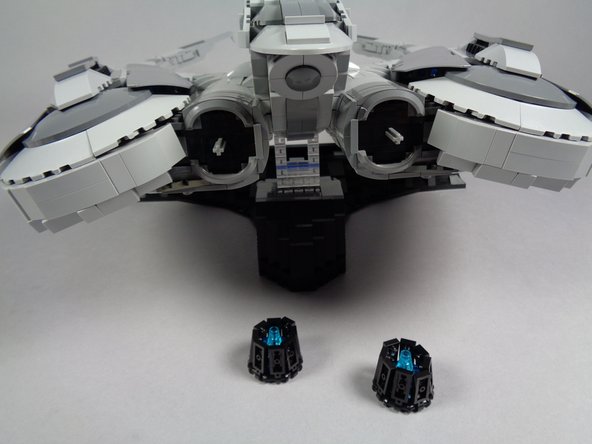
As shown in the first two photos for this step, carefully remove the two engine assemblies from the back of your Raider.
-
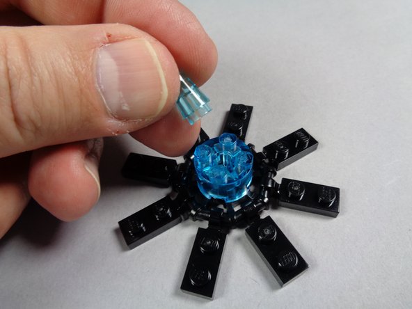
As shown in the third photo, open the plates around the engine core for both engine assemblies.
-
Also as shown in the third photo, remove the center transparent blue cone from the top of each engine.
-
-
-
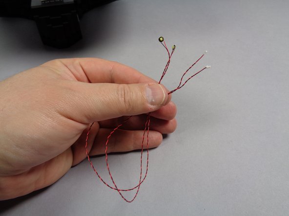
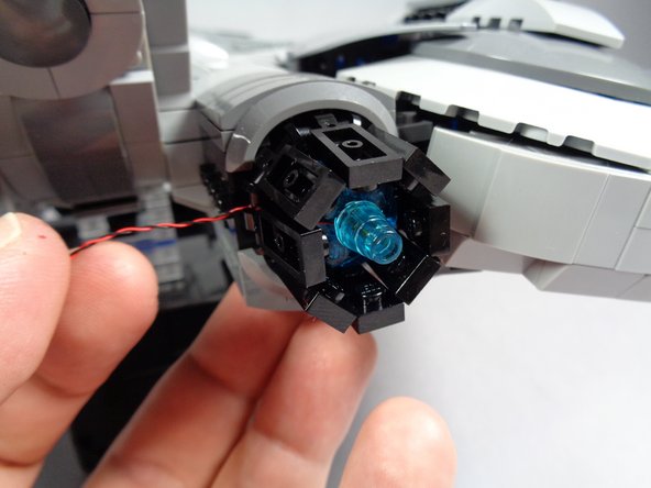
As shown in the first and second photos for this step, take the two cool white Pico LED lights from Bag 1, and place one Pico LED in the center of each engine.
-
As shown by the orange circle in the second photo, make sure the Pico LED light is facing upward.
-
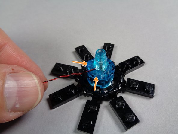
As shown in the third photo, carefully re-attach the transparent blue cone to the center of the engine, on top of the Pico LED light.
-
The two orange arrows in the third photo show how the light wire should pass: BETWEEN, not on top of, the studs of the larger brick below. Always make sure wires pass between, not on top of, studs.
-
-
-
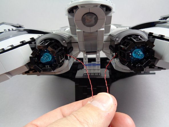
As shown by the yellow circle in the first photo for this step, pass the pug and wire for each light through the gap in the black base part.
-
The second photo shows how the light wire should pass out the back of the engine.
-
As shown in the third photo, close the circle of plates around the engine core.
-
Repeat this process for both engines.
-
-
-
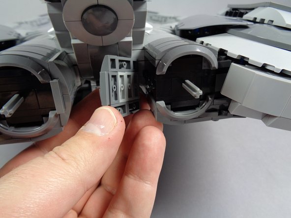
As shown by the first photo in this step, carefully remove the parts that form the inner engine shell. Do this for both the left and right engines.
-
As shown in the second photo, carefully re-attach both engines to their axles.
-
When re-attaching the engines, make sure the light wires for each pass on the inner side, toward the center of the Raider.
-
The third photo shows what your engines should look like after both have been re-attached.
-
-
-
Next you will feed both engine light wires into the main head area. This is perhaps the hardest installation step, so take your time. It may help to have a flashlight and tweezers handy to use in finding a path for the wires.
-
As shown in the first photo for this step, open the rear center panel of the Raider, and pass each light wire through the center, toward the front of the head.
-
There is a gap in the bricks, shown by the orange circle in the first photo. Pass each light wire through this opening, as shown by the green arrows.
-
Carefully feed each engine light wire through the inside of the head, toward the front. As shown by the blue rectangle in the second photo, you should be able to pull the ends of each light wire under the yellow plate so they pass into the front head section.
-
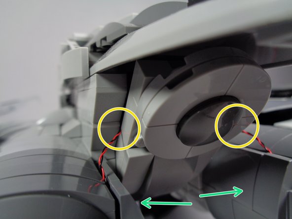
As shown by the green arrows in the third photo, re-attach the inner engine frames, making sure the light wires pass next to, and not on top of, any studs.
-
As shown by the two yellow circles in the third photo, carefully close the rear panel so it holds both light wires in place.
-
Make sure to leave a little extra wire for each engine outside the Raider before closing the rear panel. This will allow the panel to close without pulling and possibly breaking the wires.
-
-
-
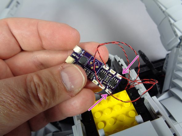
As shown by the two purple arrows in the photo for this step, connect the two engine light wires to plugs #3 and #4 on the effect controller.
-
It does not matter which engine you connect to each plug.
-
-
-
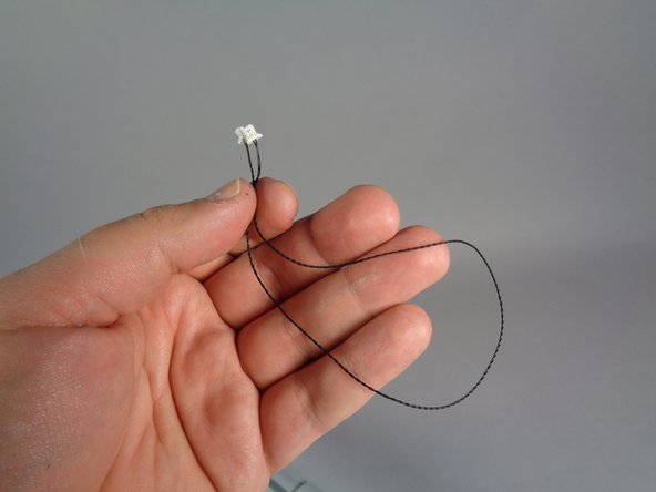
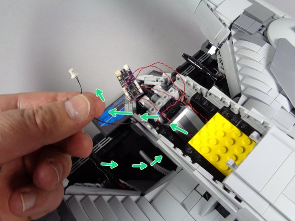
Next, take the black power wire from Bag 1 (shown in the first photo), and pass it through the bottom of the head and up through the inside of the head as shown by the green arrows.
-
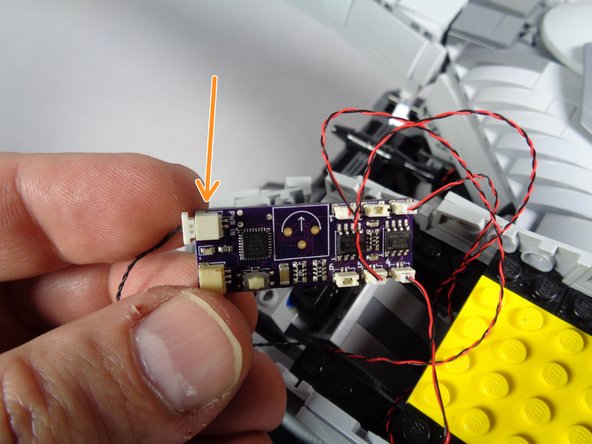
As shown by the orange arrow in the second photo, connect the power wire to the PWR IN plug on the effect controller. Make sure the power plug is pressed all the way into the socket.
-
Plugs will insert in only one direction-- do not force!
-
Make sure to connect the power wire to the PWR IN plug as shown, NOT to the larger plug next to the PWR IN plug.
-
-
-
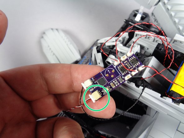
As shown by the green circle in the first photo for this step, connect the 3-wire plug that connects to the eye assembly to the other large plug on the effect controller.
-
Plugs will insert in only one direction-- do not force!
-
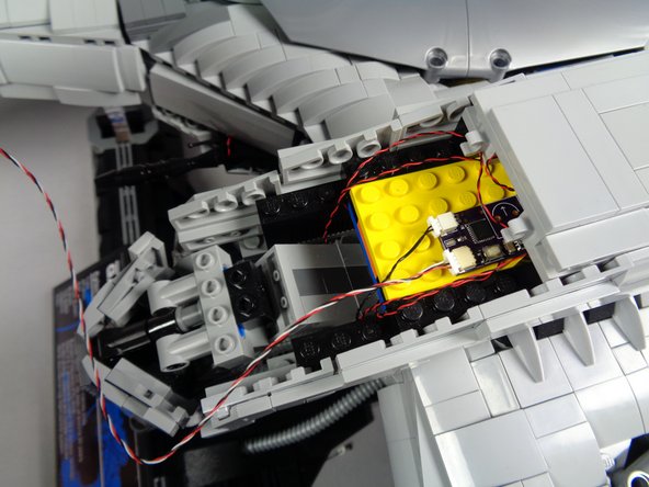
As shown in the second photo, place the effect controller and all connected wires inside the head-- there is open space to hold the controller and all wires. Make sure any excess wire is coiled up so it does not stick out of the head section.
-
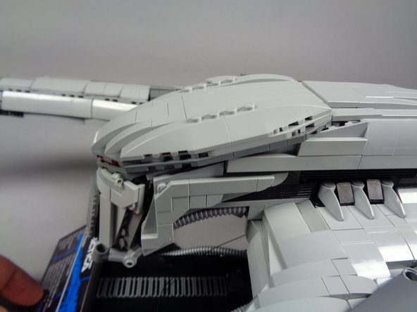
As shown in the third photo, re-attach the top of the head section, making sure not to pinch any wires in the clips that hold the top of the head to the body.
-
-
-
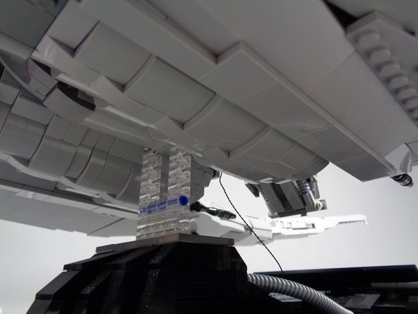
As shown in the first photo for this step, you should have the power wire coming out the bottom of the head.
-
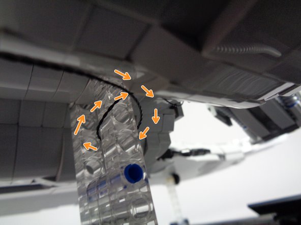
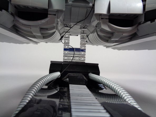
As shown by the orange arrows in the second photo, wrap the power wire several times around the clear base supports to provide tension relief.
-
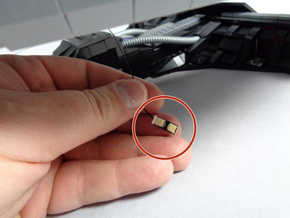
As shown in the third photo, take the small adapter from Bag 1 (labeled BRANCH13 on the back) and connect the power wire plug to one end of the adapter. It does not matter which end.
-
-
-
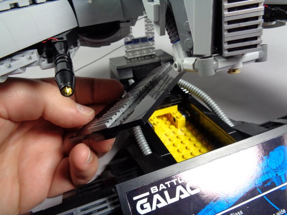
As shown by the orange arrow in the first photo, connect the plug from the battery pack wire to the other end of the BRANCH13 adapter.
-
Make sure you insert three fresh AA batteries into the battery pack.
-
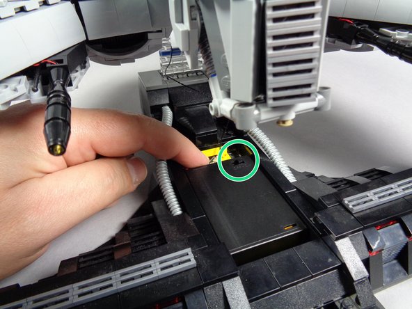
As shown in the second photo, remove the center plate from the support stand. There is a compartment inside designed to hold the battery pack.
-
As shown by the green circle in the third photo, place the battery pack inside the base with the power switch facing up (for each access).
-
-
-
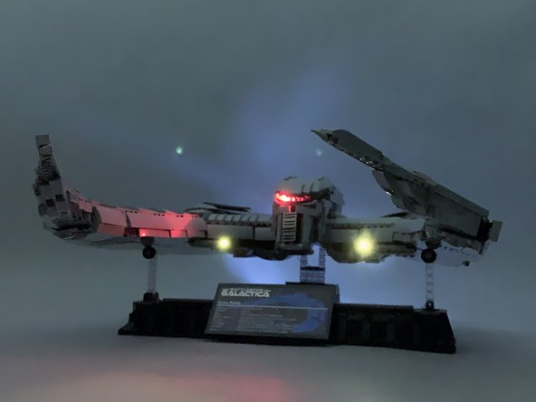
Once power is turned on, the lights in your Raider should turn on and begin their effects.
-
The eye will move back and forth.
-
The guns will pause and fire at random intervals according to how you connected them to the effect controller (either together or separately).
-
The engines should turn on.
-
There is a white button on the effect controller-- you can push this to switch the engines mode from "pulsing" to "steady" and back again. Your setting is preserved even when power is turned off.
-
If you would like to power your Raider from mains power, you can purchase our USB power cable (sold separately), connect this instead of the battery pack, and power your Raider from an iPhone or iPad-type charger with USB plug output.
-
-
-
Congratulations-- your setup is complete!
-
We hope you enjoy your Cylon Raider light kit as much as we enjoyed making it for you.
-
If you have any trouble or questions, you can always contact us at support(at)brickstuff.com.
-
Please share photos and video of your Raider in action, and use a #brickstuff hashtag so we can share your posts!
-


