
Tools
Parts
Featured Document
-
-
There are several ways to read this guide:
-
Reading it on the web in your browser.
-
Downloading a PDF copy of the guide. You can do this by selecting "Download PDF" as shown by the red rectangle in the first photo. Click on the Options heading in the upper right corner of the screen (see the green rectangle).
-
In the "Dozuki" application, which is available for download from the Apple App Store and various Android and Google marketplaces.
-
If you view this guide in the Dozuki app, search for "Brickstuff" the first time you open the app, then select "Product Guides" from the categories listed under Brickstuff. Scroll down to find this guide.
-
You can also translate this guide into another language when viewing on the web. To do this, install a translator extension into your browser and use that extension/plug-in to translate the page. Using the main Google translate website (translate.google.com) does not work.
-
-
-
As shown in the first photo, it is very important to look at the color of the wires for the lights in this kit.
-
Lights with red and black wires can be connected to any adapter their plugs will fit into.
-
Lights with blue and white wires can ONLY be connected to either a BRANCH09 or BRANCH09X adapter board. Connecting a light with blue and white wires to any other adapter board (including other adapters where the plugs fit) will destroy the light.
-
The second photo is a visual reference for the controllers and adapter boards included with your kit. You may want to print a copy to reference as you walk through the instructions. You can download a PDF copy of this illustration here.
-
Here are some other very important tips to keep in mind as you connect the parts in this kit:
-
Plugs connect to adapter boards and controllers only one way. Do not force plugs.
-
Do not remove plugs with tabs by pulling on the wire. Always use your fingernails or tweezers to remove plugs by pulling on the tabs of the plug, not the wires.
-
Many boards have connectors that face vertically (upward). Use extra care when connecting or disconnecting plugs to these connectors. Pulling or pushing sideways on any vertically-facing plug can cause the plug to come detached from its circuit board.
-
-
-
This kit includes a bag of spare parts. If you damage a wire or light while installing your kit, you can use one of the spares in the Spare Parts Bag.
-
Note that the Spare Parts Bag does not include replacements for all parts. If you damage a part that is not included in the Spare Parts Bag, contact us to purchase a replacement.
-
-
-
Before starting to install the lights, separate your Hogwarts castle into its two halves. You will install lights into the "Great Hall" half of the castle first.
-
At multiple points during the installation, you will be working with your castle set on its side, so you can access the large spaces beneath the rock elements. This is where the majority of wires will run in the first section.
-
As shown in the first photo, carefully remove the top section from the large tower. This will make it easier to rest the castle on its side in later steps.
-
As shown in the photo (red arrows), make sure the top part of the tower removes cleanly, with all dark tan parts still attached to the underside of the top section.
-
-
-
As shown in the photos for this step, carefully remove the top parts of the boathouse. This is where you will begin your installation.
-
-
-
Take the bag labeled "Dock Torches" from your kit box, and carefully remove the two replacement torch parts.
-
The wires on the dock torch lights are extremely thin, and they can easily become tangled. If this happens, carefully un-tangle the wires, being careful not to pull. Pulling can damage the lights.
-
Install the two replacement dock lights as shown in the second photo.
-
As shown in the third photo by the blue line, carefully run the thin wires next to the studs on the dark tan plate.
-
Whenever you are running wires, be very careful to run them along the side of studs, or between studs. Never run wires on top of or over studs-- doing so will cause the wires to become pinched or cut when you snap parts on top of the wires.
-
-
-
As shown in the photos for this step, carefully re-attach the boathouse parts, being careful to keep the wires along side of the studs when you snap parts on top of them.
-
As shown by the red arrows, the thin wires should extend out the back of the boathouse. Here again, make sure the wires run between the studs on the dark bluish gray plate in back when you snap the tan parts back on top of it.
-
At the end of this step, you should have a re-assembled boathouse as shown in the third photo.
-
-
-
This is the first of several times you will be laying your castle on its side.
-
Make sure you are working in a large enough space to allow the full castle to be laid on its side without any side or top parts hitting anything in your work area.
-
While tilting the castle backwards, you can hold the backside with your hand to help ease it onto your work surface. To minimize the chance of damage, move the castle slowly.
-
If anything breaks or any parts come loose, it is a good idea to keep the original LEGO® installation instructions nearby.
-
After you have tilted your castle on its side and rested it on your work surface, it should look like the example in the photo.
-
-
-
As shown in the photos for this step, carefully feed the boathouse wires through the holes in the Technic bricks at the base of the castle. The plugs are small enough that they will fit through the holes.
-
As shown in the second and third photo, wrap the wires several times around the light bluish gray brick close to the rear of the castle. This provides tension relief and helps keep the wires from scraping when you move your castle.
-
An important part of success in installing this light kit is making sure the wires that run underneath the castle are protected from scraping between the bottom of the castle and the surface you place it on after installing the light kit. If any wires scrape, they are more likely to break or cause a short circuit over time.
-
-
-
Note that, due to supply chain availability at the time your kit was manufactured, your kit may include 24" red 3-wire cables instead of 12" cables. If your kit has wires longer than 12", follow the instructions as usual but coil up any excess wire inside your Castle.
-
Remove the BRANCH09X adapter board from Bag 1, along with the two 3-wire connecting cables (the longer 12" cable will be red, but the shorter 1.5" cable may be black or red). Make sure to use 3-wire cables and not 2-wire cables. 2-Wire plugs will fit into 3-wire sockets but will not operate correctly.
-
As shown in the first photo, connect the RED 12" 3-wire connecting cable to the INPUT plug on the BRANCH09X adapter, and connect the short 1.5" 3-wire connecting cable (RED or BLACK) to the OUTPUT plug.
-
As shown in the second photo, connect the two boathouse light wires to outputs #1 and #2 on the BRANCH09X adapter board.
-
It is critical that you pay close attention to which output plug you connect each light. If the lights are not connected exactly as shown in this guide, they will not operate correctly.
-
As shown in the third photo, thread the red wire through the gap in the wall as shown by the green arrow. The cable should pass through the gap and out through the rear of the castle.
-
-
-
To prepare for installation of the four main hall torches, remove the torches that came with your LEGO® set as shown in the first photo.
-
As shown in the second and third photo, remove the brown benches and also the brown tile in front of the raised chairs (blue arrows in the third photo).
-
-
-
Remove Bag 5 from your Brickstuff kit. This bag contains four replacement torches with lights pre-mounted.
-
Carefully remove the four torches from the bag and make sure the wires are not tangled.
-
The light wires are very thin and easily tangled. If you need to un-tangle any wires, do so carefully, making sure not to pull on the wires. Pulling on the wires could cause the lights to come detached from the torches.
-
Note that the wires connecting to the torches may be different colors than the wires shown in the photos here. your wires may also be thicker. That is ok.
-
As shown in the third photo, carefully route the wire for the first torch down the wall and next to (not on top of) the stud closest to the wall as shown by the red circle in the third photo.
-
Make sure to leave a little extra wire along the wall running up to the torch. When you snap the LEGO® parts back on top of the wires, they will pull down a bit. Without a little slack, there is a chance the lights will be pulled from the torch when you re-attach parts in later steps.
-
-
-
As shown in the first photo, re-attach the LEGO® plate on top of the first torch light wire.
-
As shown in the second photo, run the wire from the first torch near the second torch, then run the wires from the first three torches toward the outer edge of the hall as shown by the red arrows in the second photo.
-
As shown in the third photo, carefully re-attach one of the brown benches on top of the wires for the first three torches.
-
-
-
As shown in the first photo, run the wire from the fourth torch down the wall as you did for the first three torches.
-
Remember to leave a little extra slack in the wire along the wall so the light won't be pulled from the torch when you re-attach the benches.
-
As shown in the second photo, re-attach the second brown bench and gather all four light wires along the left side of the row of benches as shown by the red arrows.
-
As shown in the third photo, carefully re-attach the second row of benches.
-
When re-attaching the brown benches, make sure the light wires run between, not on top of, the brown studs on the floor.
-
-
-
As shown in the first photo, carefully re-attach the third row of brown benches.
-
As shown in the second photo, gather the wires to the left of the last row of benches.
-
Carefully re-attach the last row of benches. When you are done, the wires should run as shown in the third photo.
-
-
-
The four wires from your torches should now look like the torches in the first photo.
-
As shown by the green arrow in the second photo, feed the four torch light wires into the gap in the wall below the main hall.
-
If you carefully lift the castle, you should see the four torch wires extending out the bottom as shown by the green circle in the third photo.
-
-
-
As shown by the red circle in the first photo, feed the four torch light wires through one of the holes in the light bluish gray brick at the base of the castle.
-
As shown in the second photo, wind the four torch light wires several times through the holes in the Technic brick so there is little slack left.
-
Remember, it is important that wires do not scrape between the bottom base and the surface you will mount your castle on. If wires scrape between the castle base and the surface below, wires will become damaged over time.
-
As shown by the four red arrows in the third photo, connect the four hall torches to plugs #3,4,5, and 6 on the BRANCH09X adapter board.
-
It does not matter which order the four torch wires are connected to the BRANCH09X adapter board, as long as they are connected to plugs 3,4,5, and 6.
-
-
-
Remove the "Green LEDs Bag" from Bag 1, and remove one of the green lights from the bag.
-
Keep the other green light inside the "Green LEDs Bag" so you don't confuse it with the other lights. You will use the second green light in a later step.
-
As shown in the second and third photos, use one of the small sticky squares in Bag 1 to attach the green light to the area in the Chamber of Secrets above the snake.
-
-
-
Remove the two cool white lights from Bag 1 and use two small sticky squares to attach them to the left and right sides of the green light as shown in the second photo.
-
The green arrow in the second photo shows the position of the green light, and the two blue arrows show the position of the two cool white lights.
-
As shown in the third photo, tie the ends of the wires for the two cool white lights together. This will help identify them when you connect them in the next step.
-
-
-
As shown by the red arrows in the first photo, feed the wires for the three lights in the Chamber of Secrets into the opening at the left.
-
As shown by the red circles in the second and third photos, use one of the large sticky squares from Bag 1 to hold the three light wires to the top of the open space under the castle.
-
-
-
As shown by the green arrow in the first photo, connect the wire for the green light to plug #9 on the BRANC09X adapter board.
-
As shown by the two blue arrows in the second photo, connect the wires for the two cool white lights to plugs #7 and #8 on the BRANCH09X adapter board.
-
You can tell the wires for the two cool white lights because you tied them together in the previous step.
-
Make sure no light wires scrape between the bottom castle base and the surface you mount the castle on. If there is any slack in wires, coil them around the Technic bricks inside the castle base so no wires hang down to scrape.
-
-
-
Remove the master controller board from Bag 1. The controller, labeled TRUNK08 on the bottom side, is shown in the first photo.
-
The controller included with your kit may have fewer connecting plugs installed than the one shown in the photo. This will not affect the operation of your set.
-
As shown in the second photo, you should have one red 3-wire connecting cable extending out the back of the castle.
-
As shown by the red circle in the third photo, connect the red cable to the plug labeled "PIXEL" on the TRUNK08 main control board.
-
-
-
Bag 2 in your kit contains one 4-button remote control and a pre-wired remote receiver module.
-
As shown by the two red arrows in the second photo, connect the power cable from the remote receiver (2-wire red/black wire) and the 4-wire remote control cable to the plugs on the TRUNK08 main control board as shown.
-
Take the USB power cable from your kit and connect the power wire to the TRUNK08 main control board as shown by the green arrow in the third photo.
-
-
-
Connect the USB cable to a power source. The green power light on the TRUNK08 main control board should turn on.
-
If the green power light not come on, double-check to make sure all plugs are fully inserted.
-
Once connected to power, the lights you have connected so far should turn on and begin running their effects automatically. The video in this step shows how the effects should look.
-
If the effects are different from those shown in the video, you may have connected lights to the BRANCH09X adapter board in the wrong order. Go back and check the lighting connections and compare to earlier steps in this guide to make sure the lights are connected to the correct plugs on the BRANCH09X adapter board.
-
If your lights do not look and operate as shown in the video, do not continue installation. Double-check all connections, and if lights still do not work, contact us at support@brickstuff.com for further assistance.
-
-
-
Remove Bag 7 from your kit. Bag 7 will contain the parts needed to mount the lights inside the eight windows of the main tower, and also parts needed to start mounting lights in the top of the tower.
-
Carefully remove the parts from Bag 7, making sure not to tangle any wires (or to carefully un-tangle any wires that may have become tangled).
-
The second photo shows the parts from Bag 7 that you will use first.
-
As shown in the third photo, carefully remove the side panels from the main tower.
-
-
-
Your kit includes eight warm white lights pre-mounted inside tan 1x2 LEGO® jumper plates. You can choose to mount these lights randomly in windows in any of the tower panels.
-
To mount each light, use a LEGO® brick separator to remove the parts surrounding the already-installed windows in your castle.
-
Next, as shown in the second photo, make sure each pre-mounted light is flat against the top of the jumper stud.
-
Remove the transparent dark clear plate from the window in your LEGO® set and carefully attach it on top of the stud with the pre-mounted light as shown in the third photo.
-
For best results, do not install lights in the top row of windows in any tower section. Installing lights too high up may make their wires too short to reach to the connecting point in future steps.
-
If you later find a wire is too short to reach its adapter board, you can remove the tower section with the high window and re-mount it one or two levels lower.
-
-
-
As shown in the first photo, carefully re-attach the pre-lit window by running the wire to one side and to the top of the light, then re-attaching to the main tower structure.
-
When re-attaching the window, make sure the light wire runs next to and not on top of studs.
-
Re-attach the tower pieces that surround the window, so it looks just like it did before you took it apart.
-
Repeat this process for each tower window you want to replace with a pre-lit window.
-
After mounting the eight windows, you will have tower panels like the one shown in the third photo, with wires extending to one side and all other pieces re-attached.
-
-
-
There should be three warm white Pico LEDs with 12" cables and three transparent LEGO "boat stud" parts inside Bag 7. You will use these to mount lights on the ceiling of each of the three staircase sections as shown in the first photo.
-
Use the "boat stud" parts to hold the Pico LEDs in place as shown in the first photo. When attaching the LEDs, make sure they face downward.
-
As shown in the second photo, pull the LED wires out through the back of the staircase section.
-
As shown in the third photo, make sure the wires for the three staircase lights run up the tower toward the top. This will be the opposite of the eight window lights, whose wires will run down into the base of the castle.
-
-
-
Remove one of the BRANCH09X adapter boards from Bag 7, and as shown in the first photo, connect one of the 24" three-wire connecting cables (RED OR BLACK) in Bag 7 to the INPUT connector on the BRANCH09X adapter.
-
Note that the 3-wire connecting cables shown in this guide are black, but the wires included with your kit may be red instead. The cables work identically.
-
As shown in the second photo, thread the wires for the three staircase lights under the round brick at the top of the tower. This will hold the wires in place.
-
As shown by the arrows in the third photo, connect the three stairway lights to plugs #1, #2, and #3 on the BRANCH09X adapter board.
-
-
-
As shown in the first photo, carefully remove the long side panel of the castle tower. Make sure the entire panel comes off, all the way down to the pink plate as shown.
-
With the side panel removed, the tower will be more fragile than normal. Be careful not to tip your castle when the panel is removed, or the tower could fall over.
-
As shown in the second photo, you should have your BRANCH09X adapter board with the three staircase lights connected to plugs #1, #2, and #3, and with the 24" 3-wire connecting cable plugged into the INPUT plug (green arrow).
-
Make sure your 24" 3-wire connecting cable is plugged into the INPUT plug on the BRANCH09X adapter as shown by the green arrow, not the OUTPUT plug as shown by the red 'X'.
-
As shown in the third photo, carefully run the 3-wire connecting cable down the side of the tower and down through the hole at the base of the tower, as shown by the green arrow.
-
Thread the cable down through this hole so it feeds down to the underside of the castle base. You may need to feel around with the wire several times before it will feed cleanly through into the base.
-
The 3-wire cable should be fully fed into the castle base with just enough slack to reach the BRANCH09X adapter board at the top of the tower.
-
-
-
Remove the second 24" 3-wire connecting cable (this may be BLACK or RED) from Bag 7, and connect it to the OUTPUT plug on the BRANCH09X adapter board as shown in the first photo (green arrow).
-
As shown in the second photo, make sure all wires from the top of the tower feed through the space under the round tan brick as shown by the blue circles. This will hold the cables in place.
-
If needed, you can remove the round tan brick at the top of the tower in order to feed the cables through the space underneath.
-
When feeding cables, make sure they all run through the space under the brick, not between the brick and any studs below. This could pinch the wire.
-
Run the 3-wire connecting cable down the side of the tower so it sits near the base as shown in the third photo.
-
Unlike the INPUT cable (blue arrow in the third photo), this OUTPUT cable (green arrow) will not feed under the castle base but will instead hang loose.
-
-
-
As shown in the first photo carefully re-attach the long tower panel.
-
Make sure none of the wires covered by the long tower panel are pinched between any studs. This is especially critical at the tower base, where there is a large side-facing plate. If wires get pinched, they can break.
-
Once you have completely re-attached the tower side panel, you should have the 3-wire OUTPUT connecting cable extending outside of the castle as shown in the second photo.
-
Remember, the 3-wire connecting cables shown in this guide are black, but the wires included with your kit may be red instead. The cables work identically.
-
-
-
Next you will run the wires from the eight window lights DOWN into the space beneath the castle.
-
Carefully re-attach the panels you removed in Step 22, beginning with the two narrow panels.
-
When re-attaching each panel, be careful that wires do not become pinched by any studs behind the panels. Route the wires to the side of each panel and make sure no wires are pinched between studs.
-
As shown by the green circle in the second photo, carefully feed each light wire through the hole at the base of the tower. Push the wire all the way into the hole so there is as little slack above the ground level as possible.
-
Lights that are mounted toward the top of a tower section may just barely reach the connection point underneath the castle. For this reason, make sure wires have as little slack as possible after feeding through the hole shown in the second photo.
-
Repeat this process for the two narrow side panels, and do the center (larger) panel last.
-
The center panel will be more difficult to attach than the others. As shown in the third photo, feed the wires down into the hole in the base of the castle, then carefully re-attach the last panel.
-
After re-attaching the last panel, check around the tower to make sure no wires are showing.
-
-
-
Carefully turn your castle on its side and lay it on a soft, flat surface.
-
As shown in the first photo, gather the eight wires from the window lights that you fed down from the tower in the previous step.
-
It may be difficult to locate all eight wires. When you fed the wires down into the castle base in the previous step, some wires may have gotten stuck. If you can't locate all eight wires, use a flashlight and tweezers to search up inside the base of the castle until you have located all eight wires.
-
If any wires are too short to reach, you will need to check back under the window panels above to see if there was excess slack in any of the wires. If all wires are pulled tight but still do not reach, you may need to re-locate the window light for any short wires one or two levels lower in the tower panel (refer to Steps 26-27).
-
Take the second BRANCH09X adapter board from Bag 7 and connect the eight window light wires to plugs #2 through #9 on the adapter board.
-
Do not connect any window lights to plug #1 on the BRANCH09X adapter. You will use this plug for another light later. If you connect a window light to plug #1, the effects will not work properly.
-
-
-
After you have connected all eight window lights to the BRANCH09X adapter board in the previous step, take the 24" 3-black (or red) connecting cable you fed down into the castle base in Step 30 and connect it to the OUTPUT plug of the BRANCH09X adapter board, as shown by the green arrow in the first photo.
-
Make sure you are connecting the 3-wire cable you fed down into the base in Step 27, NOT the cable you left hanging outside the castle in Step 32.
-
Make sure you connect the 3-wire cable to the OUTPUT plug on the BRANCH09X adapter board, NOT the INPUT plug.
-
Next, locate the first BRANCH09X adapter board you connected in Step 10. This is the adapter board with the short 1.5" 3-wire red or black cable connected to the OUTPUT plug. (see the board in the second photo)
-
Connect the other end of the short 3-wire red or black connecting cable to the INPUT plug of the BRANCH09X adapter board that has the eight window lights connected to it.
-
After connecting the two BRANCH09X adapter boards, your setup should look like the connections in the third photo.
-
The first BRANCH09X adapter board (with the blue wires connected to it) should have a 12" RED cable connected to the INPUT plug and the short 1.5" red or black cable connected to the OUTPUT plug.
-
The second BRANCH09X adapter should have the other end of the short 1.5" red or black cable connected to its INPUT plug, and should have the 24" black cable from the top of the tower connected to its OUTPUT plug.
-
-
-
Take the second green LED from Bag 1 (inside the smaller bag labeled "Green LEDs") and attach a small sticky square to the back as shown in the first photo.
-
Feed the LED wire through the small gap in the base of the tower as shown by the blue arrow in the second photo.
-
As shown by the red circle in the third photo, mount the green LED to the BACK side of the plate above the door at the base of the tower.
-
-
-
As shown by the green arrows in the first photo, connect the green LED to plug #1 (the last available plug) on the BRANCH09X adapter board with the window lights connected to it.
-
Using two sticky squares from Bag 1, carefully mount the first BRANCH09X adapter board inside the base of the castle as shown in the second photo.
-
As shown in the third photo, tuck all remaining wires along with the second BRANCH09X adapter board up into the same space as the first BRNACH09X adapter board.
-
Make sure that no wires are hanging below the base of the castle. Any wires left hanging will rub against the LEGO base plates and the surface you use to display your castle, causing the wires to break over time.
-
-
-
If your kit includes a sound module, you can complete the next few steps to install the speaker. If your kit does not include a sound module, you can skip ahead to the next main section.
-
Take the speaker and carefully remove it from its cardboard box.
-
Inside Bag 7, there should be two squares of double-stick tape (see the second photo). You will use these to mount the speaker inside the base of the castle.
-
Note that the tape squares included with your kit may look different than the ones shown in the photo. That is ok.
-
As shown in the third photo, stick one of the double-stick tape squares to the back of the speaker in preparation for mounting. (You can save the extra square in case you need to move or re-mount the speaker in the future)
-
-
-
As shown in the first two photos, carefully insert the speaker facing upward into the space beneath the castle. Gently press the speaker down so it sticks firmly to the two dark bluish gray plates as shown in the second photo.
-
As shown by the red arrows in the third photo, carefully feed the speaker cable around and through the base of the castle, so the speaker cable passes through the same gap in the castle base as the 3-wire red connecting cable you ran in Step 7.
-
The plug for the speaker should hang out the back side of the castle.
-
Make sure the speaker wire does not pass under the bottom of the castle base, where it will rub against the surface you place your castle on.
-
-
-
If your kit includes color-changing spotlights, now is a good time to mount the first five of them since your castle is already on its side with the bottom exposed. There should be a total of 10 spotlights in Bag 11 in your kit.
-
Inside Bag 11, there should be a special cable approximately 36" in length. As shown in the first photo, this cable has a small connector on one end (red arrow) and a larger connector on the other end (blue arrow). Both connectors have three wires.
-
Bag 11 should also contain two BRANCH17 adapter boards. These have large plugs on either end and five smaller plugs in the middle of the board. As shown by the blue arrow in the second photo, connect the end of the cable with the larger plug to the end connector on the BRANCH17 adapter board labeled "IN".
-
Note that the BRANCH17 adapter boards included with your kit may have side-facing connectors instead of the top-facing connectors shown in the photos here. That is ok-- both designs of the board work identically.
-
-
-
Take five of the color-changing spotlights from Bag 11 and connect them to the five plugs labeled "RGB1" through "RGB5" on the BRANCH17 adapter board as shown by the orange arrows in the first photo.
-
You should also have one 24" black or red 3-wire connecting cable in Bag 11. As shown in the second photo, connect one end to the plug labeled "OUT" on the BRANCH17 adapter board.
-
As shown in the third photo, take two sticky squares from Bag 11 and attach them to the backside of the BRANCH17 adapter board.
-
-
-
Now that you have the five spotlights connected to the BRANCH17 adapter board, use the sticky squares to mount the adapter along the long white brick under the castle, next to the speaker as shown in the first photo.
-
As shown in the second photo, take the small connector from the wire connected to the "IN" plug on the BRANCH17 adapter board and the large connector on the wire connected to the "OUT" plug, and run both wires under the castle and out the back as shown in the third photo.
-
The blue arrows in the third photo show the path the two wires should take, under the castle and out the back.
-
-
-
Now you can attach the five spotlights to the castle base. It's up to you where to mount them-- in general the lights should be evenly spaced along the front and side edge of the castle base, shining up on the castle.
-
When you run the spotlight wires, make sure they do not run under any plates-- see the red "X" in the first photo for an example of how not to run the wires. The wires should run above any plates as shown in the second photo so they do not rub against the base when the castle is upright.
-
-
-
When attaching each spotlight around the castle base, make sure to run the wires on top of the bottom plates so no wires run under plates and rub against the base when the castle is upright.
-
The three photos in this step show various ways to mount the spotlights.
-
Where you position the spotlights is up to you. You can adjust the spotlights up or down as needed after they have been mounted-- just make sure to leave enough extra wire close to the spotlight to allow it to move up and down.
-
-
-
Carefully re-position your castle so it again sits upright.
-
There should be two main wires extending through the gap in the center of the castle:
-
Red 3-wire connecting cable, as shown by the red circle and arrow in the first photo.
-
Black speaker cable, as shown by the blue circle and arrow in the first photo.
-
Note that the red wire shown in the second photo should still be connected to the BRANCH08 master controller after you tested the first section of lights in Step 21.
-
As shown in the second photo, you should still have the three wires connected to the TRUNK08 master controller (USB power, remote control receiver power, and remote control receiver output).
-
If your kit includes color-changing spotlights, you will also have two extra wires extending through the gap in the center of the castle: the 3-wire cable with the large connector and the red/white/black cable with small connector. These are the wires from the BRANCH17 adapter board for the color-changing spotlights.
-
As shown in the third photo, take the spotlight wire with the small connector and insert it into the plug labeled "SENS1" on the TRUNK08 main controller.
-
-
-
Make sure the TRUNK08 master controller is connected to power, and the lights should operate as shown in this video clip.
-
If the staircase lights are not on, you can try pressing and holding the "B" button on the remote control for 2-3 seconds, then releasing. This "long press" on button "B" should turn the interior lights on.
-
All lights from the first test you completed in Step 24 should also continue to operate correctly when you perform this second test.
-
Make sure all eight window lights turn on and off at random intervals. It make take up to 90 seconds for all lights to come on, so be patient and make sure all eight lights are cycling on and off.
-
If your lights do not look and operate as shown in the video, do not continue installation. Double-check all connections, and if lights still do not work, contact us at support@brickstuff.com for further assistance.
-
-
-
Next, you will install the pre-wired lamp post string. As shown in the first photo, remove the 9 lamp posts from your Hogwarts Castle.
-
The replacement pre-wired lamp post string is contained in Bag 4 (second photo).
-
As shown in the third photo, carefully unpack the lamp post string and lay it flat, making sure there are no tangles in the wires.
-
Never pull on any of the lamp post string wires. Doing so can cause a wire to become disconnected from one or more lamp posts. This cannot be repaired.
-
-
-
As shown in the three photos for this step, carefully mount the pre-wired lamp post string. It is ok to press down on the wires as you mount the lamp posts.
-
Lamp posts should sit straight up after being mounted.
-
As shown in the second photo, all wires should exit toward the rear of each lamp post. Wires should not be visible from the front.
-
You can use a tweezers to gently coil up any excess wire so it sits below the railing behind each lamp post. Just do not pull on the wires.
-
The third photo shows what your lamp post string should look like after mounting. The power wire should hang over the railing at the rear of the castle.
-
-
-
As shown by the green arrow in the first photo, connect the connector from the lamp post string to the plug labeled "OUT1" on the TRUNK08 master controller.
-
Connect the power to the TRUNK08 master controller, and the lamp post string should turn on.
-
As shown in the third photo, if the lamp post string does not come on when power is connected, you can press and release the "A" button on the remote control quickly (less than 1 second). This should turn the lamp post string on (a "short press" of the "A" button turns the lamp post string on and off).
-
If the lamp post string does not light up, double-check to make sure power is connected to both the TRUNK08 controller and also the remote control receiver, and that the lamp post string connector is fully inserted into the OUT1 plug on the TRUNK08 controller.
-
If your lamp post string lights but one or more individual lights do not light up, your string has become damaged during installation. Contact us to purchase a replacement.
-
-
-
Open Bag 3, which should contain three light strips, two short connecting cables, and one longer black connecting cable.
-
Note that the color of the connecting cable wires may be different than the wire shown in the photo-- you may have black wires or red/black wires. Also, your wires may be thicker than the wires shown in the photo. That is ok.
-
As shown in the second photo, connect the light strips end-to-end so a string is created with the longer cable on one end of the string.
-
As shown in the third photo, test-fit the three light strips in the courtyard.
-
Do not remove the adhesive backing of the light strips yet.
-
-
-
Begin mounting the light strips with the center strip. Remove the adhesive strip from the back of the center light strip and carefully press it under the dark bluish gray courtyard roof tiles so the light strip sticks to the underside of the center part of the courtyard roof (see the blue arrow).
-
Mount the other two light strips on either side of the center strip.
-
As shown in the second photo, remove the roof tile on the end of the courtyard, and feed the long black connecting cable through the window under the roof (see the red arrow).
-
As shown in the third photo, pull the longer cable all the way through the window so it comes out the rear of the courtyard.
-
Remember, the color of the wires may be different than the wires shown in the photos-- you may have black wires or red/black wires. Also, your wires may be thicker than the wires shown in the photos. That is ok.
-
-
-
As shown by the green arrow in the first photo, feed the light strip wire along the rear courtyard wall and through the gap between the tower and the main castle.
-
When feeding the cable, take care to make sure it does not become pinched between the castle and the tower. There should be room for the wire to pass without getting pinched.
-
As shown by the green arrow in the second photo, connect the light strip power cable to the plug on the TRUNK08 master controller labeled "OUT2".
-
Connect the TRUNK08 board to power. The courtyard lights should turn on. If they do not turn on, you can press and hold the "A" button on the remote control for 2-3 seconds, then release. A "long press" of the "A" button turns the courtyard lights on and off.
-
-
-
Open Bag 6. Inside there should be four lights: three with 6" connecting cables and one with 3" connecting cables (see the second photo for comparison of wire lengths).
-
Using the two transparent "boat stud" parts included in Bag 6, attach one light with 6" cable and one light with 3" cable to the ceiling in the main hall as shown in the third photo.
-
The green arrow shows the light with the 6" cable and the blue arrow shows the light with the 3" cable.
-
When mounting the lights under the "boat stud" parts, make sure they face downward.
-
-
-
Using a LEGO brick separator, carefully separate the roof section from the brown roof braces. This will allow you to run the light wires between the roof and the roof braces.
-
The second photo shows the results after the light wires have been secured between the roof and roof braces.
-
Make sure the light wires do not run on top of any studs when re-attaching the roof to the braces. All wires should always run next to or between studs.
-
As shown in the third photo, connect the two ceiling lights to any two of the four small connectors on the BRANCH15 adapter board included in Bag 6.
-
It does not matter which two small plugs on the BRANCH15 adapter you connect the lights to.
-
Take two small sticky squares from Bag 6 and stick them to the back of the BRANCH15 adapter board. You will use these in a later step to mount the BRANCH15 board to the wall.
-
-
-
Next you will disassemble a large portion of the courtyard clock tower so you can mount the remaining two lights with 6" cables. Follow the disassembly steps in the photos.
-
Although this looks like major disassembly, the sections of the clock tower can be removed while keeping large sections intact. Follow the steps in the photos, and it's always a good idea to have your original LEGO instruction book handy in case you forget where a piece goes during re-assembly.
-
-
-
Continue with the disassembly steps as shown in these photos.
-
As shown in the third photo, use a LEGO brick separator to remove the bottom 1x2 tan plate from the center arch assembly.
-
-
-
As shown in the first photo, take the 2x2 tan replacement plate from Bag 6 (blue arrow in the photo) and snap the remaining arch assembly parts (red arrow in the photo) on top. The result should look like the second photo.
-
Attach one of the two remaining lights with 6" cable to the bottom of the 2x2 tan plate using a sticky square as shown in the third photo.
-
As shown by the red arrow in the third photo, attach the light to the side OPPOSITE the sloped arch assembly.
-
-
-
Carefully re-attach the arch top as shown in the photo. The light should be facing the inside of the arch.
-
-
-
As shown in the first photo, remove the clock and its mounting bracket.
-
Remove the clock face from its bracket.
-
As shown in the second photo, insert the last light with 6" cable in the center of the assembly.
-
The second photo shows the light mounted beneath the dark bluish gray round plates, but you may get better light distribution by placing the light in the center on top of the plates, then carefully re-attaching the clock face directly on top of the light.
-
Re-attach the clock face. As shown in the third photo, the light wire should extend out the center top of the clock assembly.
-
-
-
Just a little more disassembly, we promise!
-
After removing the parts shown in the three photos, you should expose a gap as shown by the red arrow in the third photo. This is where you will run the light wires in the next step.
-
-
-
As shown in the first photo, take the wire from the arch assembly, feed it through the gap as shown, and re-attach the dark bluish gray slope piece to hold the wire in place.
-
The blue arrows in the second photo show how the wire should run.
-
Make sure the wire runs between the studs under the roof slope piece, and not over the tops of any studs. This can cause the wire to become pinched.
-
Re-attach the clock bracket as shown in the third photo, and feed its light wire through the same gap as the first wire.
-
-
-
Follow the steps as shown in the photos to re-assemble the clock tower.
-
When running wires between any parts, make sure the wires pass between, not on top of, any studs.
-
-
-
Continue with re-assembly as shown.
-
-
-
Complete re-assembling the clock tower as shown.
-
The third photo shows how the wire from the arch light should run.
-
-
-
As shown in the first photo, you should now have two wires extending into the main hall.
-
Connect the two wires to the two remaining small plugs on the BRANCH15 adapter board as shown in the second photo.
-
As shown in the third photo, take the 12" connecting cable from Bag 6 and connect it to one of the large plugs on the BRANCH15 adapter board.
-
It does not matter which large plug on the BRANCH15 adapter you connect the connecting cable to.
-
Remember, the color of the wires may be different than the wires shown in the photos-- you may have black wires or red/black wires. Also, your wires may be thicker than the wires shown in the photos. That is ok.
-
-
-
As shown in the first photo, use the sticky squares you attached in Step 54 to mount the BRANCH15 adapter board along the wall in the top corner of the main hall.
-
Coil up any loose wires so they are not hanging down.
-
using a LEGO brick separator, carefully separate the side roof section from the tan braces as shown in the second photo.
-
Run the connecting cable between the roof piece and the tan brace pieces, being careful not to pinch the wires over the top of any studs.
-
-
-
As shown by the green arrow in the first photo, connect the cable from the main hall lights to the plug labeled "OUT3" on the TRUNK08 master controller.
-
Test the lights by connecting power to the TRUNK08 board. The main hall ceiling lights and clock tower lights should turn on.
-
If these lights do not turn on, try pressing the "B" button on the remote control for less than 1 second as shown in the second photo. This is a "short press" on button "B" and it turns the main hall/clock tower lights on and off.
-
As shown in the third photo, check to make sure both clock tower lights are operational as well.
-
-
-
Open Bag 8, and remove three of the lights with 12" cables (see the first photo).
-
As shown in the second and third photos, remove the top of the tower and the section with the three smaller towers attached.
-
-
-
Remove the tops of the three smaller towers as shown in the first photo. Feed the wire from each light down through the center of the tower tops as shown in the second photo.
-
When you have fed the wire through each tower top, the light should look similar to the light shown in the third photo.
-
-
-
There should be three transparent red round 1x1 LEGO plates in Bag 8. Place one on top of each small tower roof, on top of each light as shown in the first and second photos.
-
Next, re-attach the topmost small tower as shown in the third photo.
-
-
-
As shown in the first photo by the green arrow, make sure the light wire runs down along the side of the topmost tower with a little extra slack. Also make sure the wires pass BETWEEN the studs on the round piece below.
-
Continue by attaching the other two towers, each time making sure the light wires run between and not on top of studs.
-
After re-installing all three small towers, your setup should look like the assembly in the third photo.
-
-
-
As shown in photo, remove pieces from the bottom of the top tower section.
-
-
-
Re-attach the three small rooftop towers.
-
As shown in the first photo, remove the roof section under the three small towers.
-
As shown by the green arrow in the second photo, wrap the three light wires from the small towers around the base.
-
Tie the three rooftop tower light wires together as shown in the third photo. This will make it easier to connect the rooftop lights later.
-
-
-
As shown by the blue circle in the photo, feed the three rooftop light wires down through the gap in the floor next to Dumbledore's office.
-
-
-
As shown in the first photo, take the third light and clear "boat stud" part from Bag 8 and mount the light on the ceiling of Dumbledore's office.
-
As shown in the second and third photos, route the light wire through the same gap in the floor as the three rooftop tower lights.
-
-
-
Inside Bag 8, there is a small bag with two wall torches inside. Carefully remove the torches and un-tangle their wires if needed.
-
Remove the existing wall torches and tan wall bricks from below the front of Dumbledore's office.
-
As shown in the second and third photos, mount the pre-lit wall torches and re-attach the wall section parts you removed earlier.
-
-
-
As shown in the first photo, re-attach the side roof section you removed earlier.
-
As shown in the second photo, bring the tower top section close to the lower section. You will need to keep the two sections close together while you connect the light wires.
-
As shown by the two orange arrows in the third photo, connect the two blue and white wires (from the wall torches) to plugs #4 and #5 on the BRANCH09X adapter board. This is the same board you connected the three stairway lights to earlier.
-
-
-
As shown by the red arrow in the first photo, connect the light from Dumbledore's office to plug #6 on the BRANCH09X adapter board.
-
As shown by the three orange arrows in the second photo, connect the three rooftop tower lights to plugs #7, #8, and #9 on the BRANCH09X adapter board. These wires should be tied together in a knot, making them easy to identify.
-
After all 9 plugs are used up on the BRANCH09X adapter board, tuck the board and all of the light wires into the space beneath Dumbledore's office, as shown in the third photo.
-
-
-
As shown by the red circle in the first photo, re-attach the tan half-circle piece below Dumbledore's office.
-
There should be two dark tan 1x2 LEGO plates inside Bag 8. Attach them as shown by the green arrows in the second photo.
-
Finish re-attaching the dark tan parts as shown in the third photo.
-
Make sure the only wires extending from the bottom of the top tower section are the three LED light wires for the staircase lights and the two 3-wire connecting cables (INPUT and OUTPUT on the BRANCH09X adapter). All other wires should be fully contained and hidden in the space beneath Dumbledore's office.
-
-
-
As shown in the first two photos, carefully yet firmly re-attach the tower top to its base. Tuck as many loose wires as possible up into the top tower section as possible.
-
Make sure no wires become pinched during re-assembly.
-
The tower top should firmly attach to the base, and should not be loose. If you are having trouble getting the tower top to firmly attach to the base, check the wires underneath. If there is excess loose wire, this can cause the tower top to fail to attach firmly.
-
If the tower top does not re-attach firmly, it can fall over, pulling the control and light wires from the tower and likely damaging them.
-
As shown in the third photo, re-attach the top cone of the tower.
-
-
-
Connect the TRUNK08 master controller to power, and the lights in the tower top should come on as shown in the video.
-
Note that the three rooftop tower lights turn on and off randomly, so it may take up to 90 seconds for them to come on.
-
As shown toward the end of the video, if the light in Dumbledore's office does not come on, you can press the "B" button on the remote control for 2-3 seconds ("long press"). This should turn the light on and off.
-
If your lights do not look and operate as shown in the video, do not continue installation. Double-check all connections, and if lights still do not work, contact us at support@brickstuff.com for further assistance.
-
-
-
Now that you've made it this far, it's time to congratulate yourself!
-
If you have been working continuously (or relatively continuously) on installing the lights, we recommend that you take a break at this time. Your castle will still be there in the morning!
-
-
-
To make installation easier, you will need to remove the two tall, narrow towers from the rightmost rear section of the castle as shown by the two green arrows in the first photo.
-
Next, carefully remove the bridge walkway. This large piece should come off in one part.
-
As shown in the second photo, remove two of the green plant parts from the area behind the Chamber of Keys (shown by the blue arrow).
-
-
-
Open Bag 9, and remove the following items:
-
One BRANCH09X adapter board (blue arrow in the third photo).
-
One 12" 3-wire connecting cable (red color cable shown by the red arrow in the third photo).
-
One 1.5" 3-wire connecting cable (green arrow in the third photo). This wire may be black or red.
-
One BRANCH05 adapter board (orange arrow in the third photo).
-
Connect the 12" 3-wire cable to the OUTPUT plug on the BRANCH09X adapter board.
-
Connect the 1.5" 3-wire cable to the INPUT plug on the BRANCH09X adapter board, then connect the BRANCH05 adapter board to the other end of the 1.5" cable as shown in the second and third photos.
-
-
-
It's time to lay this half of the castle on its side. The second and third photos show two good places to grip the castle as you slowly turn it and lay it flat.
-
When you are finished, your castle should be oriented as shown in the first photo.
-
Tip the castle with its front side facing down. Tipping it the other way will result in instability.
-
-
-
Bag 9 has one cool white light and six warm white lights. The first photo shows the difference: warm white lights (red arrow) have white round discs and cool white lights (blue arrow) have black round discs.
-
As shown in the second photo, attach a small sticky square to the back of the cool white light, and mount it in the center of the ceiling of the Chamber of Keys as shown by the orange arrow.
-
As shown by the green arrow in the third photo, connect the wire from the Chamber of Keys light to Plug #1 on the BRANCH09X adapter board.
-
-
-
As shown in the first photo, take two warm white lights from Bag 9 and attach a small sticky square to the back of each light.
-
Mount the two lights on the ceiling of the Chessboard Chamber as shown by the red circles in the second photo.
-
One light should be above the "white" side of the chessboard, and the other light should be above the "black" side of the chessboard.
-
Run the light wires out toward the BRANCH09X adapter board, passing them through the ceiling arches in each room.
-
As shown by the two green arrows in the third photo, connect the two light wires to plugs #2 and #3 on the BRANCH09X adapter board.
-
-
-
Remove the four flame assemblies from the Mirror of Erisred room as shown in the first photo.
-
Remove the "Large Flame Pack" bag from Bag 9 (second photo).
-
Carefully remove the two pre-wired flames from the "Large Flame Pack" bag, un-tangling any wires if they are tangled.
-
Mount the two pre-lit flames as shown in the third photo.
-
-
-
Remove the two flame pieces from the transparent orange round plates as shown by the red arrows in the first photo.
-
The "Large Flame Pack" bag should contain two replacement flames with the little pins cut off. See the second photo for an example of the difference between the original part (red arrow) and the Brickstuff-supplied part (blue arrow).
-
-
-
Remove two warm white lights from Bag 9 and position them between studs on the base in the Mirror of Erisred room. The first photo shows an example of one light positioned between the four surrounding studs.
-
Make sure the light is positioned between the studs, and that its wire extends toward the rear of the Mirror of Erisred room as shown in the first photo.
-
Carefully replace the round plate and modified flame part on top of each warm white light as shown in the second photo.
-
Make sure you have replaced the original flame parts with the Brickstuff-supplied flame parts without the small pin. If you try to place a flame with pin still attached on top of the LED, the pin will prevent the part from attaching.
-
make sure the wire passes out the back, between studs, and that the wire is not pinched by any studs.
-
When you are finished installing all four replacement flames, your setup should look like the third photo.
-
-
-
As shown in the first photo, feed all four flame wires back through the gap behind the Mirror of Erisred room. Carefully pull all four wires through and out the bottom of the castle base as shown in the third photo.
-
You may find it helpful to prop your castle up on something while you work, as shown in the second photo. (here we used a camera lens hood, but you can use any similarly-sized object to hold up your castle)
-
-
-
As shown in the first photo, remove the lime green 2x2 plate from the castle base to make room for running the four flame wires.
-
As shown in the second and third photos, take the four flame wires and carefully run them under the base as shown.
-
-
-
Carefully replace the lime green 2x2 plate as shown in the first photo.
-
Make sure the four flame wires pass BETWEEN studs under the lime green plate, not over them. If wires become pinched by a stud, they can become damaged and the lights may stop working.
-
Remove the large triangle plate as shown in the second photo.
-
As shown by the red circle in the third photo, carefully feed all four flame wires through the holes in the black Technic bricks in the castle base.
-
-
-
As shown in the first and second photo, you should now have all four flame wires running out the side of the castle base.
-
As shown by the red arrows in the third photo, connect the red and black flame wires to plugs #4 and #6 on the BRANCH09X adapter board.
-
As shown by the blue arrows in the third photo, connect the blue and white flame wires to plugs #5 and #7 on the BRANCH09X adapter board.
-
-
-
As shown in the first photo, remove the large light bluish gray plate under the edge of the castle base.
-
As shown in the second photo, take the red wire from the BRANCH09X adapter board and run it where you removed the large plate in the previous step.
-
Carefully re-attach the large plate you removed at the beginning of this step. You will cover the red wire from the BRANCH09X adapter board with the large plate, so be careful when re-attaching it that the wire runs between studs and not over/on top of them.
-
As shown by the blue line in the third photo, you should leave a small amount of red wire extending beyond the castle base. There should be just enough wire to allow the BRANCH09X adapter board to be inserted into the chamber behind the Chamber of Keys room.
-
If you leave too much of the red wire extending beyond the castle base, the wire will not be long enough to connect to the next adapter.
-
-
-
As shown in the first photo, run the red wire along the same path as the four flame wires.
-
As shown by the red circle in the second photo, run the red wire beneath the long dark bluish gray plate under the castle.
-
As shown in the third photo, carefully re-attach the large triangle shaped plate. As you re-attach the plate, make sure the red wire passes between the studs of the plate, and not on top or over any studs.
-
-
-
Your wire setup should now look like layout in the first photo.
-
As shown in the second photo, remove the large light bluish gray plate below the dark bluish gray plate that the red wire passes over.
-
As shown in the third photo, carefully re-attach the light bluish gray plate, passing the red wire between it and the Technic brick above. When re-attaching the plate, make sure that the red wire passes between the studs of the light bluish gray plate, not on top or over any studs.
-
-
-
You should have two small pink bags inside the larger Bag 9, each labeled "Wall Torch 'Y' Assembly". Remove these, and carefully unpack the torch assemblies inside. Un-tangle any wires that may be tangled, being careful not to pull on the torches.
-
Next, disassemble the top half of the castle section shown in the second photo. Although this seems like a lot to disassemble, the castle section should lift off as a single piece.
-
As shown in the third photo, remove the two center arches.
-
-
-
Continue disassembling the wall sections with the four torches as shown in the first and second photo.
-
As shown in the third photo, replace the two torches on the right side of the arch with one of the pre-lit "Y" torch assemblies. Run the torch wires down and to the right, toward the castle edge.
-
-
-
As shown in the first photo, attach the second torch "Y" assembly to the left of the arch opening.
-
As shown by the red arrows in the second photo, run the wires from the two torch "Y" assemblies down and toward the edge of the castle.
-
As shown by the two blue arrows in the third photo, connect the two blue and white wires from the two torch "Y" assemblies to plugs #8 and #9 on the BRANCH09X adapter board.
-
-
-
Now it is time to prepare for the 4th test of your lighting setup.
-
As shown in the first photo, you should have a long 3-wire connecting cable coming out of the bottom of the tower base (from when you installed lights in the tower).
-
Remember, the color of the wires may be different than the wires shown in the photos-- you may have black wires or red/black wires. Also, your wires may be thicker than the wires shown in the photos. That is ok.
-
As shown by the blue arrows, take the 3-wire cable and connect it to either one of the two open connectors on the BRANCH05 adapter board (this is the board connected to the BRANCH09X adapter with the short 1.5" 3-wire cable).
-
As shown in the second photo, you should still have all wires connected to the TRUNK08 master controller. Connect power to the TRUNK08 board and move to the next step in these instructions for a video demo.
-
-
-
After you have connected the long 3-wire cable coming from the base of the tower to the BRANCH05 adapter board and connected everything to your power source, the lights in the castle section that you just connected should come on.
-
As shown in the video, all four of the castle torches should turn on and begin flickering.
-
You should also have a cool white flickering light in the Chamber of Keys room. Note that there is a random pause on this effect, so you may need to wait up to 60 seconds for the lights to flicker.
-
You should see two alternating lights in the Chessboard Chamber. One light should always be on, and there will be a random delay until the lights switch. Note that you may need to wait up to 60 seconds for the lights to switch sides.
-
Lastly, you should see all four flames flicker. Like the other effects, this one has a random paused delay, so you may need to wait up to 60 seconds for the flames to turn on.
-
If your lights do not look and operate as shown in the video, do not continue installation. Double-check all connections, and if lights still do not work, contact us at support@brickstuff.com for further assistance.
-
-
-
After you have verified that all lights are operational, you can begin re-assembling the castle sections as shown.
-
-
-
As shown by the red arrows in the first photo, make sure the torch wires run down and along the castle floor.
-
As shown in the second photo, tuck the BRANCH09X adapter board and all loose light wires into the space behind the Chamber of Keys room. Only the short 1.5" connecting cable and the BRANCH05 adapter board should extend outside the castle base.
-
As shown in the third photo, re-attach the two green plant pieces. These should help keep the BRANCH09X board and light wires inside the space behind the Chamber of Keys room.
-
Make sure the BRANCH05 adapter board and 1.5" connecting cable are accessible outside the castle base.
-
-
-
Take a warm white light from Bag 9 and attach a small sticky square to the back.
-
As shown in the second photo, attach the light to the center of the arch inside the Defense Against the Dark Arts classroom.
-
-
-
As shown in the first photo, remove the section of the castle that contains Umbridge's Office. The section should come off in a single piece.
-
As shown in the second photo, remove the dark pink dome light from the office ceiling, and remove the transparent yellow round plate from the center of the dome.
-
Take the last warm white light from Bag 9 and feed its connector through the hole in the center of the dome as shown in the third photo.
-
-
-
There should be a white round plate with hole in the center inside Bag 9. Remove it, and place it on top of the light in the center of the dome as shown in the first photo.
-
As shown in the second photo, replace the transparent yellow plate you removed earlier, placing it on top of the white plate. The light should now be centered beneath both plates in the center of the dome.
-
As shown in the third photo, remove the roof from Umbridge's Office.
-
-
-
As shown in the first photo, remove the pink wall from Umbridge's Office.
-
As shown by the orange arrows in the second photo, run the light wire from the dome behind the wall area, and out toward the left.
-
Re-attach the wall in Umbridge's Office. As shown by the blue line in the third photo, leave enough slack in the light wire so it will mount on the ceiling in the next step.
-
-
-
Re-attach the dome with light inside under the roof as shown in the first photo, then re-attach the roof itself.
-
As shown in the second photo, your light should now be re-attached with the light wire extending out the left side of Umbridge's Office.
-
As shown in the third photo, make sure the wire from the light in the Defense Against the Dark Arts classroom is positioned flat along the dark tan plate, and that the wire runs between the studs.
-
-
-
As shown in the first photo, re-attach Umbridge's Office. You should have the two light wires extending to the left of Umbridge's Office as shown by the blue arrows.
-
As shown in the second photo, take the BRANCH15 adapter board from Bag 9 and attach two small sticky squares to the back. Leave the backing on the squares after attaching.
-
There should be a 24" 2-wire connecting cable inside Bag 9. Take the cable and connect it to one of the large connectors on the BRANCH15 adapter board as shown by the green arrow in the third photo.
-
Remember, the color of the wires may be different than the wires shown in the photos-- you may have black wires or red/black wires. Also, your wires may be thicker than the wires shown in the photos. That is ok.
-
As shown by the orange arrows in the third photo, connect the two light wires (one from the Defense Against the Dark Arts classroom and one from Umbridge's Office) to any two of the four small connectors on the BRANCH15 adapter board.
-
-
-
Open Bag 10. Inside there should be one 12" 2-wire connecting cable. As shown in the second photo, connect one end of that cable to the other large plug on the BRANCH15 adapter board.
-
Remember, the color of the wires may be different than the wires shown in the photos-- you may have black wires or red/black wires. Also, your wires may be thicker than the wires shown in the photos. That is ok.
-
As shown in the third photo, mount the BRANCH15 adapter board to the space under the tower next to the Mirror of Erisred room.
-
-
-
As shown in the first photo, carefully remove the small archway above the Mirror or Erisred room.
-
Run the two light wires (from Umbridge's Office and the Defense Against the Dark Arts classroom) down along the side of the castle as shown by the blue arrows in the second photo.
-
You can tuck any extra wire from the lights into the empty space behind the Mirror of Erisred room.
-
As shown in the third photo, re-attach the small archway you removed at the beginning of this step.
-
-
-
Inside Bag 10, there are two different types of adapters: two BRANCH09 adapters and one BRANCH09X adapter. The first photo shows two versions of the BRANCH09 adapter board on the left (red arrows), and the BRANCH09X on the right (blue arrow). The BRANCH09 adapters have three connectors. You will use the BRANCH09X adapter first.
-
Depending on when your kit was manufactured, the BRANCH09 adapter boards may have top-facing or side-facing connectors. Both designs have the same functionality.
-
As shown in the second photo, remove the far top front tower cone.
-
As shown in the third photo, remove the pieces surrounding the area in front of the castle door.
-
-
-
As shown in the first and second photos, use a brick separator to remove the torch to the left of the entry door.
-
These pieces may be difficult to remove-- take your time, and gently pry up to free the torch.
-
Inside Bag 10 there will be a smaller pink bag with two replacement wall torches (see the third photo). These have lights pre-mounted.
-
-
-
As shown in the first photo, mount the torch with the pre-mounted light where you removed the torch in the previous step.
-
As shown in the first photo, make sure the wire from the torch is positioned to the left side of the torch as shown by the blue arrow.
-
As shown in the second and third photos, repeat the same steps for the torch to the right side of the doorway.
-
As shown by the orange arrow in the third photo, make sure the torch light wire extends to the right side of the second torch.
-
-
-
Begin re-attaching the pieces surrounding the castle door as shown in the three photos for this step.
-
As shown by the red arrows in each photo, make sure the torch wire extends to the right as you re-attach pieces.
-
-
-
You should now have most pieces re-attached that surround the entry door as shown in the first photo.
-
As sown in the second and third photos, remove the tan slope pieces that run up the side of the tower on the right side of the castle, then remove the light blue plates under the tan slopes.
-
You will remove all of the light blue plates to make a "channel" for the torch wires to run up the side of the castle tower. You will not need to use these light blue plates again.
-
-
-
As shown in the first photo, run the two torch wires up the side of the castle tower and re-attach the first tan slope part so it covers the wires.
-
The wires should run toward the rear of the slope piece, inside the "channel" created by removing the light blue plates. Wires should not run under the studs on the front of the tan slope pieces.
-
As shown by the red circle in the second photo, you may need to adjust the wires so there is room to re-attach the gray slope in front of the wires (see the third photo).
-
-
-
Continue re-attaching the tan slope pieces as you guide the wires for the two torches up the side of the castle tower as shown in the first and second photos.
-
You will not need the light blue plates you removed to make the "channel" for the wires.
-
In the end, you should re-attach all but the topmost slope as shown in the second photo.
-
-
-
As shown in the photos for this step, remove several of the roof parts as shown.
-
As shown in the third photo (red circle), make sure to remove the light blue 1x2 brick. You will use this later in another location.
-
-
-
As shown in the photos for this step, carefully remove the top sections of the tower. There are two parts: one large part (first photo) and one smaller part (second photo).
-
After you have removed the two sections of the tower top, you can attach the last side slope piece as shown in the third photo (blue circle) to complete the mounting of the two torch wires.
-
-
-
Now you will remove parts in the side of the tower to allow you to mount three warm white lights (inside Bag 10) in three of the tower windows.
-
Remove the parts from the side of the tower as shown in the second photo.
-
As shown in the third photo, take one of the warm white lights from Bag 10, attach a sticky square to the back, and fit it behind the lower front window as shown by the blue arrow in the third photo.
-
It may help to use a tweezers to insert the light behind the window without removing the window itself.
-
Make sure the light is placed in the rear center of the window facing upward.
-
-
-
Your light should look like the light in the first photo (centered behind the window).
-
As shown by the red rectangle in the second photo, re-attach the side pieces next to the window.
-
Make sure the light wire runs next to, not on top of, the studs as you re-attach the side piece.
-
As shown by the blue arrows in the third photo, make sure the light wire runs between the studs on the plate above the window.
-
-
-
Repeat the same process to mount lights behind the second and third windows as shown in the photos for this step.
-
As shown in the third photo (red rectangle), carefully re-attach the slope parts above the lower window.
-
-
-
As shown in the first and second photos, carefully re-attach the tower side and top parts you removed earlier, always making sure the window light wires run upward and also that they are not pinched on top of any studs.
-
-
-
Remove the BRANCH09X adapter board from Bag 10.
-
Note that there are both BRANCH09 adapter boards and a BRANCH09X adapter board inside Bag 10. You will use the BRANCH09X here, which has 9 outputs.
-
Inside Bag 10, there will be one 12" red connecting cable and one 36" cable with a red/black/white wire on one end and a red/black wire on the other end. Connect the two cables to the BRANCH09X adapter as shown in the second photo.
-
make sure you connect the end of the 36" cable with the red/white/black wires (the 3-wire end of the cable) to the BRANCH09X adapter. You will connect the end of the cable with the red/black wires (2-wire end) later.
-
The red wire connects to the INPUT plug on the BRANCH09X adapter. The red/black/white wire connects to the OUTPUT plug on the BRANCH09X adapter.
-
As shown in the third photo, connect the wires from the three tower windows (red/black wires) to plugs #7, 8, and 9 on the BRANCH09X adapter (see the red rectangle).
-
As shown by the blue rectangle in the third photo, connect the two wires (blue/white wires) from the wall torches you mounted earlier to plugs #4 and 5 on the BRANCH09X adapter.
-
-
-
You will now prepare to install the pre-lit stained glass window assembly included in Bag 10.
-
As shown in the first and second photos, remove the roof parts behind the stained glass window and also remove the front tan pieces framing the window.
-
Finally, remove the stained glass window assembly itself as shown in the third photo.
-
-
-
Remove the pre-lit stained glass window bag from inside Bag 10.
-
As shown in the second and third photos, dis-assemble the unlit stained glass window and replace the front pieces with the parts supplied with your Brickstuff kit. These have lights pre-installed.
-
As shown by the red arrows in the third photo, make sure all four light wires extend out the right side of the window assembly.
-
-
-
As shown in the photos for this step, carefully mount the pre-lit stained glass window and replace the parts in front of and behind it.
-
-
-
As shown in the first photo, remove the 2x2 corner roof slope part to make room for running the stained glass window wires.
-
Run the stained glass window wires as shown in the second photo.
-
Make sure all light wires run between, not on top of, any studs.
-
Replace the 2x2 corner roof slope part as shown in the third photo.
-
As shown by the blue rectangle in the third photo, hide the four thin light wires in the space below the roof, so that only the single blue/white light wire extends from under the roof.
-
-
-
As shown by the red square in the first photo, connect the wire from the stained glass lights to plug #6 on the BRANCH09X adapter.
-
-
-
You will now mount two lights inside the fireplace in the Gryffindor Common Room.
-
As shown in the first and second photos, remove the column by the fireplace, then remove the fireplace frame.
-
Inside Bag 10, there will be two transparent orange flames that have their bottom tips cut off. Remove the two flame parts from the fireplace and replace the flame tops with the two flames from your Brickstuff kit.
-
-
-
Take two warm white lights from Bag 10 and mount them in the fireplace as shown.
-
To mount each light, place it on top of the stud, then bend the wire down the side of the stud with your fingernail. This will make it easier to attach parts on top of the light.
-
As shown in the second and third photos, snap a round transparent orange plate on top of each light, then insert the flame pieces that have their pins clipped off.
-
As shown in the third photo, make sure the fireplace lights extend toward the back of the common room.
-
-
-
Re-attach the column you removed earlier, then use one of the large sticky squares from Bag 10 to stick the two fireplace light wires to the backside of the column as shown in the first and second photos.
-
Hold the wires in place with one hand, remove one side of the protective tape on the sticky square, then press on top of the wires to hold them in place. The red circle in the second photo shows how the sticky square holds the wires against the wall.
-
At the end of this process, you should have the two fireplace light wires running up the backside of the column and exiting at the top as shown in the third photo.
-
-
-
As shown by the blue arrows in the first photo, run the two fireplace light wires up and under the ceiling area of the common room.
-
As shown in the second photo, pull the two light wires through the gap in the roof behind the tower.
-
As shown by the blue rectangle in the third photo, connect the two fireplace wires to plugs #1 and 2 on the BRANCH09X adapter board.
-
-
-
You will now mount a warm white light inside the small lamp in the library.
-
As shown in the photos for this step, remove the lamp assembly, remove the clear round top part, and place a warm white light on top of the stud of the gold piece.
-
Use your fingernail to bend the light wire down the side of the stud, to make it easier to snap the clear piece on top.
-
Re-attach the clear top of the lamp by pressing down on top of the light, then place the light back in the library as shown in the third photo.
-
-
-
As shown in the first photo, run the library light wire up the backside of the nearby column, and use another large sticky square from Bag 10 to hold the wire behind the column.
-
As shown in the second photo, pull the light wire through the hole in the roof behind the tower, then connect to plug #3 on the BRANCH09X adapter board as shown by the blue circle in the third photo.
-
All 9 connecting plugs on your BRANCH09X adapter board should now be filled.
-
-
-
You will now prepare to re-attach the top section of the tower.
-
As shown in the first photo, remove the center 2x2 column from the center of the tower.
-
As shown in the second and third photos, you will now remove the 2x3 tan brick from the smaller top tower section.
-
-
-
Carefully re-attach the small tower top section as shown in the first and second photos.
-
As shown by the red circle in the second photo, make sure all wires under the top tower section run between, not on top of studs when re-attaching the top.
-
As shown in the third photo, take the light blue brick you removed from the roof earlier and attach it to the area shown by the two red circles.
-
The light blue brick will attach to only one stud underneath.
-
-
-
Your setup should now look like the arrangement in the first photo.
-
As shown by the red square in the second photo, re-attach the dark tan 2x2 tile you removed earlier so it holds the tower top to the main roof (one stud of the tile will hang over the tower edge).
-
As shown in the third photo, re-attach the center column piece, making sure no wires run on top of any studs underneath.
-
-
-
As shown in the photos for this step, carefully re-attach the larger tower top section.
-
As shown in the second photo, make sure all wires are behind the larger top section and that no wires are caught underneath.
-
As shown in the third photo, re-attach the front cone section on top of the tower.
-
-
-
Now you will connect several adapter boards and wires to prepare for the next lighting test, which you will complete later.
-
Take the two BRANCH09 adapter boards from Bag 10-- these are the adapters with three small plugs and two large plugs as shown in the first photo.
-
Depending on when your kit was manufactured, your BRANCH09 adapter board may have top-facing or side-facing connectors. The two designs operate identically.
-
As shown in the second photo, take the red control wire coming from the INPUT plug on the BRANCH09X adapter board and connect it to the large plug on the BRANCH09 adapter as shown.
-
Note the green circle and red "X" in the second photo. It is important to connect the red wire to the correct plug on the BRANCH09 adapter. Make sure you connect the red control wire to the large plug closest to the three small plugs as shown by the green circle.
-
As shown in the third photo, connect the other 12" red control wire from Bag 10 to the other large plug on the BRANCH09 adapter board.
-
-
-
As shown in the first and second photos, place the BRANCH09X adapter board inside the space behind the half-cone, then gather all wires inside the cone area and attach the back cone section.
-
All loose wires should be collected inside the cone, and only two wires should extend out: the red 12" wire and the red/black/white 36" wire.
-
It may take some effort to firmly re-attach the rear cone section. All wires should extend through only one gap in the back of the cone as shown by the red circle in the second photo.
-
-
-
You will now run the two control wires from the left tower to the right tower.
-
As shown in the first photo, remove several layers of roof pieces to make room for running the red and red/white/black wires toward the other tower (on the right in the first photo).
-
As shown in the second and third photos, carefully replace the roof pieces on the left side of the roof so the two control wires are covered.
-
Here it is critical that you make sure the wires are not pinched on top of any studs when re-attaching the roof pieces.
-
-
-
Continue re-attaching roof pieces as shown in the photos for this step, being careful not to pinch any wires on top of studs.
-
As shown in the third photo, remove the light blue 1x2 brick from beneath the right side of the exposed roof.
-
-
-
Continue re-attaching roof pieces as shown in the photos for this step.
-
As shown in the second photo, you should now have most of the roof pieces re-attached except for the parts behind the right tower.
-
-
-
Now you will finish connecting wires and adapter boards to test the lights you just installed.
-
As shown in the first photo, take the second BRANCH09 adapter board from Bag 10 and connect the red control wire (coming from the first BRANCH09 adapter board that you connected earlier) to the large plug on the second BRANCH09 closest to the small plugs.
-
Make sure you connect the red wire to the plug as shown by the green circle in the first photo. Do not connect the red wire to the plug shown with the red "X".
-
Carefully turn your castle on its side. You should see the end of the red cable you mounted in Step 97 beneath the castle. Now you will connect that red cable to the other plug on the BRANCH09 adapter as shown by the blue circle in the second photo.
-
To finish preparing for testing the lights, make sure the two halves of the castle are connected via the BRANCH05 adapter board as shown in the third photo.
-
As shown by the blue arrows in the third photo, make sure to connect the 3-wire connecting cable coming from the main tower into the BRANCH05 adapter board. The lights you've just connected won't light unless they are connected back to the main tower via the 3-wire cable.
-
-
-
When you apply power to your setup, your lights should come on. All of the previous lights you tested should still be working, and the lights you added in the previous steps should also begin operating. The video in this step shows a quick overview.
-
Both lights in the Gryffindor Common Room fireplace should be flickering.
-
The small table light in the library should randomly turn on and off. Note that you may need to wait up to 90 seconds for the table lamp to turn on.
-
The two torches by the front door should be flickering.
-
The three window lights should randomly turn on and off. Note that you may need to wait up to 90 seconds for each of the three lights to turn on.
-
(Not shown in the video) You should also see the stained glass window above the front door randomly turn on and off. All four lights inside the stained glass assembly should turn on and off at the same time. Note that you may need to wait up to 90 seconds for the lights to turn on.
-
If your lights do not look and operate as shown in the video, do not continue installation. Double-check all connections, and if lights still do not work, contact us at support@brickstuff.com for further assistance.
-
-
-
After you have confirmed that all lights are working, you can disconnect the BRANCH09 adapter board under the castle.
-
Gently turn the castle on its side once again, and disconnect the red wire from the side of the BRANCH09 adapter board closest to the small plugs.
-
Leave the other end of the board connected to its red wire as shown in the second photo.
-
Tuck the BRANCH09 adapter board under the castle temporarily so it won't drag underneath the castle base. The wires and/or board could become damaged if the board hangs below the bottom level of plates.
-
-
-
Now you will repeat the same steps you used on the first tower to add three warm white window lights to the second tower. Begin by disassembling the top of the tower as shown in the photos.
-
-
-
Continue carefully removing sections of the tower as shown.
-
-
-
Almost there! Finish preparing the left tower by removing the tan pieces as shown in the three photos for this step. This should make the three windows in the tower accessible from the sides so you can insert the three lights.
-
-
-
Take three warm white lights from Bag 10 and attach small sticky squares to the back of each as shown in the first photo.
-
As shown in the second and third photos, carefully insert the first light behind the lower window. The light should be centered in the back of the window, facing up.
-
It may help to use a pair of tweezers to insert the lights.
-
-
-
Repeat the process as shown to mount the remaining two white lights in the two upper windows.
-
As shown in the third photo, once all lights are mounted, you should have three light wires extending upward toward the top of the tower.
-
-
-
As shown by the blue square in the first photo, make sure the light wires for the lower window run between the studs of the plate above the window, not on top of the studs.
-
As shown in the second and third photos, re-attach the parts surrounding the lower window.
-
-
-
As shown in the photos for this step, re-attach the tan pieces around the three windows.
-
When you have re-attached all tan parts, you should have three light wires extending out the top of the tower as shown in the third photo.
-
-
-
As shown in the first photo, carefully gather the three light wires and route them out the back of the tower top as shown.
-
As shown in the second photo, re-attach the yellow/green 2x2 pillar in the center of the tower top.
-
Make sure all wires run between studs, not on top of them.
-
As shown in the third photo, remove the 2x3 tan brick and 2x2 dark tan tile from the smaller top tower section.
-
-
-
As shown in the first photo, carefully re-attach the smaller top tower piece, being careful not to pinch any wires.
-
As shown by the two red circles in the second photo, attach the light blue 1x2 brick you removed from under the roof earlier. Note that the brick will attach to only one stud underneath.
-
As shown by the blue rectangle in the third photo, attach the 2x2 dark tan tile on top of the light blue brick and one stud of the roof.
-
-
-
Re-attach the larger top tower piece as shown in the first photo.
-
As shown in the second and third photos, take the BRANCH09 adapter board that connects directly to the BRANCH09X adapter board in the left tower and connect the three window lights to the small plugs.
-
-
-
As shown in the first photo, re-attach the top front cone section of the tower.
-
As shown in the second photo, you can use two 1x1 round transparent yellow plates from the lanterns you replaced during the lighting installation to mount the BRANCH09 adapter board to the inside of the tower.
-
The two transparent yellow plates snap into the holes on either end of the BRANCH09 adapter. The adapter can then be attached to the round inside tower base.
-
Before attaching the adapter to the inside of the tower, you can wrap the excess light wires around the adapter as shown in the third photo.
-
-
-
Now you can finish re-assembling the tower by attaching the rear half-cone to conceal the wires and the BRANCH09 adapter board.
-
As shown by the blue circle in the first photo, all wires should pass through only one hole in the back of the cone.
-
As shown by the red arrows in the first photo, you can re-attach the rest of the roof pieces now. The roof on your castle should now be fully re-assembled.
-
As shown in the second photo, you can now re-attach the remaining pieces of the tower cone.
-
-
-
Now you will remove tan slopes down the rear of the tower to run the control wires and the wire for light strips inside the Gryffindor Common Room.
-
As shown in the first photo, remove the tree from the tower base.
-
As shown in the second photo, remove the tan slopes running up the rear of the tower.
-
As shown in the third photo, remove the light blue plates from behind the tan slopes. You will use the plates to mount the light strips in a later step.
-
-
-
As shown in the first photo, you should now have removed all of the tan slopes from the rear of the tower.
-
As shown in the second photo, take the 12" connecting cable attached to the top of the BRANCH15 adapter you mounted earlier. This is the adapter to which the lights from Umbridge's Office and the Defense Against the Dark Arts Classroom are connected.
-
There are two connecting cables connected to the BRANCH15 adapter: one 12" wire and one 24" wire. You will use the 12" wire for these steps. You will use the 24" wire later.
-
As shown in the third photo, remove the 1x1 dark bluish gray clip to make room to run the wire.
-
-
-
As shown in the first photo, run the 12" black cable up toward the base of the tower.
-
As shown in the second photo, gather the two control wires coming from the top of the towers and pass them DOWN the channel you created by removing the tan slopes. (see the red arrows in the photo)
-
At the same time, take the wire and run it UP the channel. See the green arrows in the photo. Use one tan slope to hold the wires in place as shown in the second photo.
-
As shown in the third photo, continue running the wires (control wires down, other wire up) and re-attaching tan slopes to hold the wires in place.
-
Make sure the wires run in the space behind/under the tan slopes and that the wires do not get pinched on top of any studs.
-
-
-
Now you can attach the remaining tan slopes to cover the wires all the way up to the top of the tower.
-
As shown by the blue arrows in the first photo, the connecting cable should exit behind the top slope, while the two control wires should pass up to the tower top.
-
As shown in the second and third photos, make sure the wires run out the back of the tan slope (as shown by the green circles in the second photo). DO NOT let the wires run out of the top of the tan slope as shown in the third photo-- this will damage the wires.
-
-
-
As shown in the photos for this step, run the two control wires out the bottom of the channel you just created.
-
Replace the dark bluish gray clip, and as shown by the blue rectangle in the third photo, wrap the red and black control wire around the clip and re-attach the tree to hold the wire in place.
-
Do not wrap the red control wire in the clip. You will finish running that wire in the next step.
-
-
-
You will now run the red control wire under the castle base.
-
Gently place the castle on its side so you have access to the area under the base.
-
As shown in the first two photos, remove two plates from under the castle base.
-
As shown in the third photo, carefully run the red wire down and under the base, making sure the wire runs between studs, not on top of them.
-
Re-attach the two plates you removed earlier.
-
The red wire is just barely long enough to reach beyond the plates under the castle base. As shown in the third photo, there should be just a little bit of wire extending beyond the plates.
-
If your red wire does not reach beyond the plates, check farther up the tower to make sure there is no extra slack.
-
-
-
Now you will connect the red control wire coming from the top of the tower to the open plug on the BRANCH09 adapter board under the castle base. See the red circle in the first photo.
-
There should already be another red control wire attached to the other plug on the BRANCH09 adapter. You should connect the tower wire to the large plug on the BRANCH09 closest to the three small plugs.
-
As shown in the second and third photos, use two small sticky squares to mount the BRANCH09 adapter board on the side of the Technic brick in the castle base.
-
Make sure the three small plugs are accessible. You will connect three lights to these plugs in the coming steps.
-
-
-
As shown in the first photo, remove the long dark bluish gray plate from the front area below the Room of Requirement.
-
As shown in the second and third photos, remove the lantern and then the transparent brick that forms the lantern top.
-
-
-
As shown in the first photo, take one of the warm white lights from Bag 10 and place it on top of the plate that forms the bottom of the lantern.
-
Use your fingernail to bend the wire down the side of the stud. This will make it easier to attach the clear piece next.
-
As shown in the second photo, replace the 1x1 clear brick on top of the lantern base with the light inside the lantern.
-
As shown in the third photo, replace the lantern inside the Room of Requirement, then feed the light's power cable through the hole in the base Technic brick.
-
-
-
As shown by the red circle in the first photo, pull the lantern wire all the way through the hole in the Technic brick so the lantern wire is tight.
-
As shown in the second photo, replace the long plate in front of the Room of Requirement.
-
Run the light wire down under the Room of Requirement and over toward the BRANCH09 adapter you recently mounted.
-
If your BRANCH09 adapter board has top-facing connectors, connect the lantern's power wire to the small plug closest to the large plug on the BRANCH09 adapter, as shown by the blue circle in the third photo.
-
If your BRANCH09 adapter board has side-facing connectors, connect the lantern's power wire to the small plug closest to the black chip on the BRANCH09 adapter, as shown by the green circle in the third photo.
-
Make sure you connect the wire to the exact plug shown in the third photo, depending on which version of BRANCH09 adapter was included with your kit. Your lights will not operate correctly if you connect the power wire to a different plug.
-
-
-
The blue arrows in the first photo show how your lantern wire should be routed beneath the castle base.
-
Make sure all wires pass on top of, not under, any plates on the castle's bottom. This will ensure the wires do not scrape on the surface you display your castle on.
-
As shown in the second photo, twist the lantern wire to take up any slack, then tuck the wire up into the castle base.
-
-
-
As shown in the photos for this step, remove the small lamp from the Potions Class, remove the transparent clear piece on top, and mount the last warm white light from Bag 10 on the gold base of the lamp.
-
Using your fingernail, bend the light wire down the side of the gold lamp base stud. This will make it easier to re-attach the transparent top.
-
Re-attach the transparent top of the lamp as shown in the third photo.
-
-
-
As shown in the first photo, remove the long dark bluish gray plate just below the front of the Potions Class.
-
Replace the lamp in its original place inside the Potions Class, then feed the light's power wire through the open stud hole in the Technic brick as shown in the second photo.
-
Pull the lamp power wire all the way into the space under the castle base, so the wire is tight.
-
If your BRANCH09 adapter board has top-facing connectors, connect the Potions Class power wire to the middle small plug on the BRANCH09 adapter, as shown by the green arrow in the third photo.
-
New line.If your BRANCH09 adapter board has side-facing connectors, connect the Potions Class power wire to the middle small plug on the BRANCH09 adapter, as shown by the orange arrow in the third photo.
-
As with the other power wires, twist any slack into a bundle and tuck into the space under the castle. Make sure no wires run under the bottom plates to scrape on whatever base you display your castle on.
-
-
-
Inside Bag 10 should be a smaller bag labeled "Cauldron and Orange LED". Inside that bag will be a replacement LEGO® cauldron with a hole drilled in the bottom.
-
As shown in the second photo, the cauldron in your kit may have the orange light pre-mounted, or the orange light may be supplied loose in the bag. If your light is not pre-mounted, feed its power plug down through the bottom of the cauldron as shown, so the light sits in the bottom of the cauldron as shown in the third photo.
-
-
-
As shown in the first photo, feed the power wire from the cauldron light through the hole in the Technic brick just below the front of the Potions Class.
-
If your BRANCH09 adapter board has top-facing connectors, connect the cauldron light power wire to the last open plug on the BRANCH09 adapter as shown by the blue arrow in the second photo. All five plugs on the BRANCH09 adapter board should now be full.
-
If your BRANCH09 adapter board has side-facing connectors, connect the cauldron light power wire to the last open plug on the BRANCH09 adapter as shown by the purple arrow in the second photo. All five plugs on the BRANCH09 adapter board should now be full.
-
As shown in the third photo, leave the cauldron hanging loose for now. You will mount it inside the Potions Class in a later step.
-
-
-
You will now use the three light strips in Bag 10 to light the Library and Gryffindor Common Room.
-
Take the three light strips from Bag 10 along with the two short (1.5") connecting cables and connect the strips end-to-end as shown in the first photo.
-
Remember, the color of the wires may be different than the wires shown in the photos-- you may have black wires or red/black wires. Also, your wires may be thicker than the wires shown in the photos. That is ok.
-
Earlier when you were running wires down the back of the right tower (Step 164), you routed a 12" connecting cable. You should still have that cable hanging loose. Take it and connect it to one end of the light strip chain as shown in the second photo.
-
As shown in the third photo, you will use leftover 1x4 light blue plates to mount the light strips to the ceiling.
-
You should have many of these light blue plates left over from when you removed them earlier to make a channel for running wires up and down the two towers.
-
-
-
The light strips have a self-adhesive backing. Once you have placed several of the light blue plates on the ceiling, you can stick the light strips to the light blue plates.
-
Note that the light strips are a bit too long for the center section of the ceiling-- here, you can use two light blue plates and attach the center light strip on an angle as shown in the second photo.
-
The third photo shows how your light strip chain should look after completing the mounting process.
-
You may need to experiment with several positions/angles for mounting the light strips because of the shortness of the connecting cables.
-
-
-
Place your castle upright once again.
-
As shown in the first photo, you will have some extra wire hanging out of the castle after connecting the light strips.
-
As shown in the second and third photos, you can remove one or two of the tan slopes on the back of the tower and tuck the excess wire into the space under the slopes.
-
Make sure no wires get pinched on top of any studs when replacing the tan slopes. All wire should be placed inside the "channel" under the tan slopes that you created earlier.
-
-
-
As shown in the photos for this step, you can now remove the table and cauldron from the Potions Class.
-
Replace the cauldron with the pre-lit cauldron that came with your Brickstuff kit, as shown in the third photo.
-
-
-
As shown in the first photo, coil up any excess wire from the cauldron light into the space that will be covered up by the table.
-
As shown in the second photo, carefully replace the table, being careful not to pinch any wires on top of studs.
-
As shown in the third photo, replace the long dark bluish gray plate to cover the wires coming out of the Potions Class.
-
-
-
You should have two cables coming from the second section of the castle (the section you have been working on). The first photo shows these two cables: one has black wires and the other has red and black wires.
-
As shown by the red rectangle in the second photo, connect the cable with black wires to the "OUT4" connecting plug on the TRUNK08 master controller.
-
As shown by the blue rectangle in the third photo, connect the cable with red and black wires to one of the three power connectors on the TRUNK08 controller.
-
-
-
Now that you have connected all of the wires in your main lighting setup, you are ready for the final lighting test.
-
Make sure the green light on your TRUNK08 controller is on (make sure the controller is connected to power).
-
The lights in the Room of Requirement and Potions Class should operate as shown in the video in this step.
-
The lamps in the Room of Requirement and Potions Class should randomly turn on and off. Note that you may need to wait up to 90 seconds for the lamps to turn on.
-
The cauldron should switch between a steady orange light and a pulsating light. This sequence is random, and you may need to wait up to 90 seconds for the pulsating effect to show.
-
If your lights do not look and operate as shown in the video, do not continue installation. Double-check all connections, and if lights still do not work, contact us at support@brickstuff.com for further assistance.
-
-
-
If your kit includes color-changing spotlights, you will now mount the final five of them since your castle is already on its side with the bottom exposed. If your kit does not include color-changing spotlights, you can skip ahead two steps.
-
You can now take the second BRANCH17 adapter board and remaining five color-changing spotlights from Bag 11 and mount these on the second half of the castle.
-
You can now re-attach the large walkway section you removed in Step 83.
-
As shown in the first and second photos, use two small sticky squares to attach the BRANCH17 adapter board to the backside of the arched walkway, on the side facing the inner courtyard.
-
Note that the BRANCH17 adapter boards included with your kit may have side-facing connectors instead of the top-facing connectors shown in the photos here. That is ok-- both designs of the board work identically.
-
Attach the remaining five color-changing spotlights in any configuration you'd like. Make sure to distribute the lights evenly around the base of the second half of the castle, and to place some inside and outside the inner courtyard.
-
-
-
The first two photos in this step show an alternate way to mount spotlights if you need them to shine upward from within a limited space. You can remove the gold part of the spotlight from its clip and re-attach the light facing backwards.
-
After you have mounted the remaining five spotlights, connect each of them to the BRANCH17 adapter board as shown in the third photo. You can connect any spotlight to any plug.
-
When you installed the first five color-changing spotlights and mounted the first BRANCH17 adapter board under the base of the main castle section, you had one 3-wire cable extending out from under the base. Take that cable now and connect it to the plug on the BRANCH17 adapter labeled "IN" as shown in the third photo.
-
Remember, the 3-wire connecting cables shown in this guide are black, but the wires included with your kit may be red instead. The cables work identically.
-
When transporting or moving your castle, you can quickly connect or disconnect the two spotlight sections by plugging or unplugging the 3-wire cable from the BRANCH17 adapter board.
-
-
-
As shown in the photos for this step, replace the two rear towers you removed when you began working on the second half of the castle.
-
-
-
If your kit includes a sound module, you will now connect it. If your kit does not include a sound module, you can skip ahead to the next main section.
-
Remove the sound module from Bag 12. The sound module has a number of pre-loaded sounds, including several music files and many sound effects.
-
You are able to replace the music files on the sound module with your own MP3 files. See the guide published HERE for more details about how this process works.
-
As shown in the first photo, there are three connectors on the sound module: one large black audio plug, one red/black wire with a large connector, and one red/black/white cable with a small connector.
-
As shown in the second photo, connect the large black audio plug to the speaker you mounted under the castle earlier.
-
The audio output from the sound module is a standard audio output, and the female plug is a standard audio connector, so you can connect the sound module's audio output to your stereo or other amplifier if desired to get louder sound. Just remember that the audio signal is mono, not stereo, so you will need a stereo-to-mono converter plug.
-
As shown in the third photo, connect the small red/white/black cable from the sound module to the SENS2 output on the TRUNK08 master controller.
-
-
-
If your kit includes a sound module, you should still have the red/black cable with large connector from the sound module left unconnected.
-
In Bag 1 of your Brickstuff kit, there will be a BRANCH18/A18 adapter board with five large plugs.
-
There should also be a 2-wire 6" connecting cable in Bag 1. Connect one end of that cable to one of the plugs on the BRANCH18 adapter board (it doesn't matter which plug you connect the cable to). See the first photo.
-
Remember, the color of the wires may be different than the wires shown in the photos-- you may have black wires or red/black wires. Also, your wires may be thicker than the wires shown in the photos. That is ok.
-
As shown in the second photo, disconnect the USB power cable from the TRUNK08 master controller. (the USB power cable is the thick wire-- it may be connected to a different plug on the TRUNK08 than the wire shown in the photo)
-
As shown in the third photo, connect the USB power cable to the BRANCH18 adapter board (see the red rectangle). The green rectangle shows the 6" connecting cable you just connected.
-
The blue rectangle in the third photo is the power cable coming from the sound module (if included with your kit). Connect this to the BRANCH18 adapter as well. You should now have three of five plugs used up on the BRANCH18 adapter.
-
It does not matter which plugs on the BRANCH18 adapter you use-- they are all electrically connected together.
-
-
-
As shown in the first and second photos, connect the other end of the 6" connecting cable coming from the BRANCH18 adapter to the plug on the TRUNK08 master controller where the USB cable originally connected. (see the red circle in the second photo)
-
If your kit includes a sound module, you can complete the rest of the items below in this step. If your kit does not include a sound module, you can skip the rest of this step and go on to the next step.
-
You can test your sound module now. Make sure you have the USB cable connected to power, that the sound module is connected to the BRANCH18 adapter, and that the BRANCH18 adapter is connected to the TRUNK08 controller with the 6" connecting cable.
-
As shown by the green circle in the third photo, you can use the dial on the TRUNK08 controller to adjust the volume of the sounds and music. Turning the dial should produce a series of beeps that will be louder or softer depending on how you turn the dial.
-
If you hear the beeps when turning the dial, you can test playback of the rest of the sounds by pressing the "D" button on your remote control. Pressing the button for a short time should play one of the music files, and pressing the button for a longer period (2-3 seconds) should cause either one or two beeps to be played.
-
When two beeps play, this means the random playing of sound effects has been turned on. When one beep plays, that means random playing of sound effects has been turned off.
-
When the random sound effects are activated, several sounds will play every 15-20 seconds, so you may not hear sounds right away.
-
-
-
Take some time to study the photo in this step. It shows the four different wires that run between the first and second sections of the castle. You will need to know these wires so you can disconnect them if you need to separate your castle and move/relocate it in the future. All four wires are relatively easy to connect/disconnect.
-
The top blue box in the photo points to the 3-wire control cable that runs out the side of the main castle tower. This gets connected to the BRANCH05 adapter board at the edge of the second half of the castle.
-
Remember, the 3-wire connecting cables shown in this guide are black, but the wires included with your kit may be red instead. The cables work identically.
-
Before completing the final lighting tests, make sure this wire is re-connected to the BRANCH05 adapter board or most of the lights in the second half of the castle will not work.
-
The blue box in the middle right of the photo points to the second 3-wire control cable that controls the color-changing spotlights in the second half of the castle. This cable connects to the BRANCH17 adapter board in the second half of the castle.
-
The two blue boxes at the bottom of the photo point to the two control cables that come from the second half of the castle. One has black wires and should be connected to the OUT4 connector on the TRUNK08 master controller, and the other has red and black wires and should connect to one of the power outputs on the TRUNK08.
-
The two 3-wire cables look the same, so it is important to remember where each connects. The cable coming from beneath the castle base is for the spotlights and connected to the BRANCH17 adapter, while the cable coming from the main castle tower connects to the BRANCH05 adapter.
-
-
-
You will have many wires collected behind your castle. Depending on how you plan to display the castle and whether you need access to the castle rear, you can choose to clean up/hide many of these wires.
-
Bag 1 includes several Velcro dots or squares. You can use these if desired to attach the TRUNK08 master controller to the inside base of the main tower if desired.
-
The second photo shows the recommended way to mount the TRUNK08 controller-- this positions the volume dial where it can be reached if you need to adjust the volume of the sounds.
-
As shown in the third photo, the Velcro makes it easy to attach or remove the TRUNK08 controller in case you need to disconnect any cables (for example, when moving your castle).
-
-
-
As shown in the photos for this step, you can coil extra wires around the sound module (if included in your kit) and the RF remote receiver module. Wires and modules can also be tucked in the gap between the main castle and the main tower as shown in the third photo.
-
If you insert wires and/or modules into the gap, make sure no parts hang below the castle base and scrape between the castle and the surface on which you display the castle.
-
-
-
The photos in this step show one way to clean up the long wire connected to the nine street lamps. The red circle in the third photo shows a 1x1 light bluish gray slope part that was taken from elsewhere on the castle's base and used to hold the light wire in place.
-
-
-
The photos in this step show some additional ways you can coil wires and hide adapter boards so the visible wires in the rear of the castle are kept to a minimum.
-
The third photo shows both sections of the castle connected with a minimum of wires showing.
-
You can of course further optimize the wire layout by placing more wires under the castle base. Just make sure no wires scrape between the base plates and the surface you mount your castle on.
-
If you will need to separate, move, or transport your castle, we recommend leaving the four main control/power wires (which connect the two sections of the castle) accessible.
-
-
-
Congratulations! You have completed the installation of your light and sound kit for the LEGO Hogwarts castle.
-
You can click HERE to view instructions showing how to use the remote control.
-
If your kit also includes an Accessory Lighting Kit for the Whomping Willow, Hagrid's Hut, and the five boats, click on one of the links below for instructions showing how to install these additional kits.
-
Click HERE for if you have the battery-powered version of the Accessory Kit.
-
Click HERE if you have the centrally-powered version of the Accessory Kit.
-
If you have any feedback on this instruction manual, please let us know by sending e-mail to support@brickstuff.com.
-
THANK YOU for supporting our products!
-


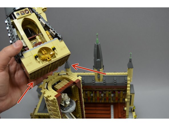

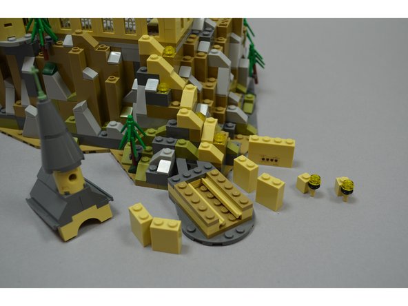

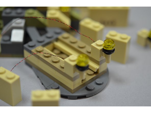
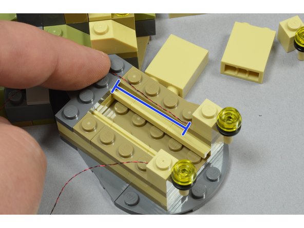


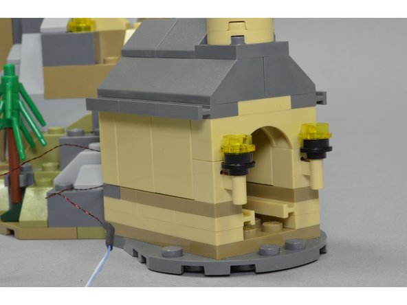
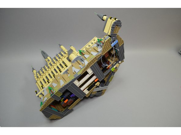
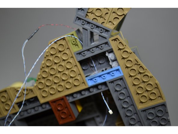
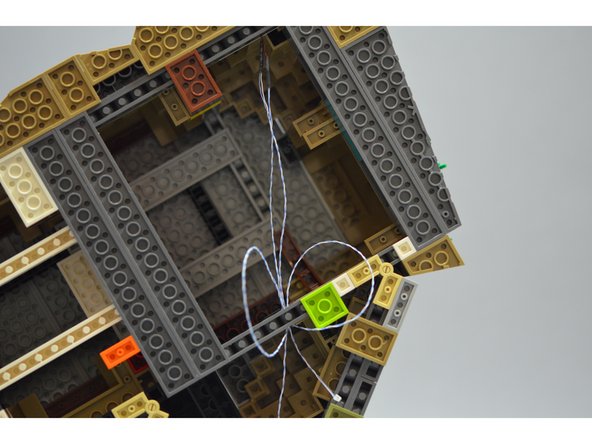
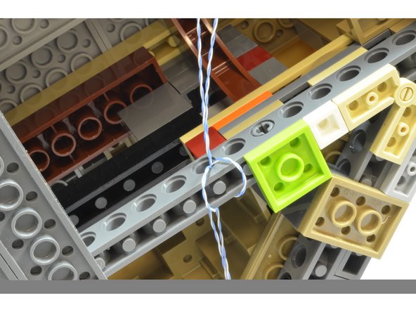
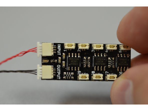
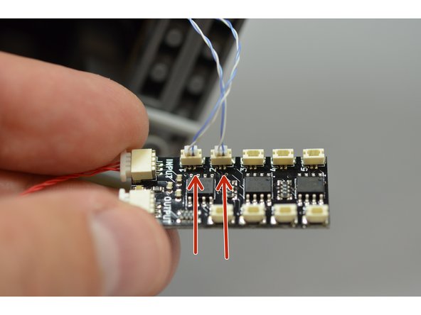
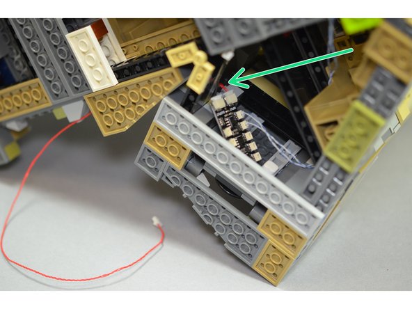
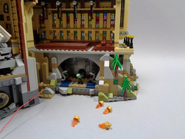
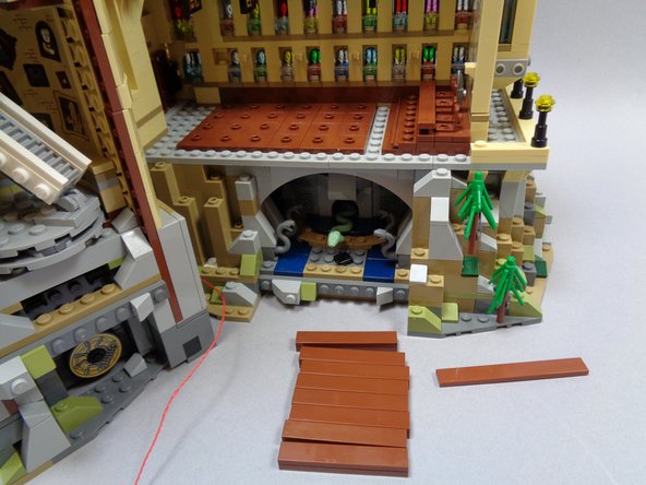
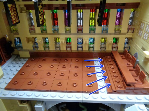

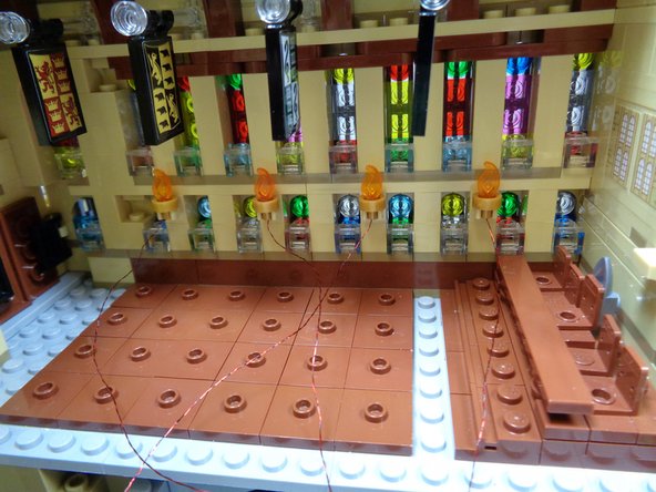

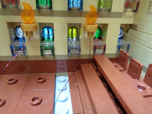
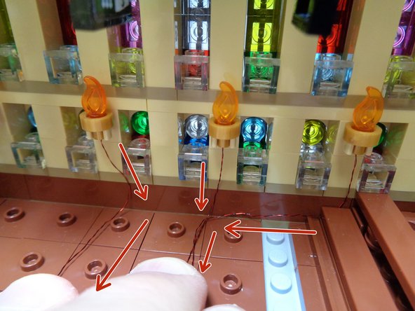
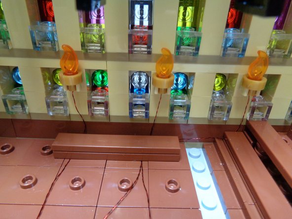
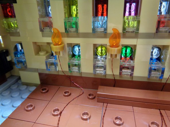
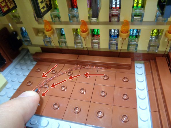


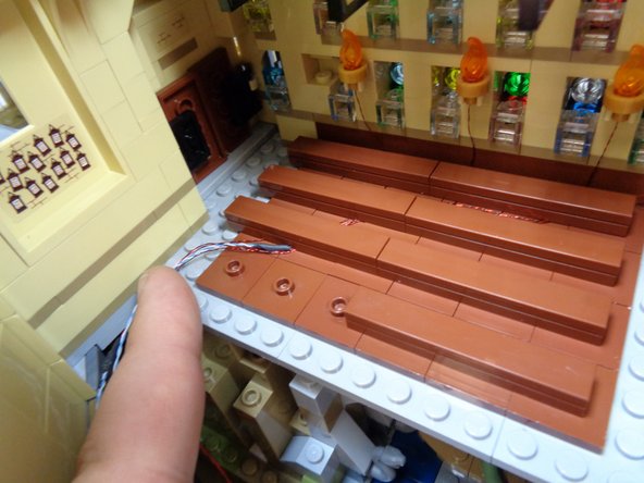
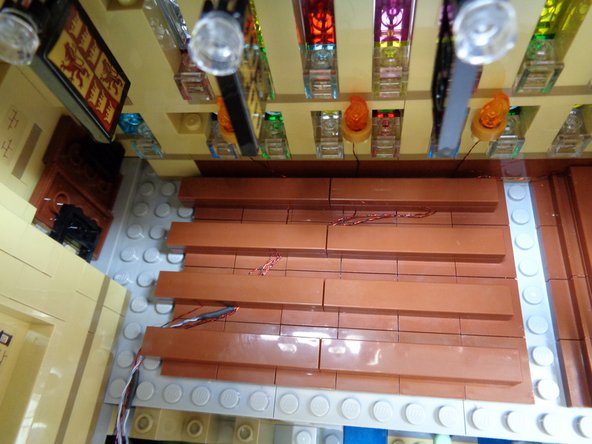
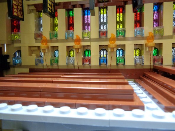
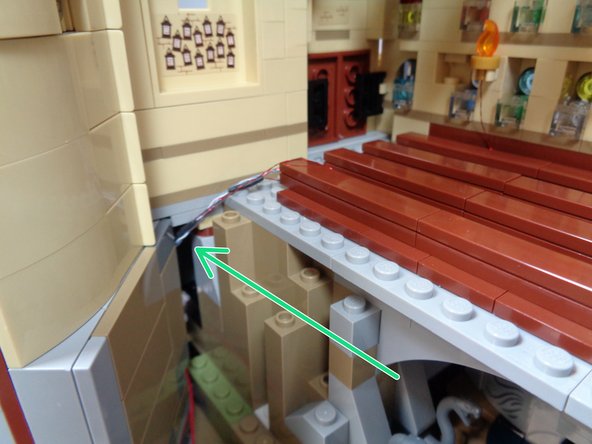
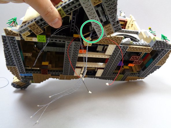

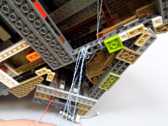
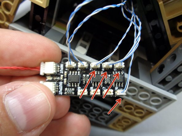
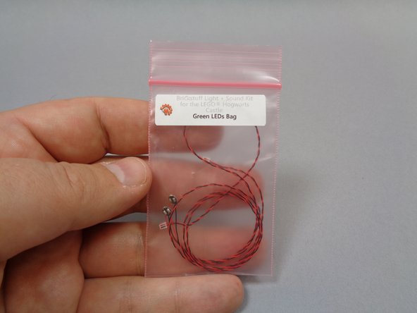
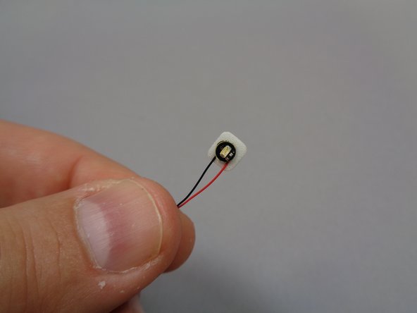
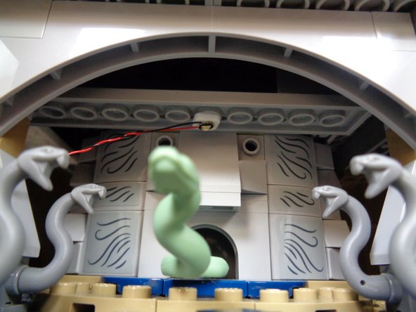

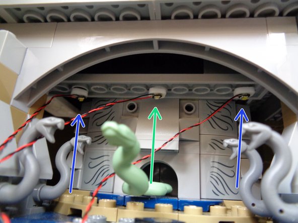
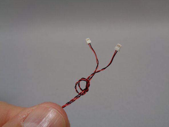
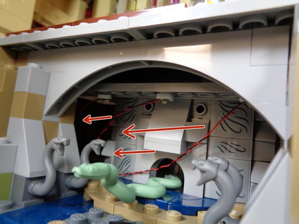
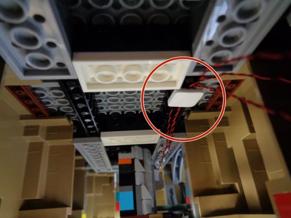
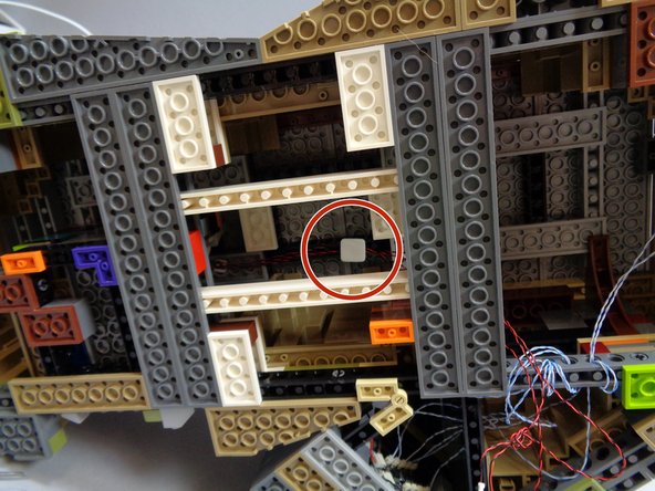
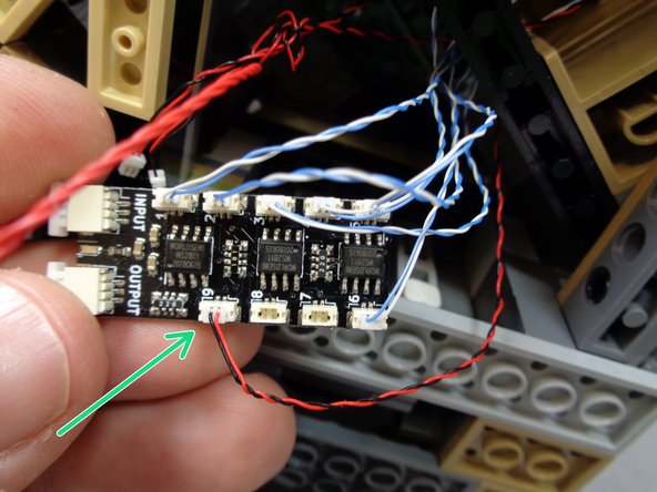
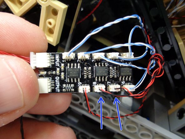
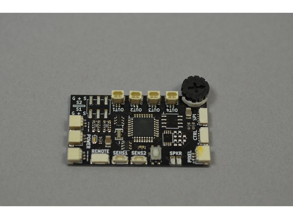

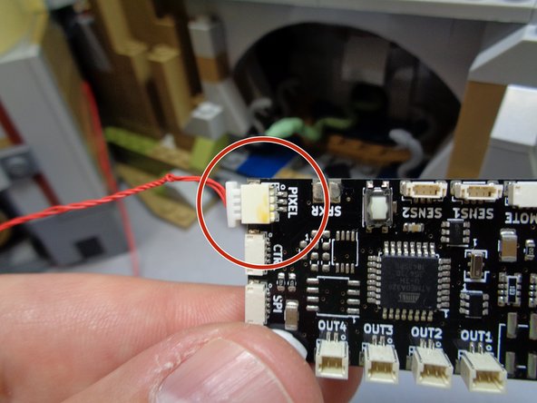
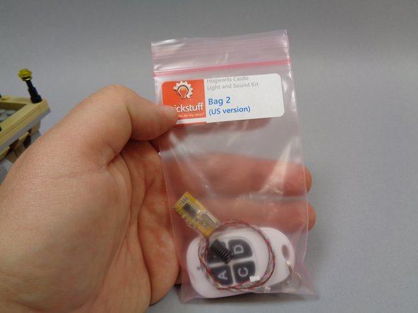
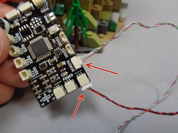
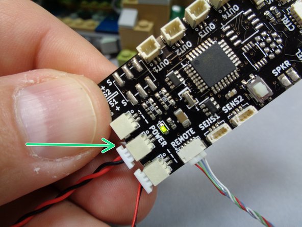

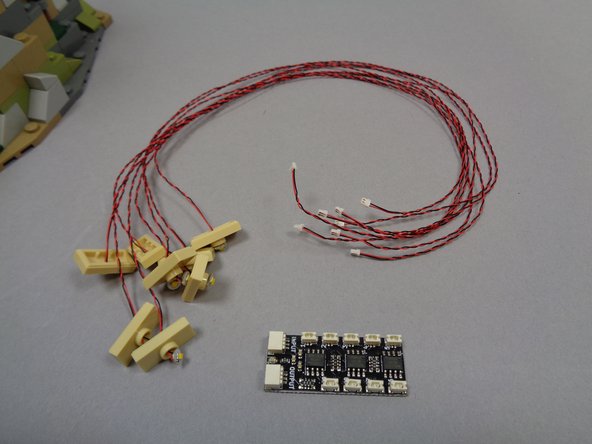

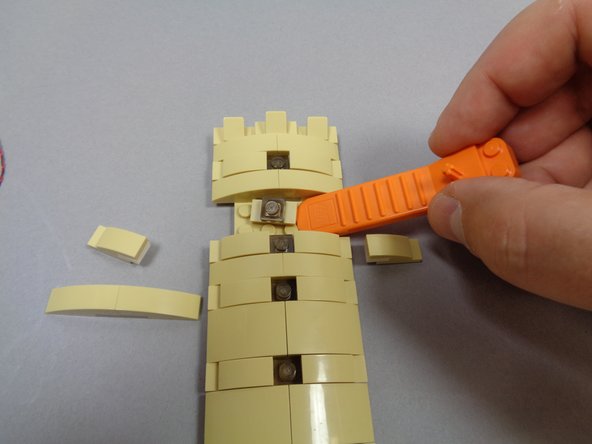

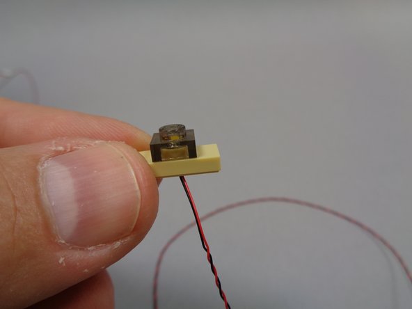
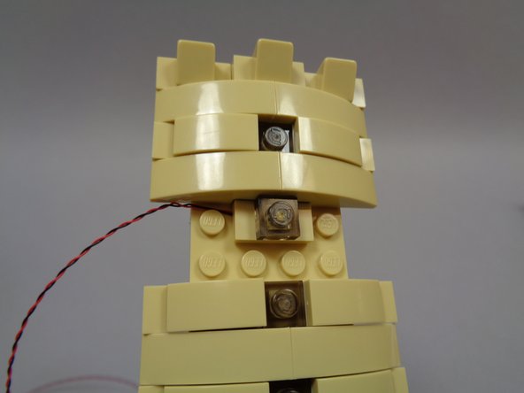

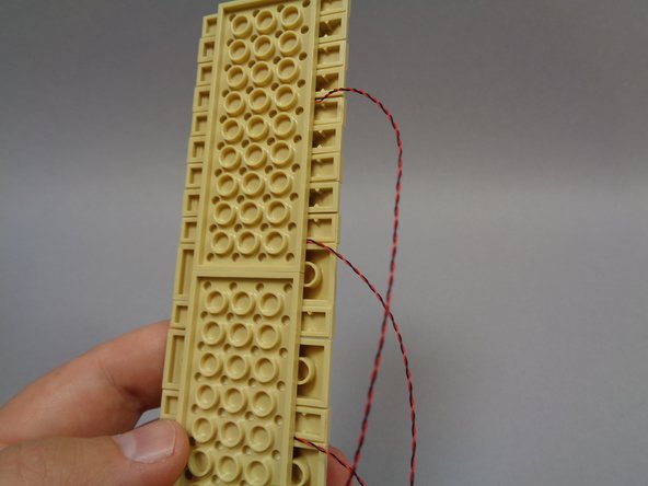

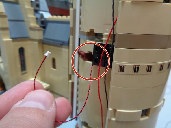

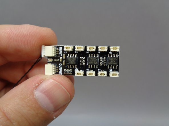
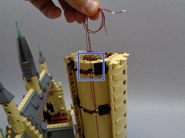
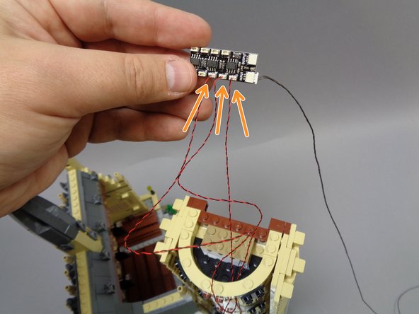
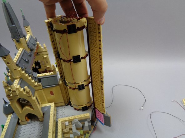
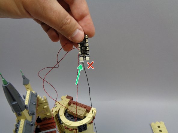
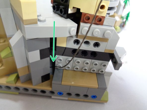
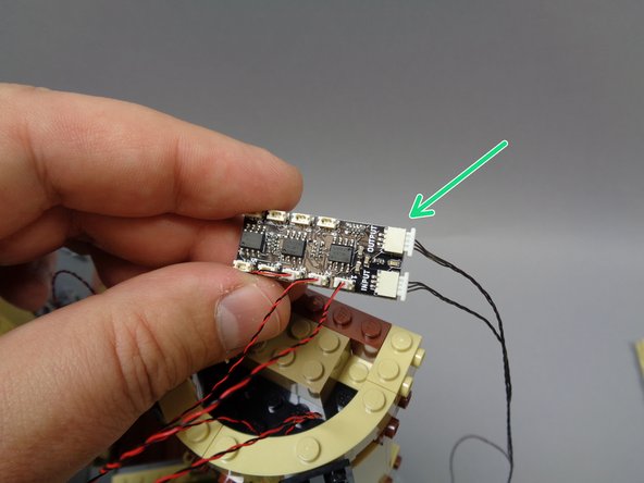

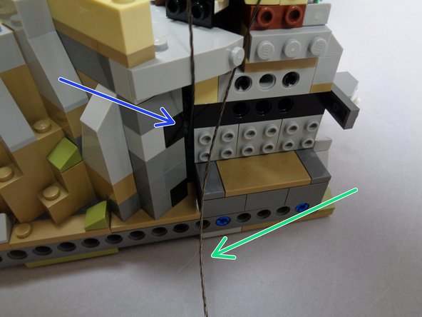
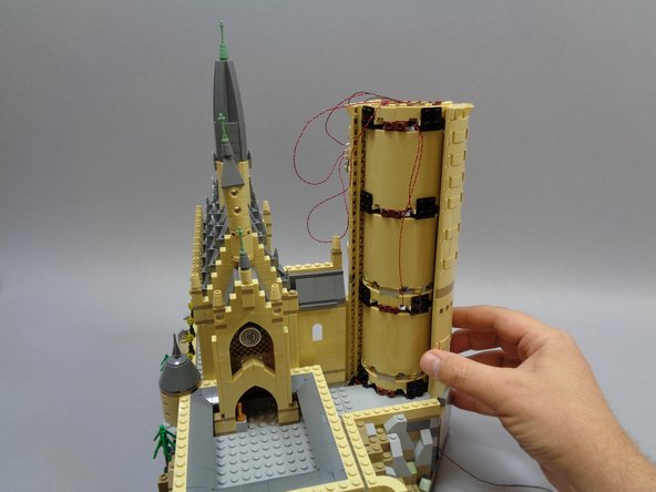

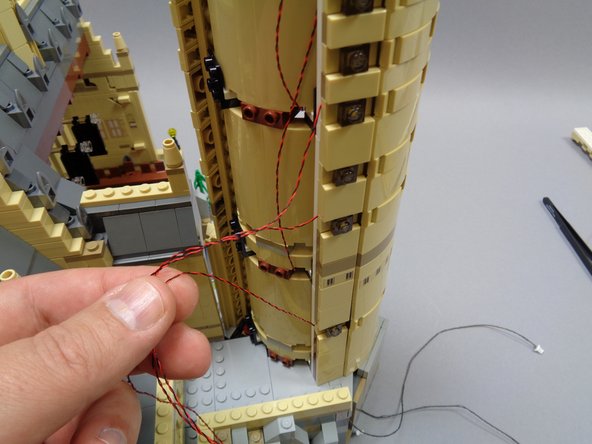


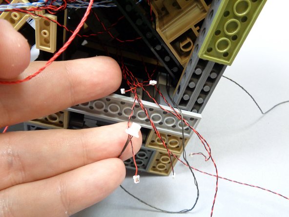
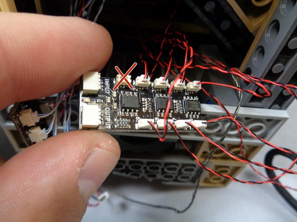
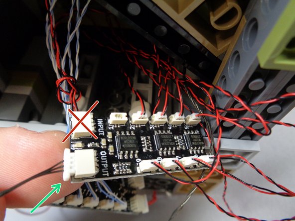
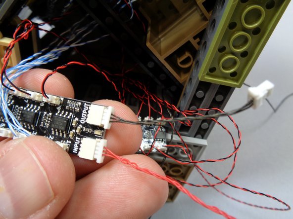
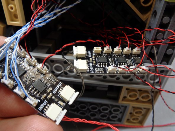


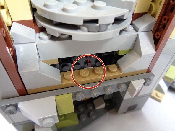
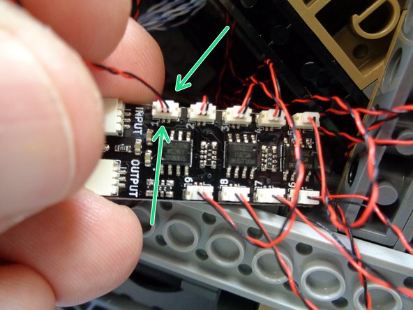
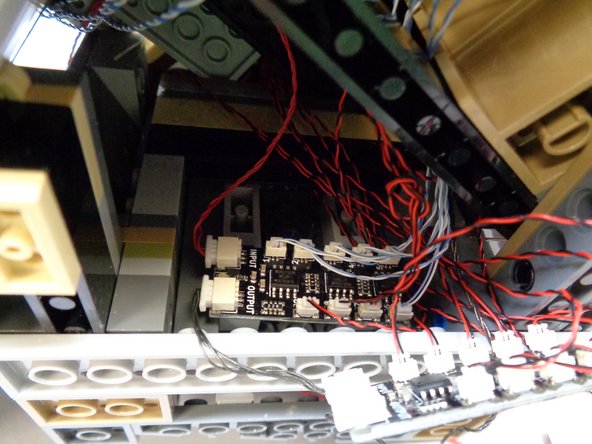
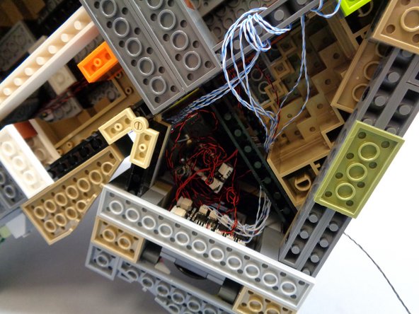
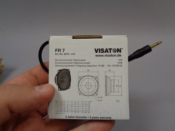
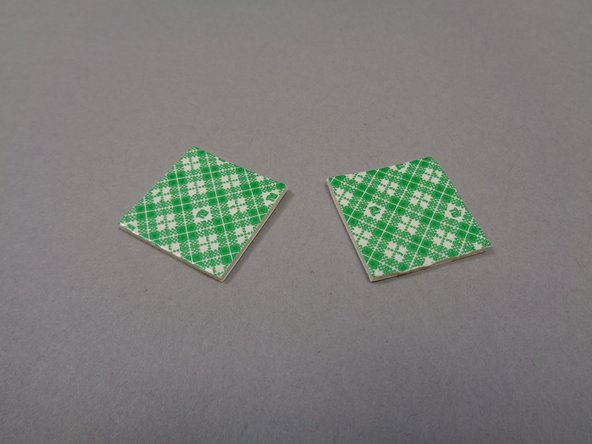
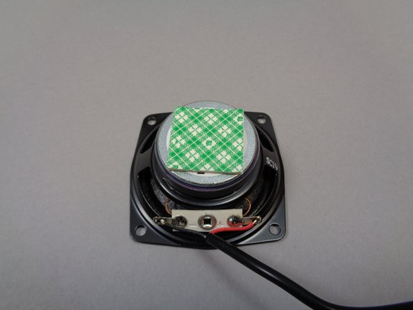
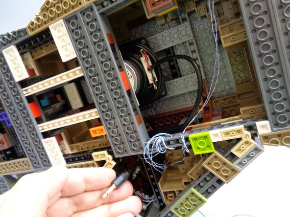
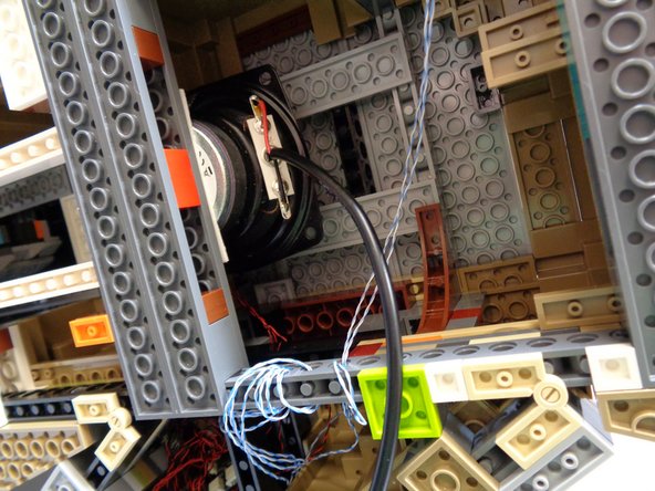
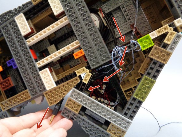

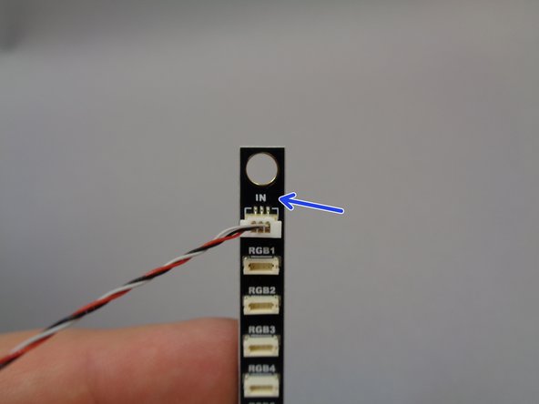
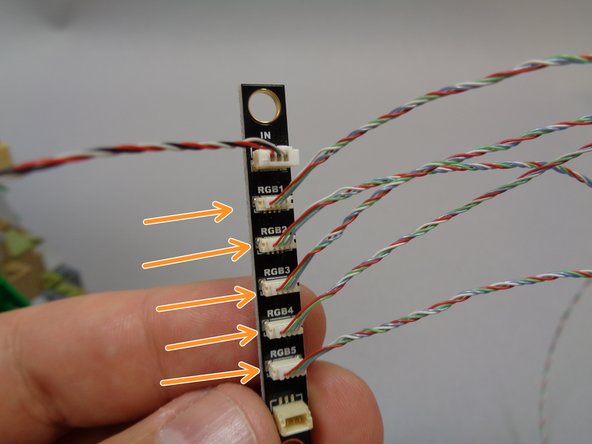
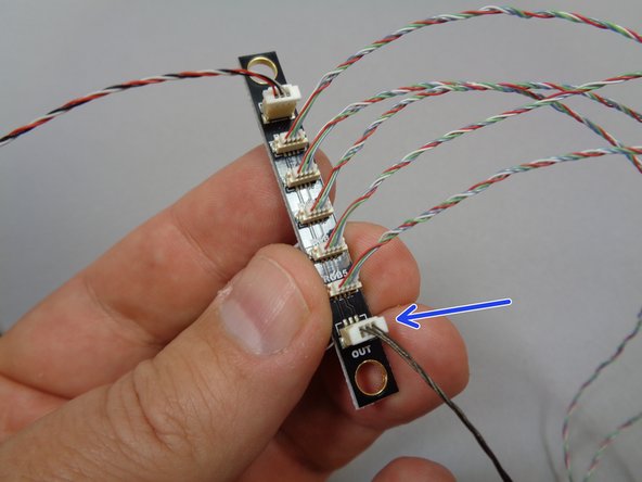
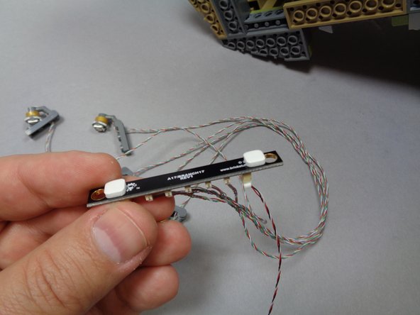
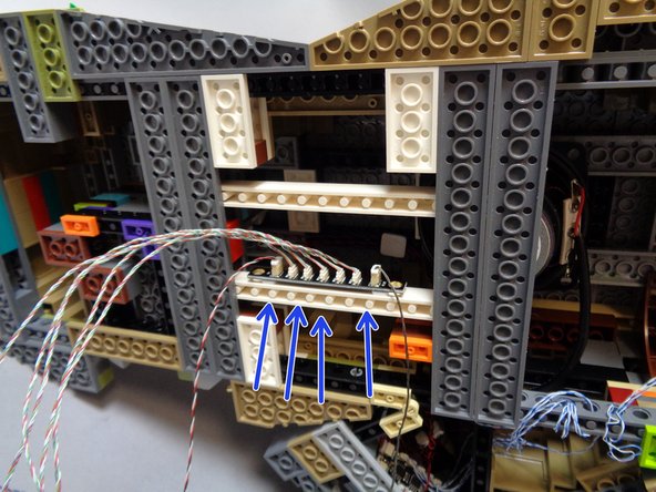
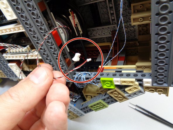
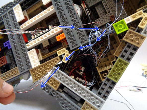
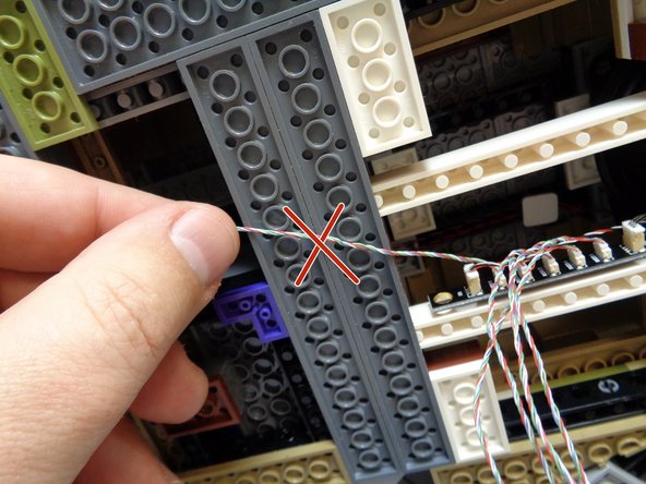

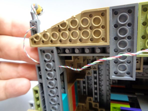
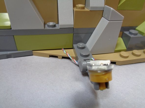
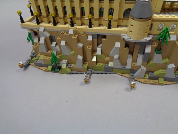
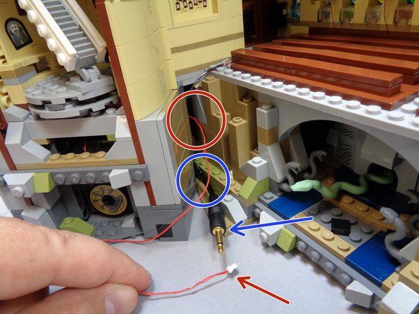

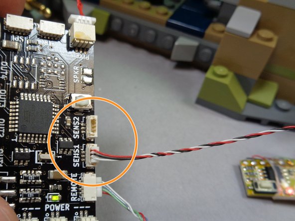


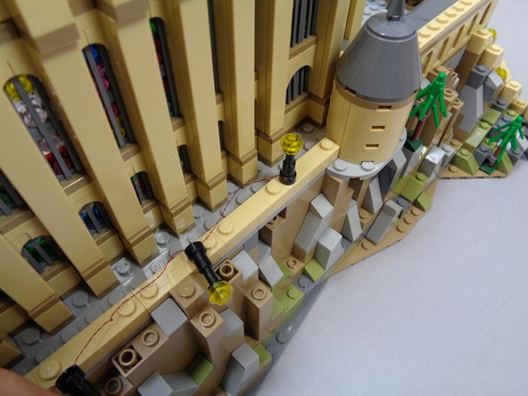

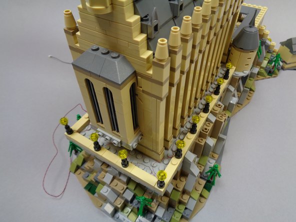
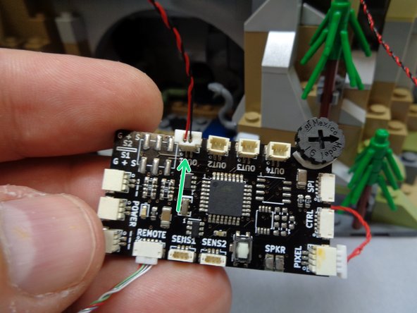
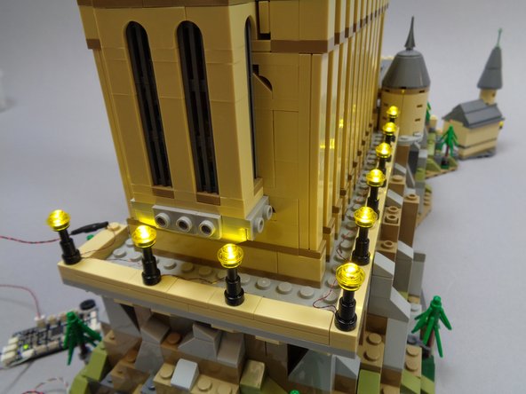
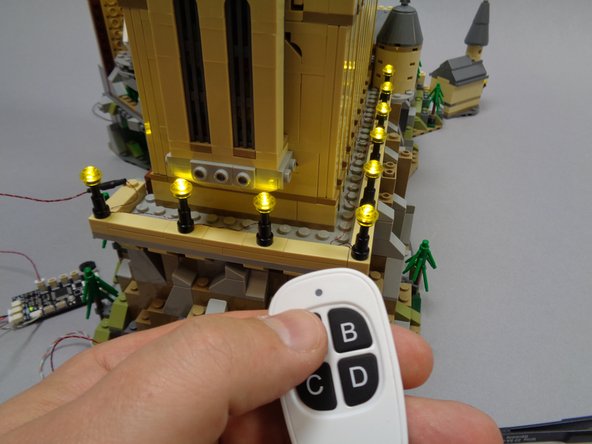
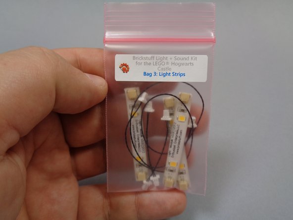

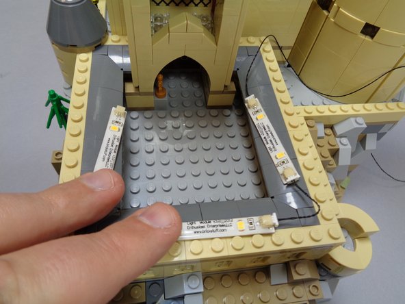


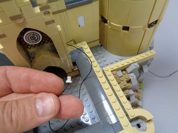
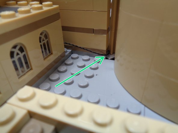

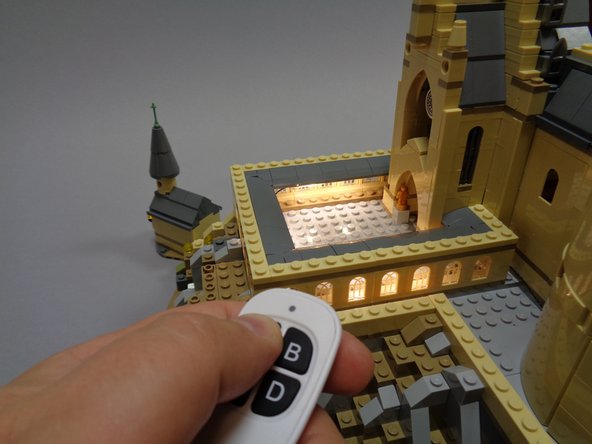

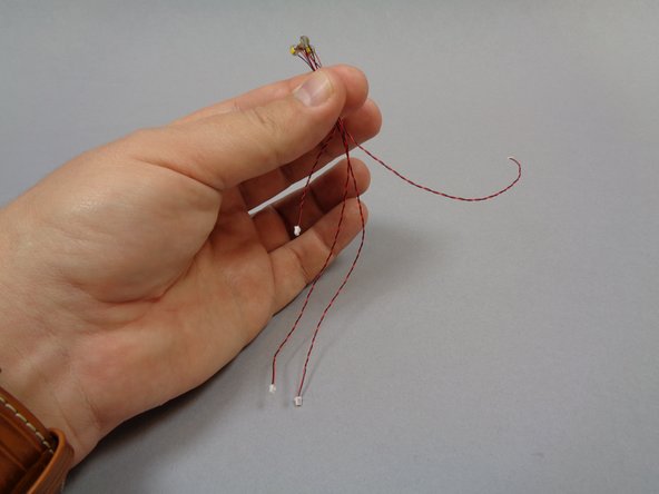
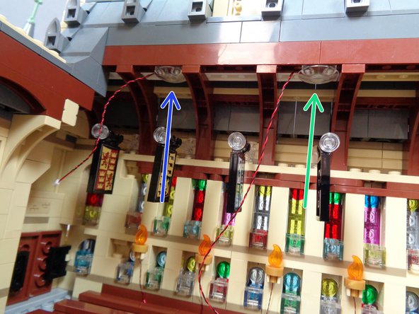
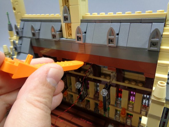
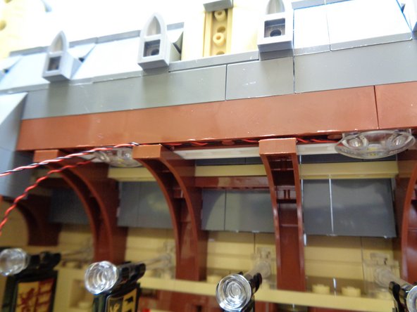
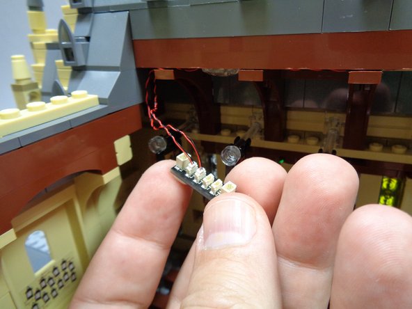
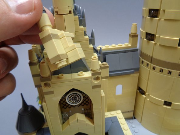

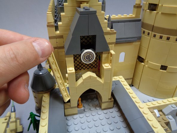
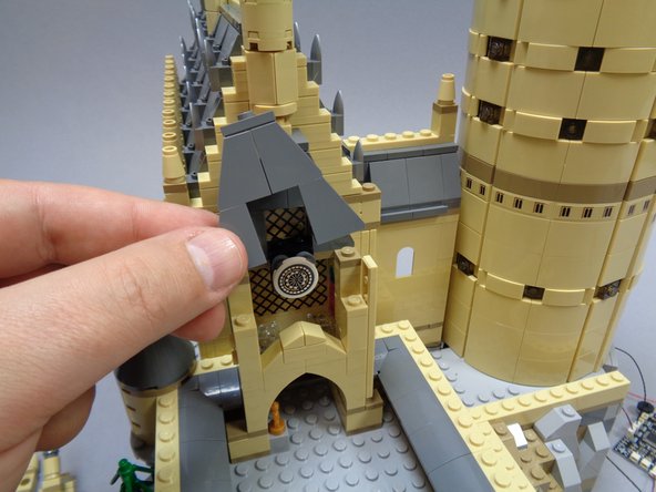
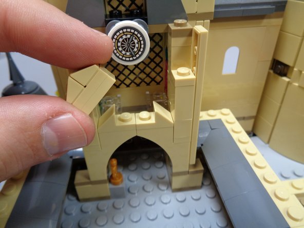


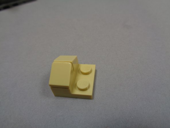
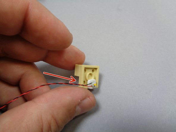
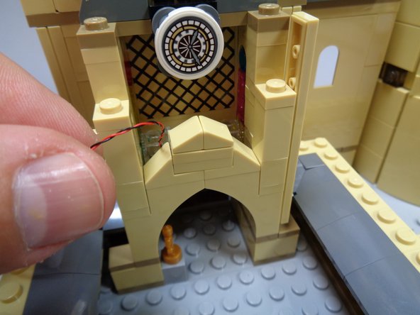
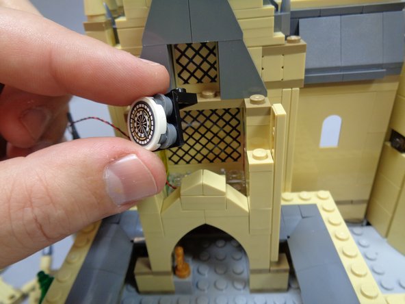
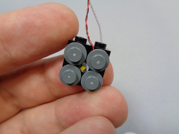

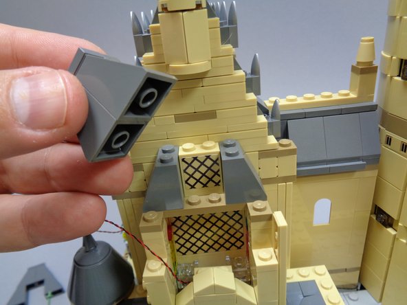
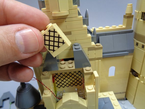
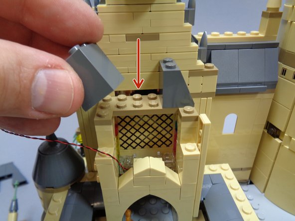

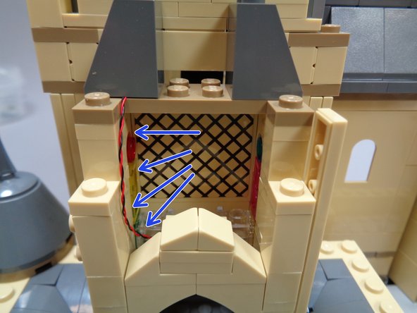
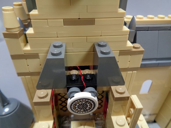
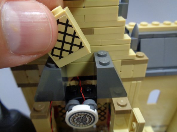
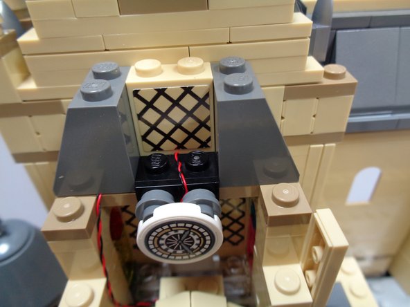

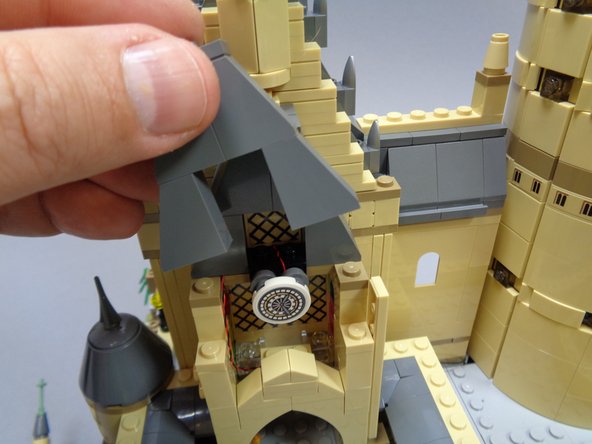
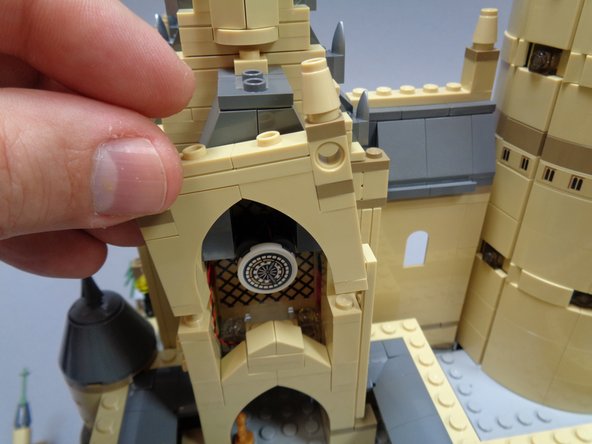
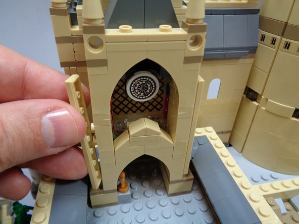
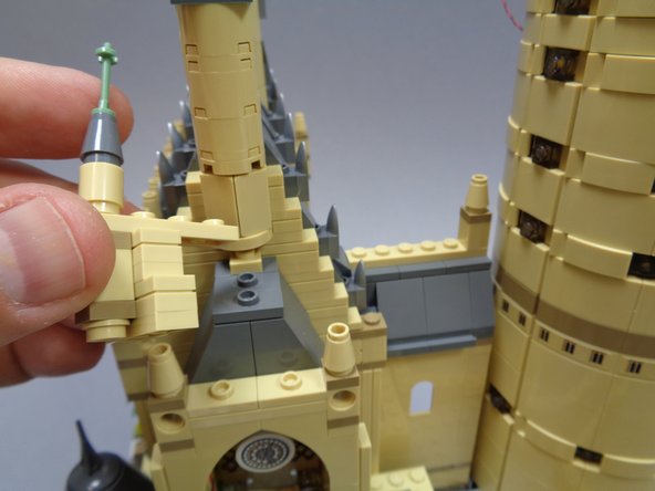
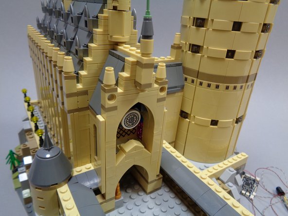
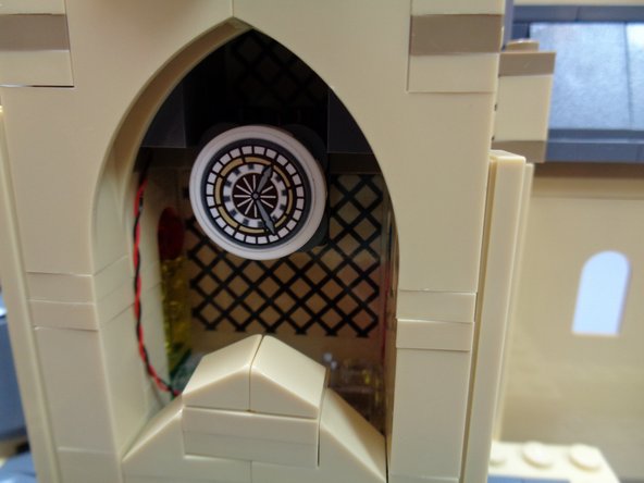
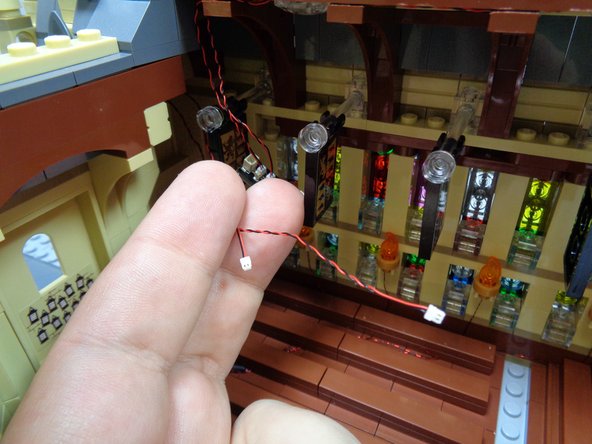

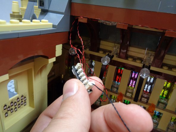

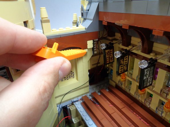
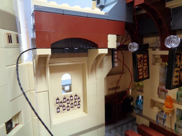
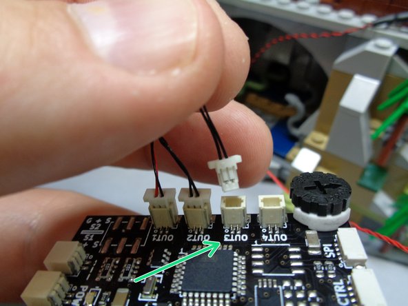
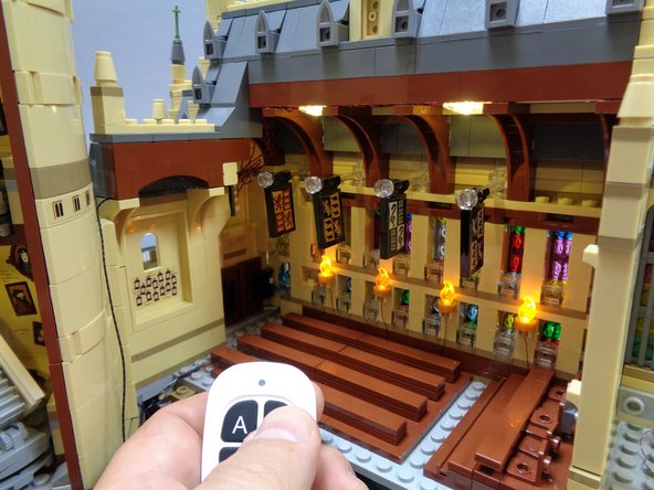

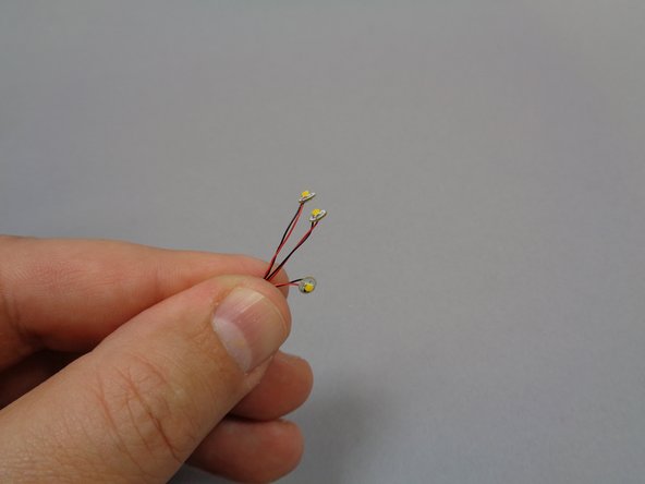
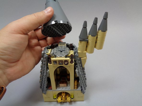
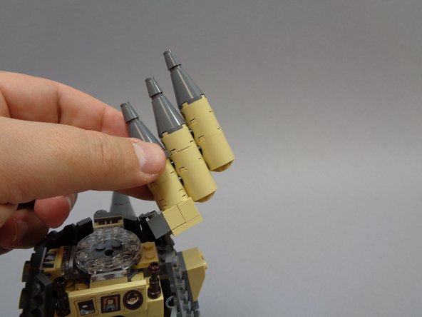

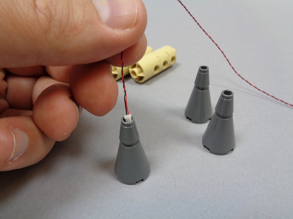
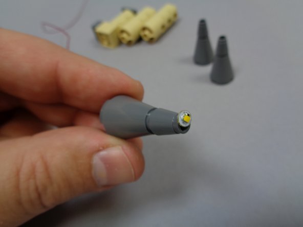
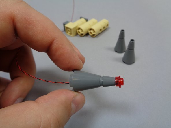


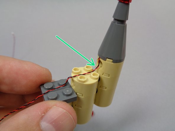

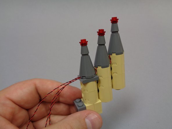
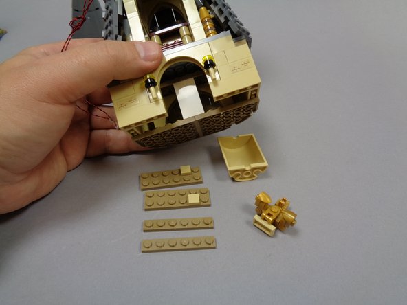
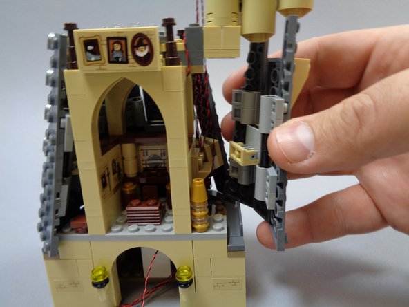
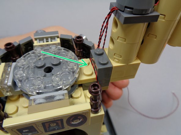

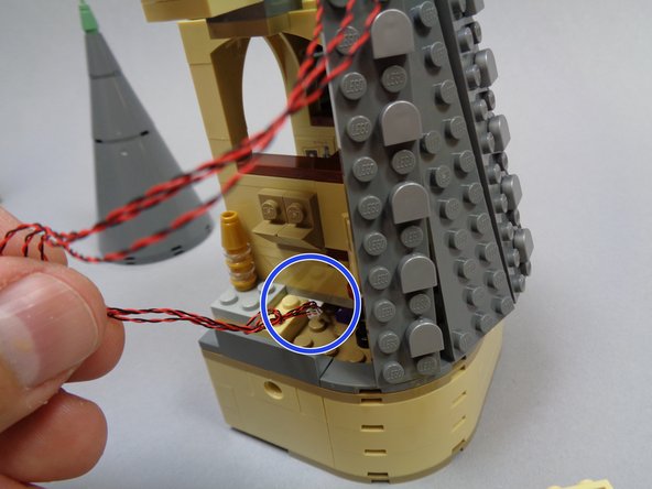
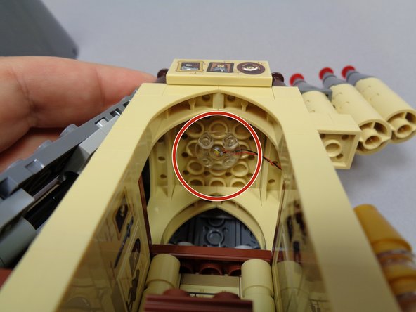
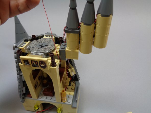
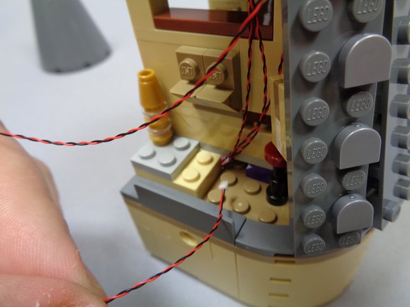
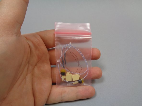
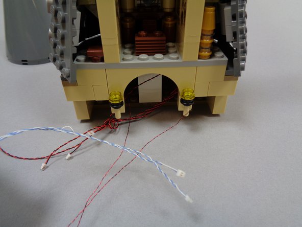
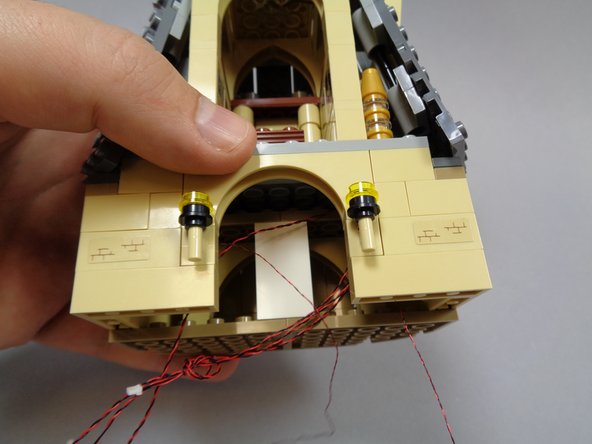

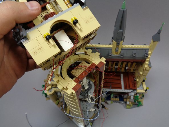

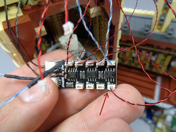
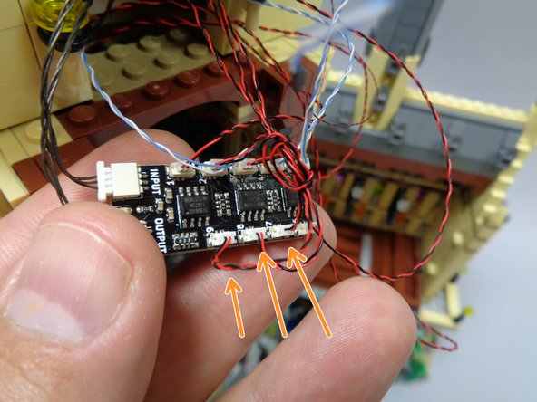
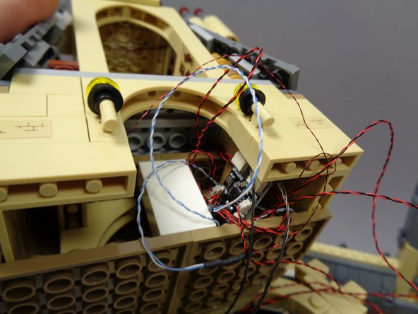


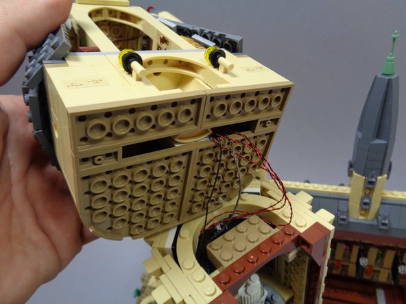


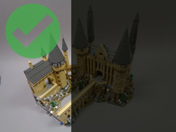
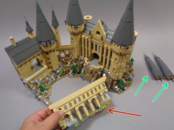
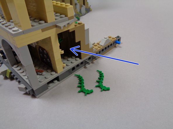
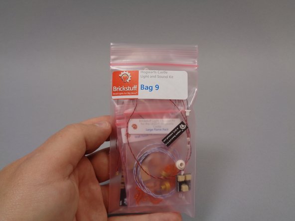
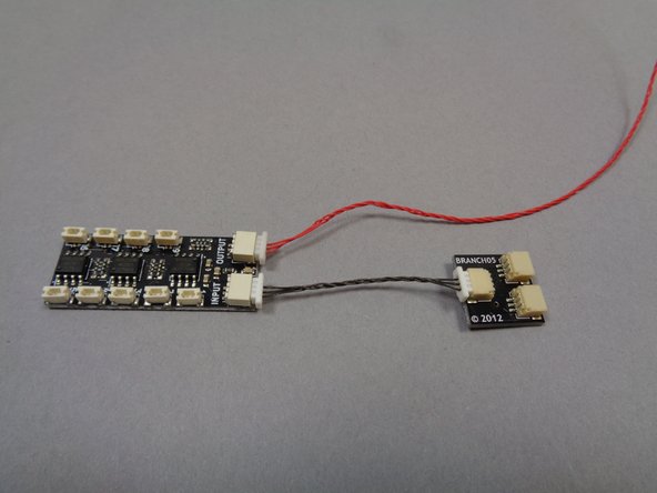
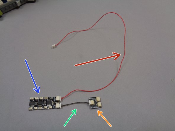
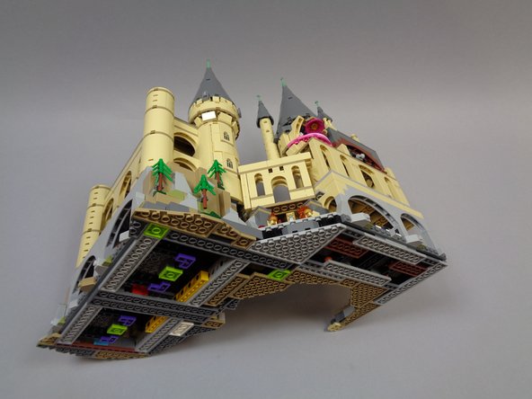
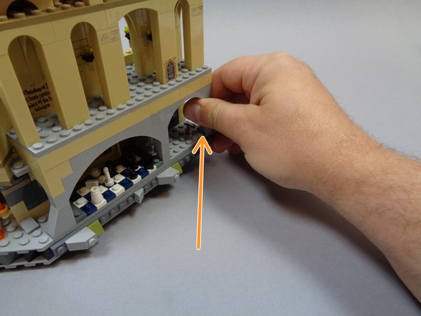


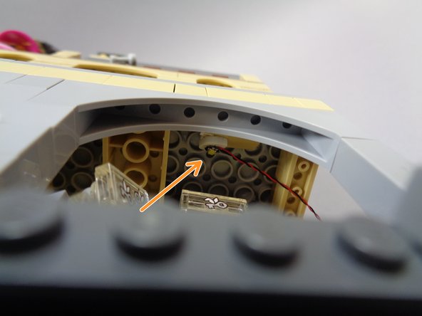

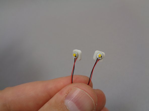
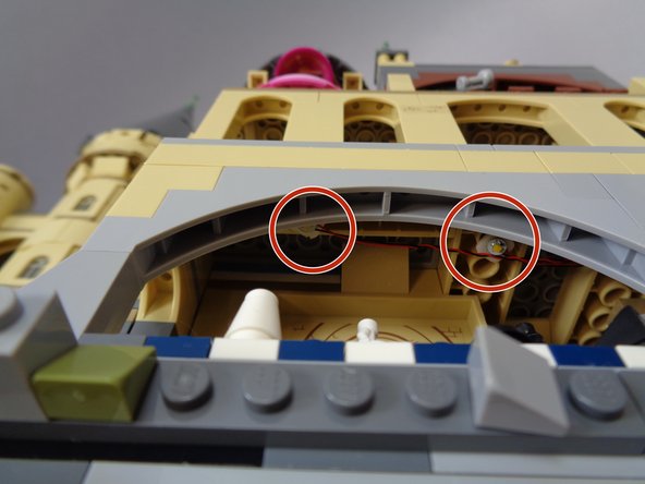

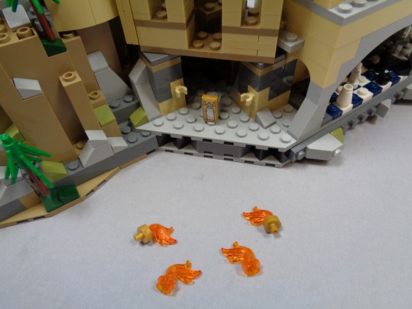
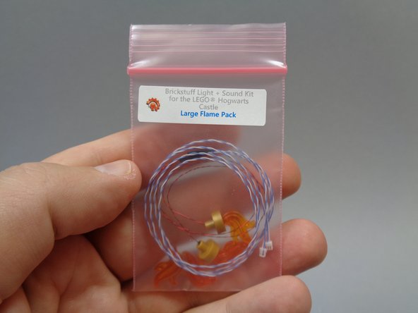

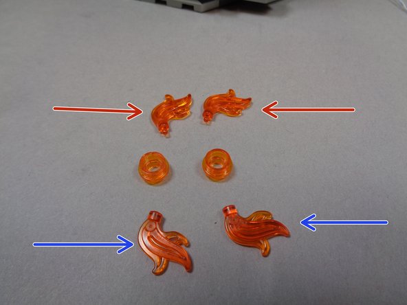
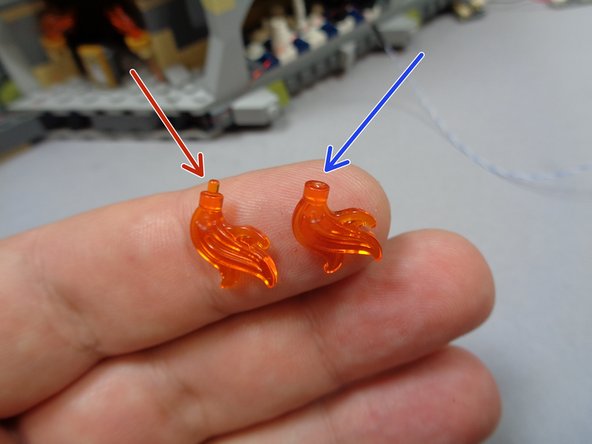
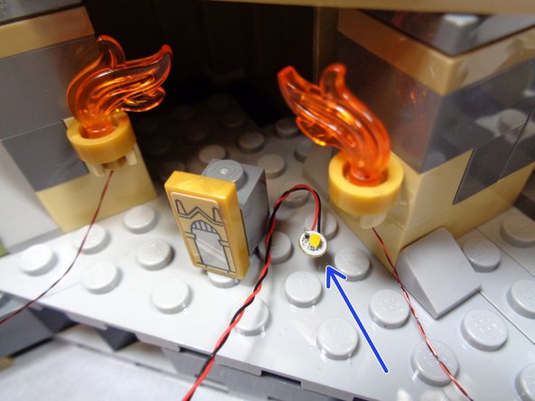
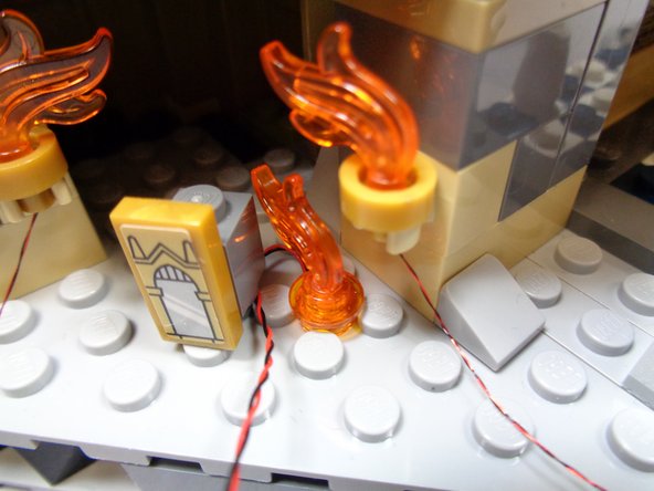
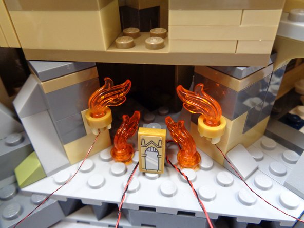

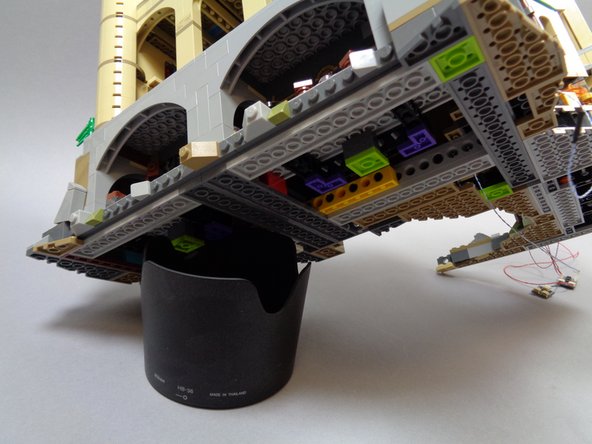
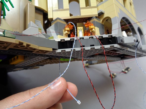
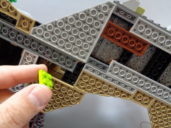
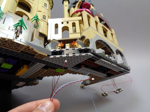
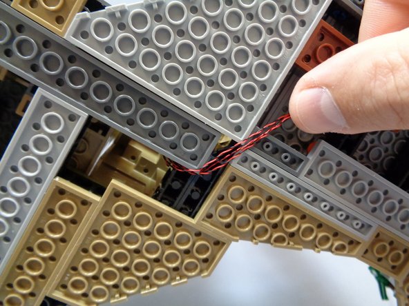

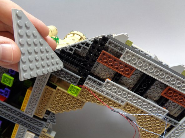
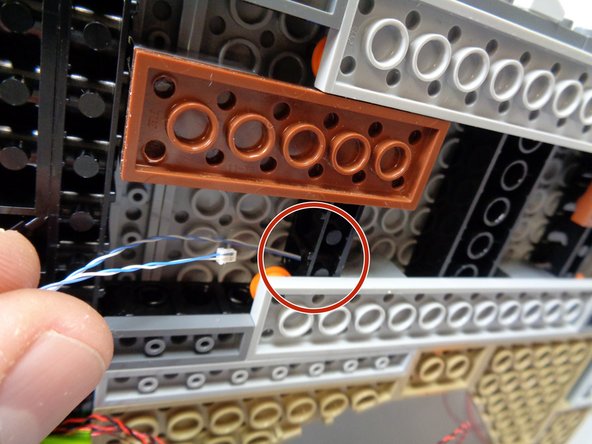

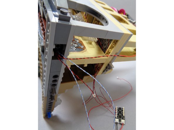
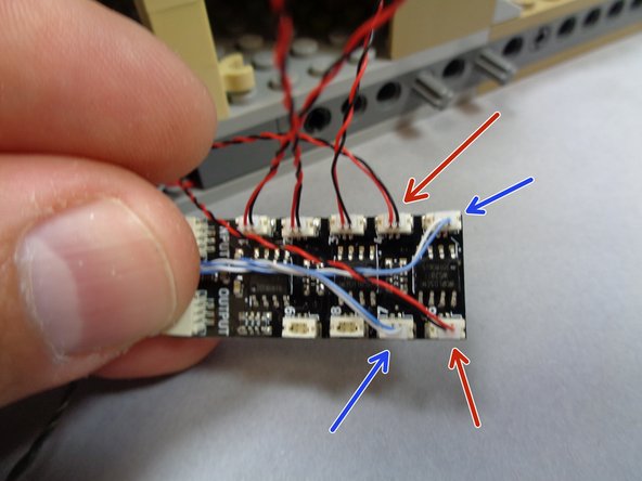

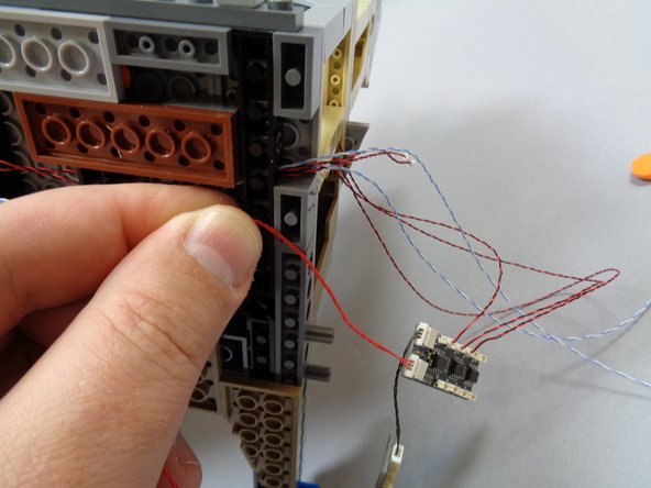

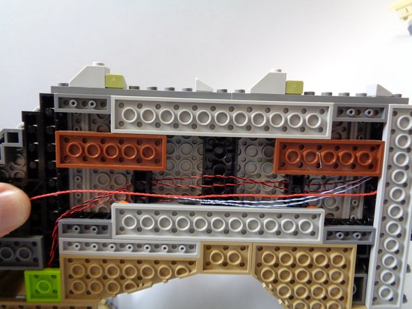
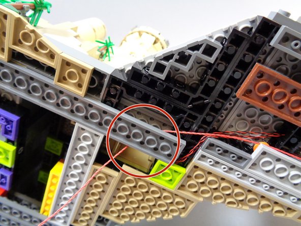
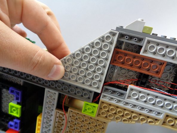
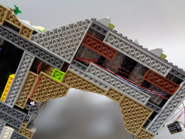
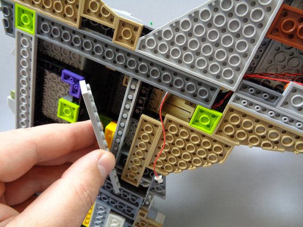
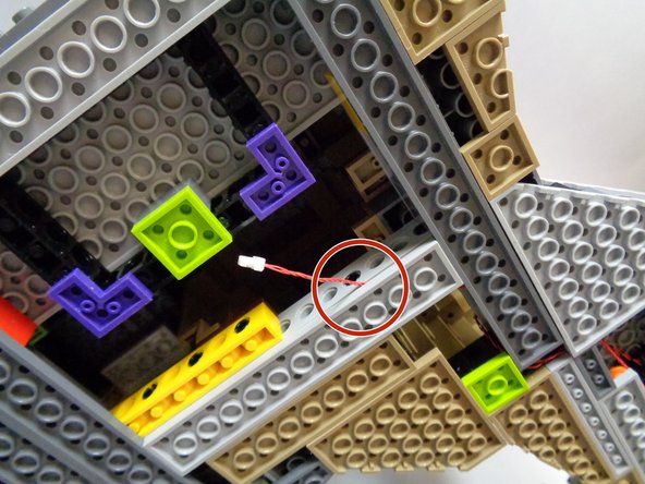
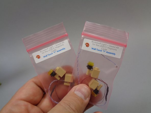
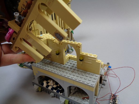
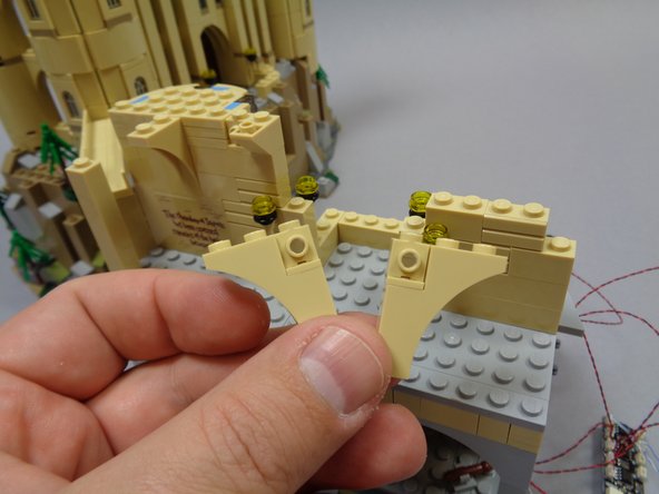
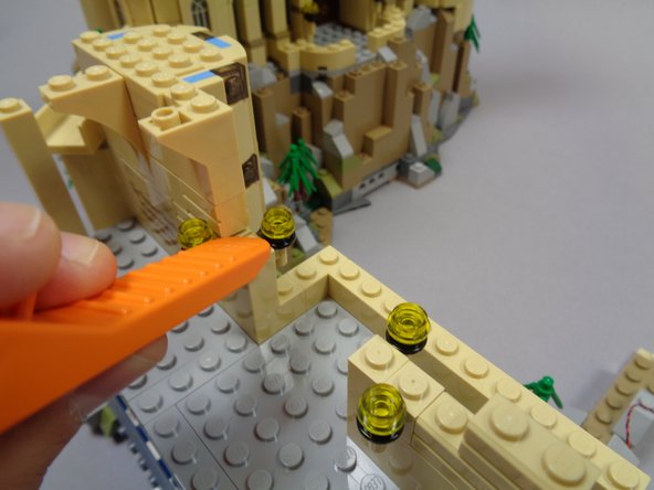

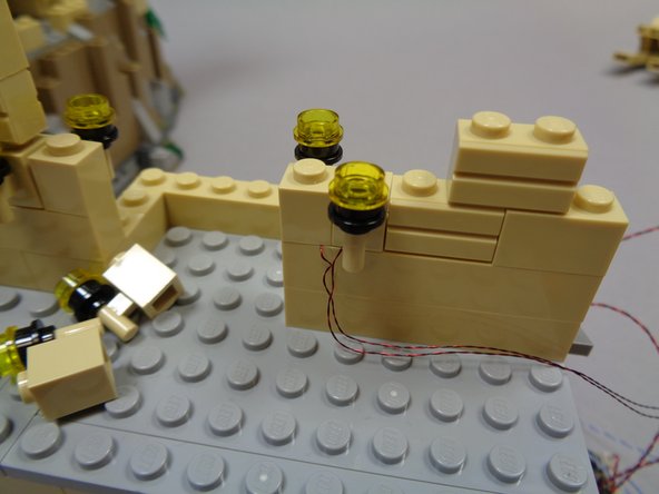
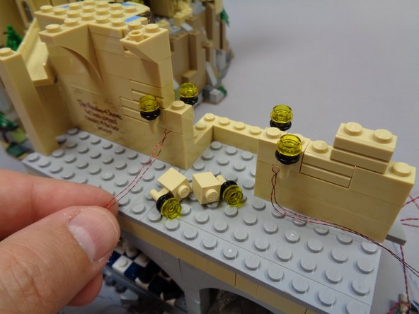


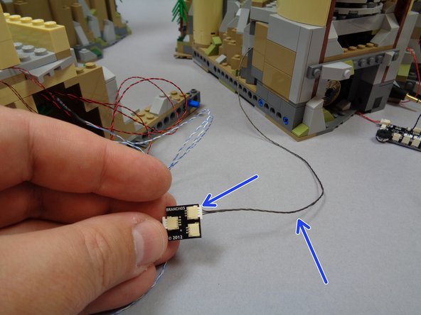
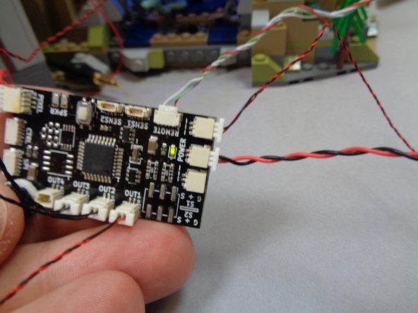
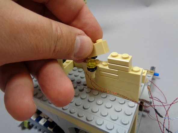
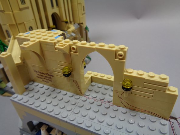
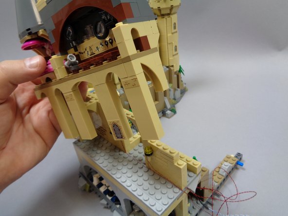


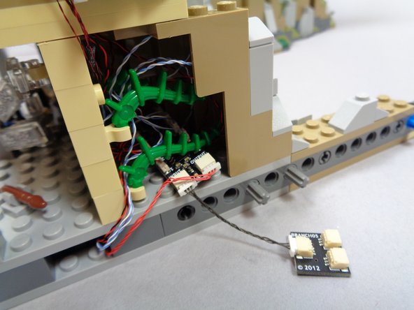
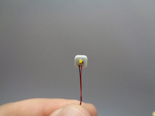
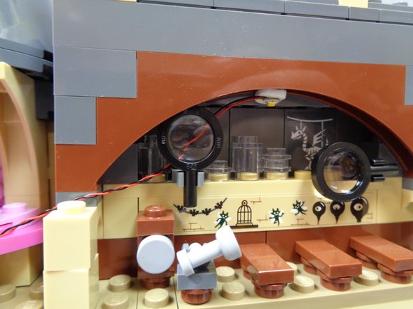
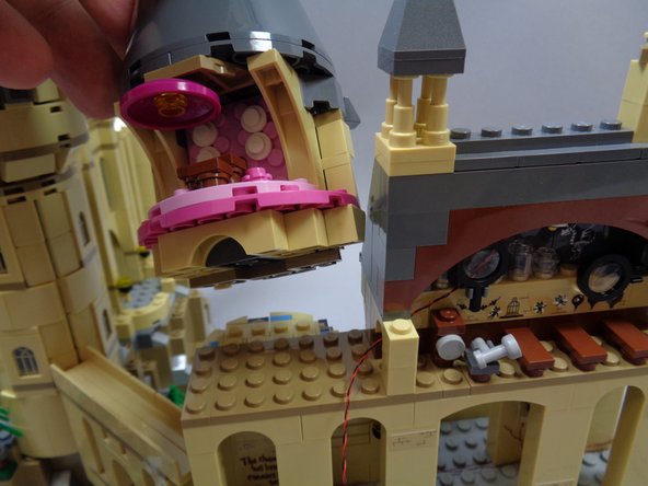
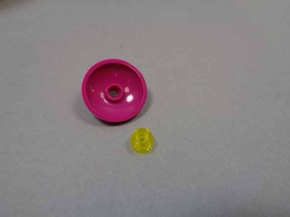
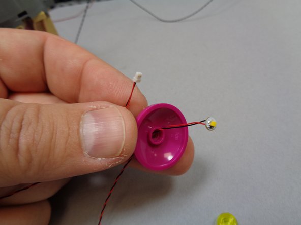
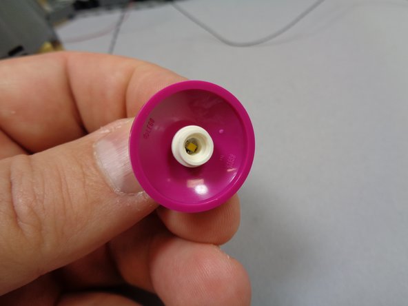
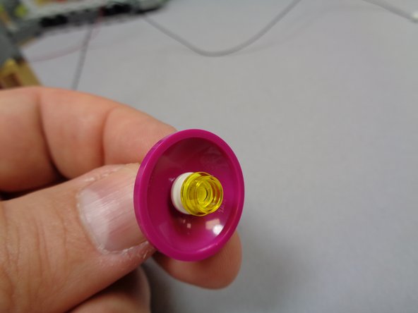
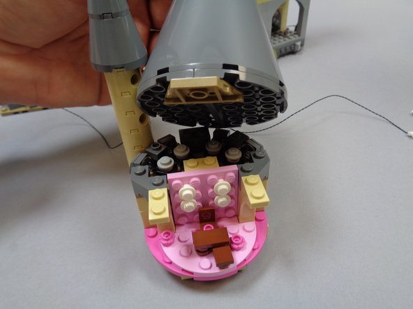
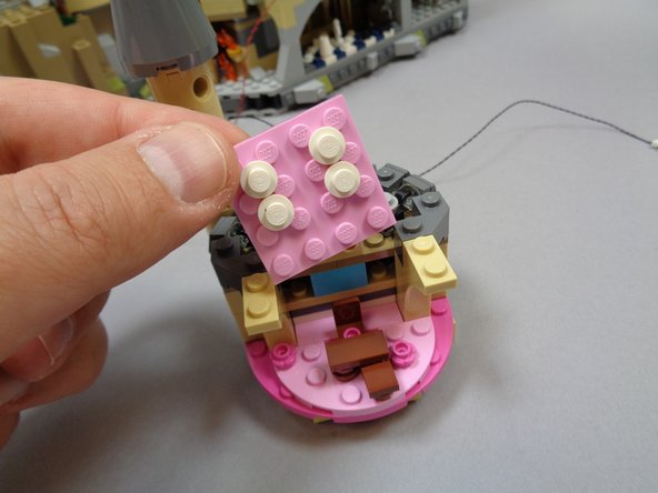
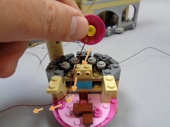


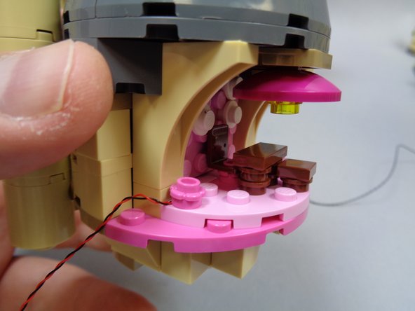
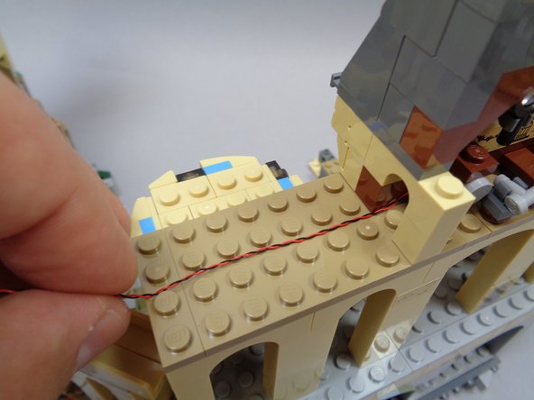
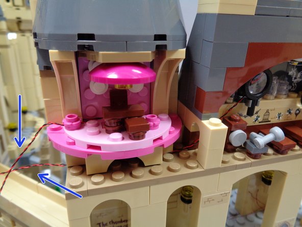
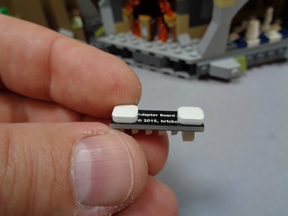
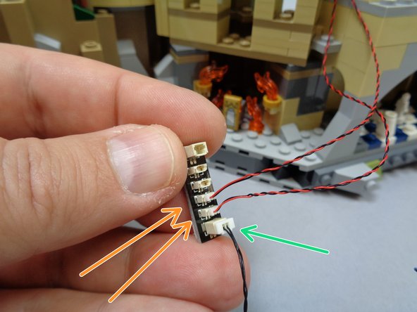
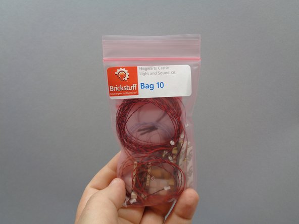

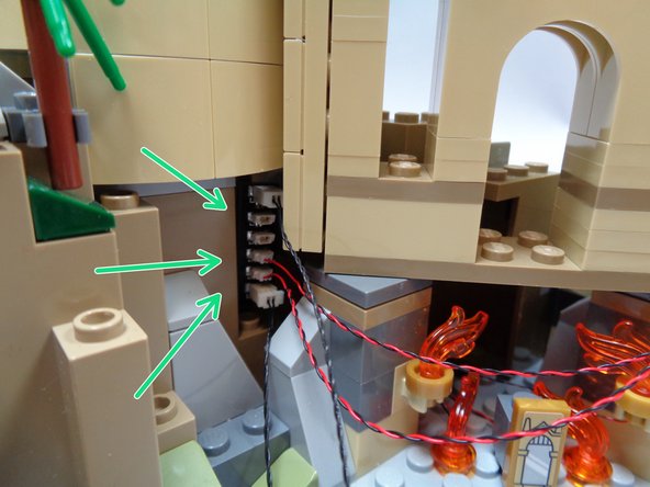

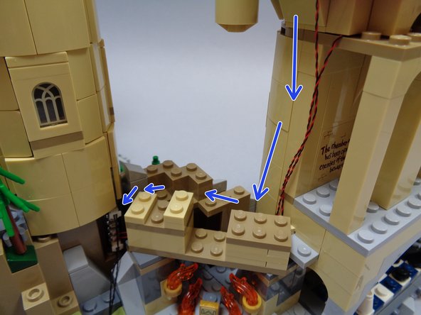

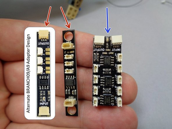
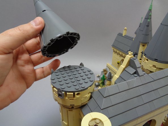

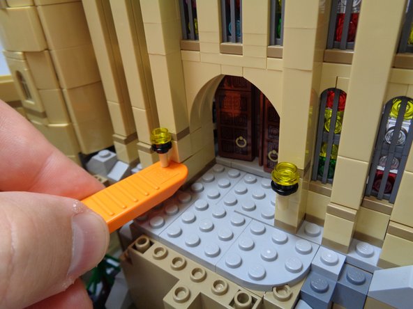
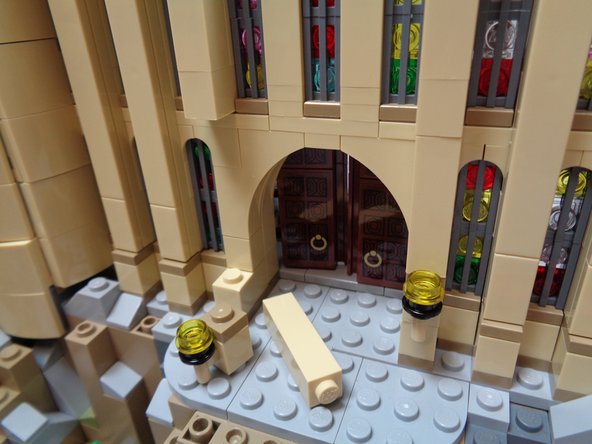
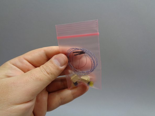
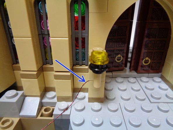


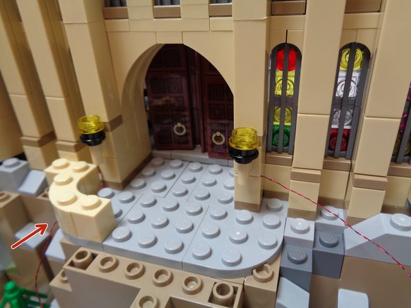
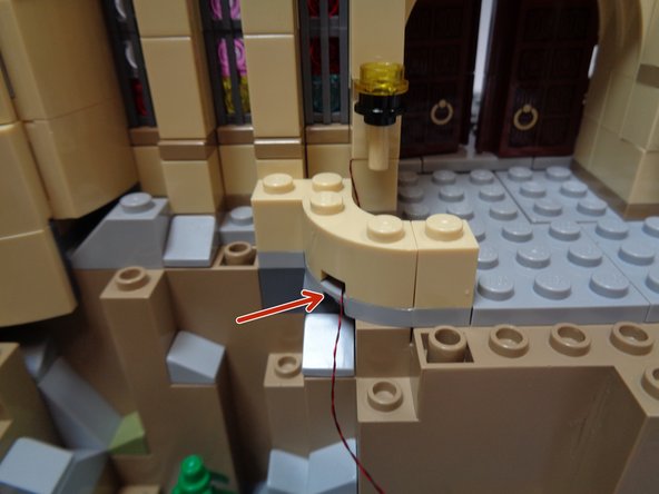


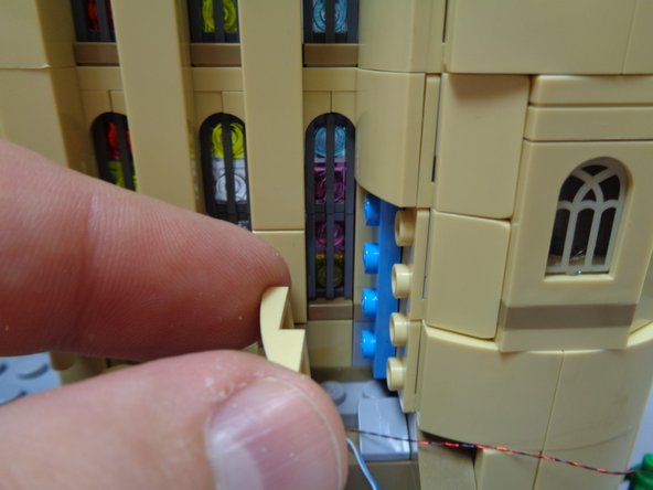
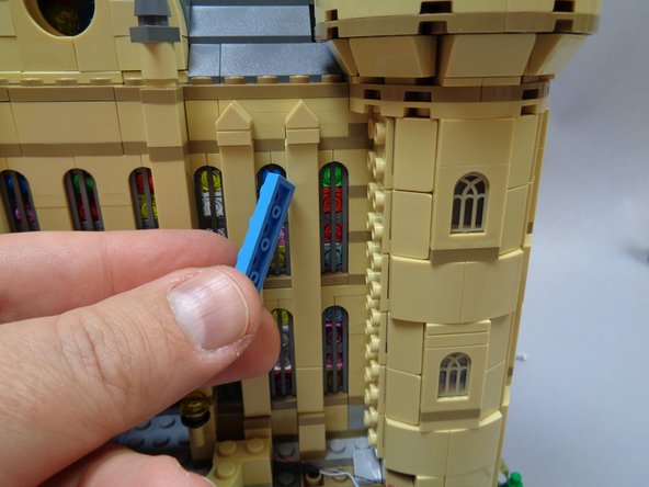
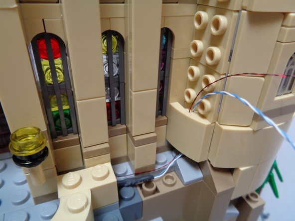
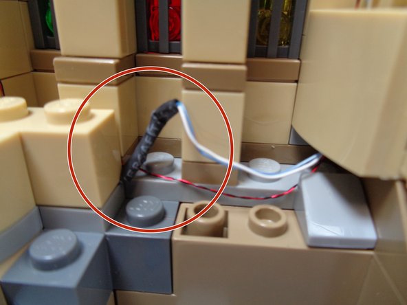

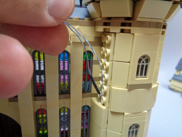
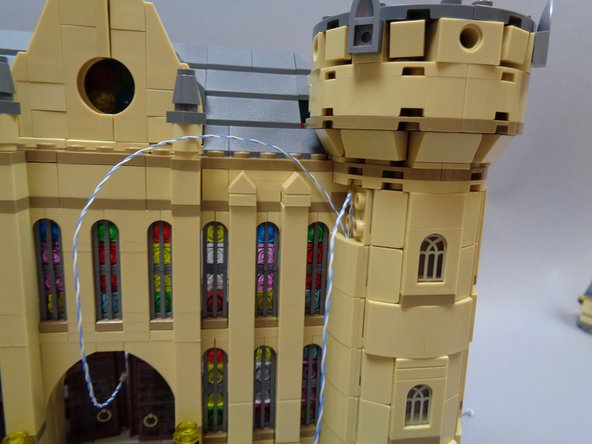

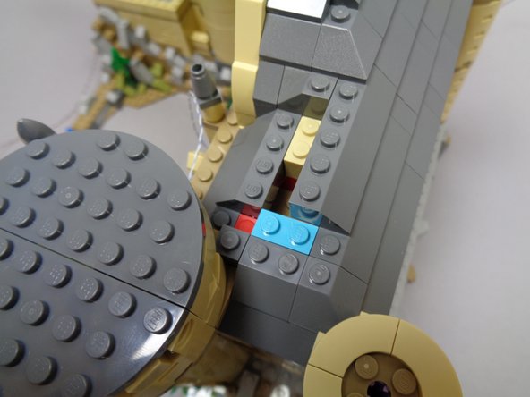

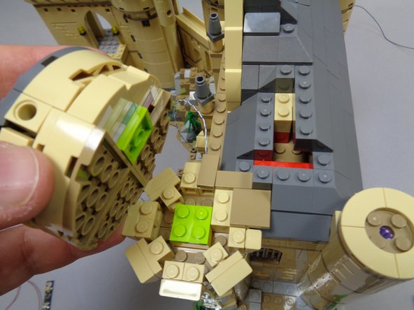

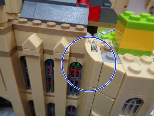
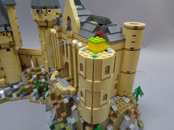

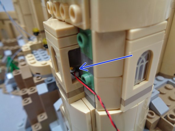
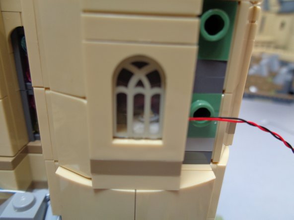
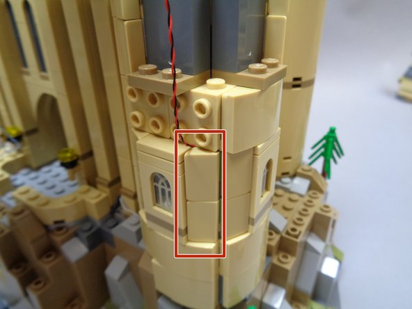
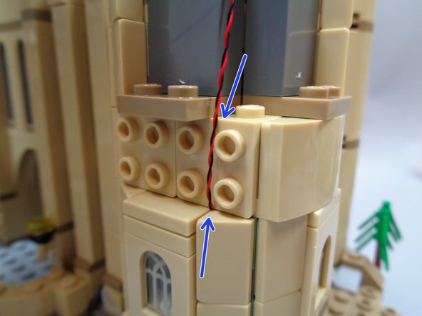

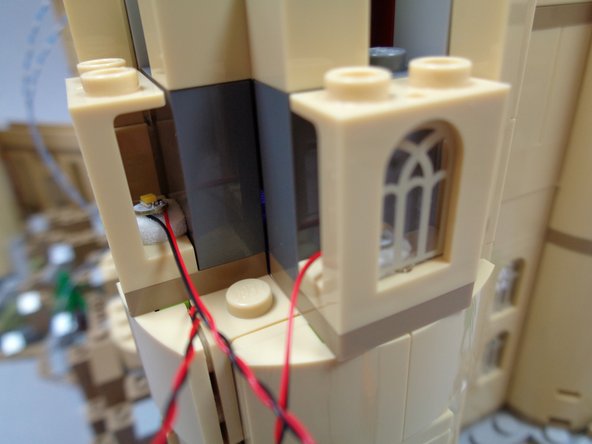
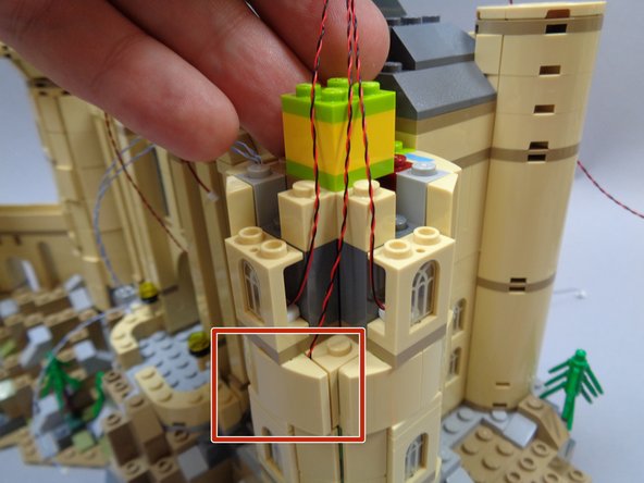
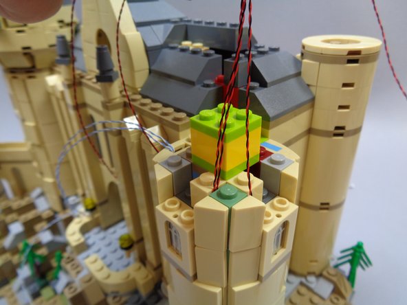

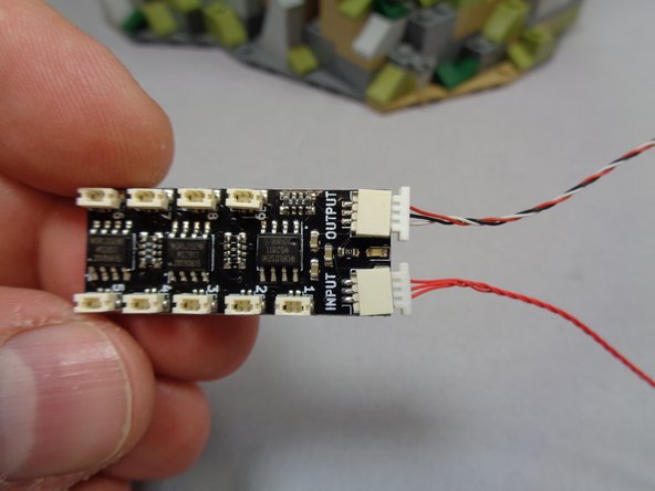
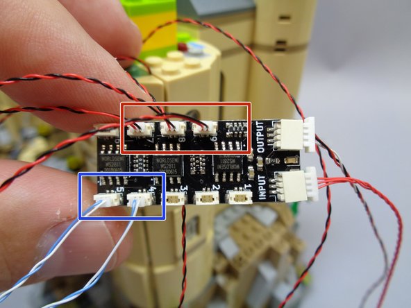
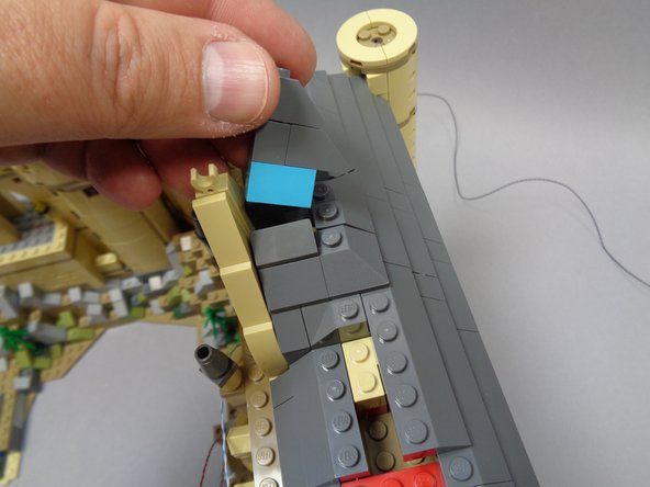
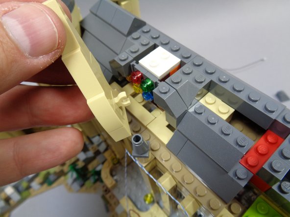
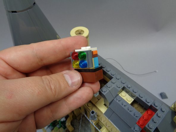
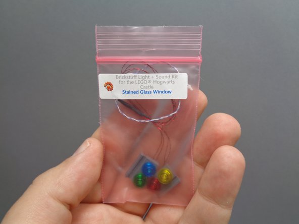

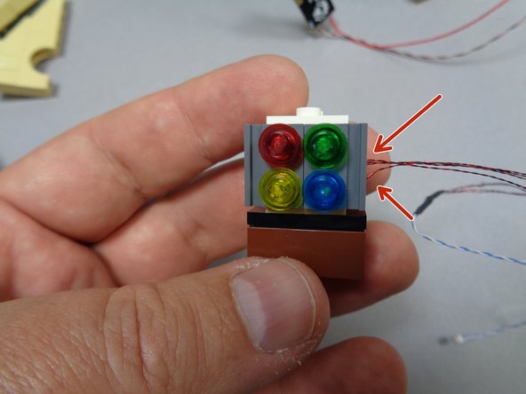

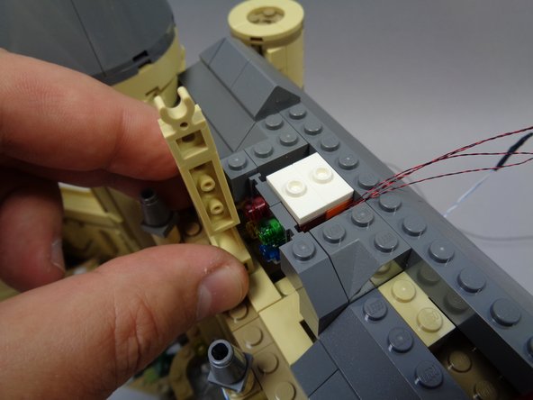
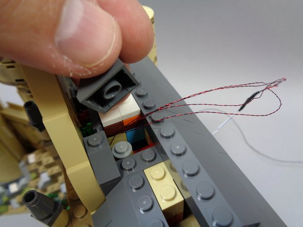
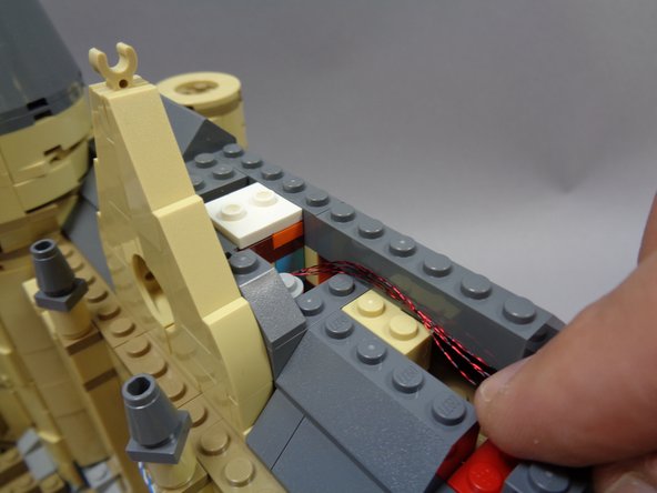
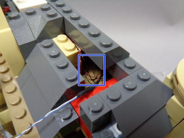
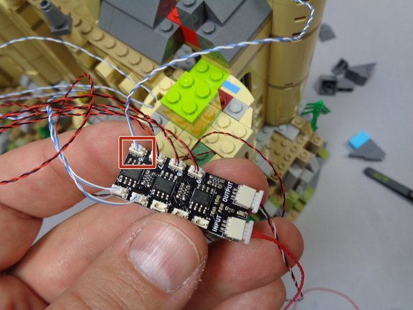


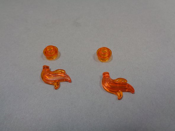


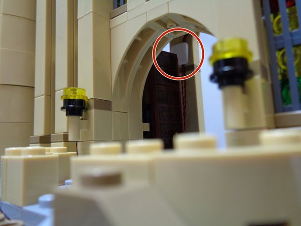
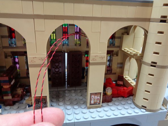
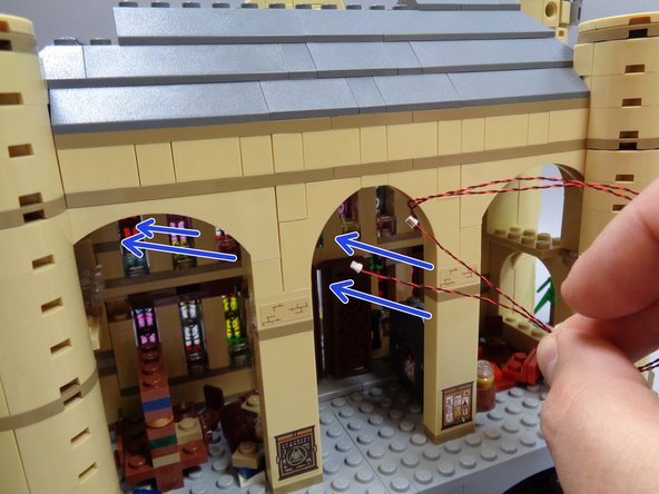
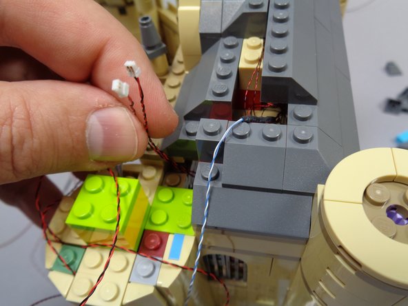

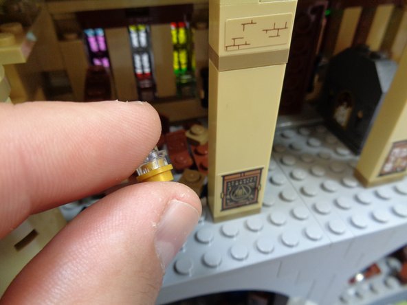
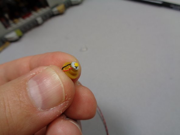
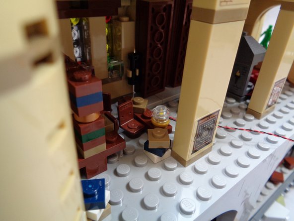

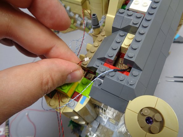
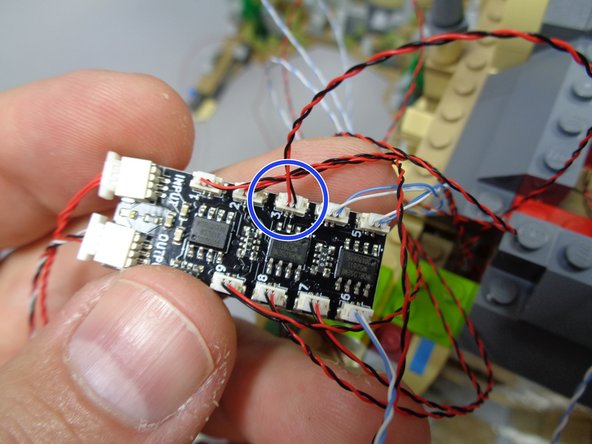
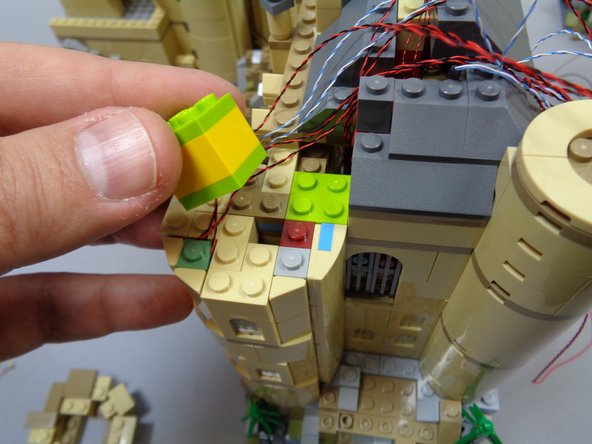

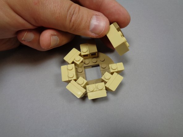
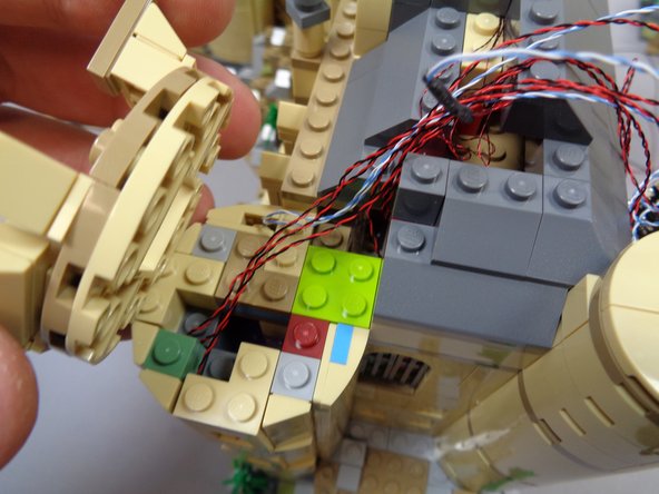
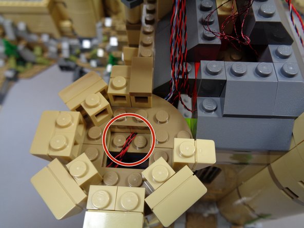
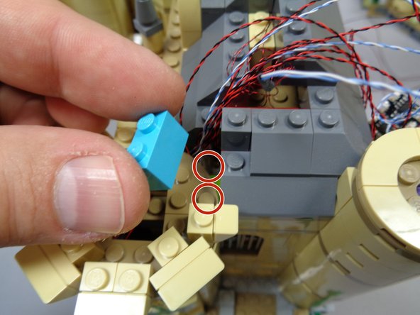
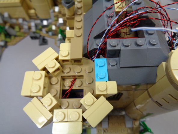
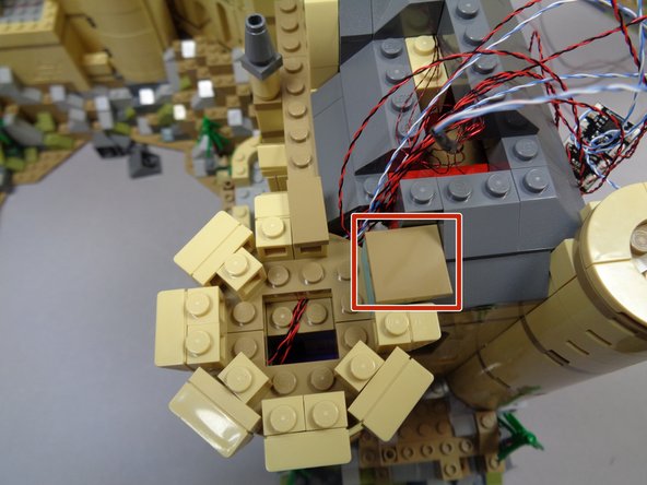

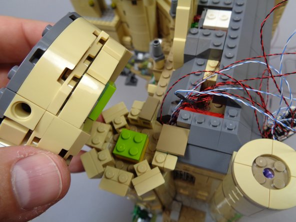
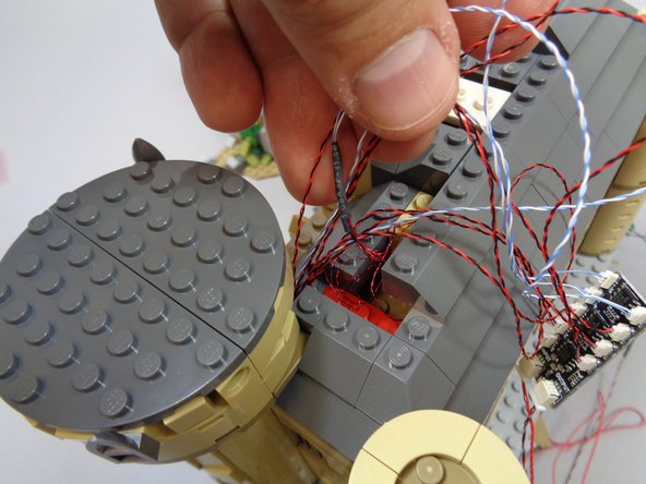
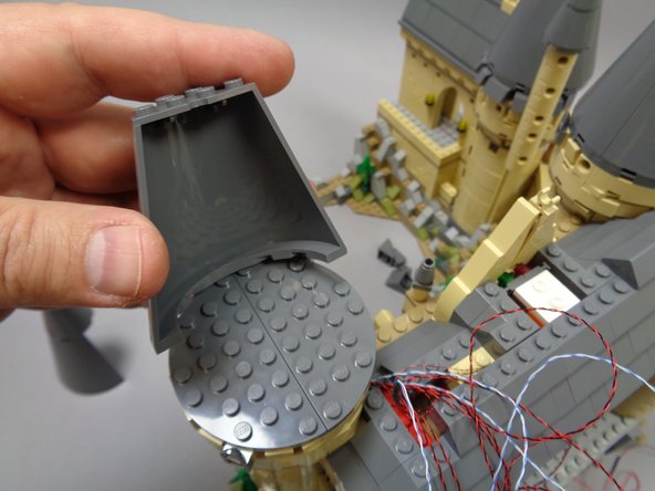

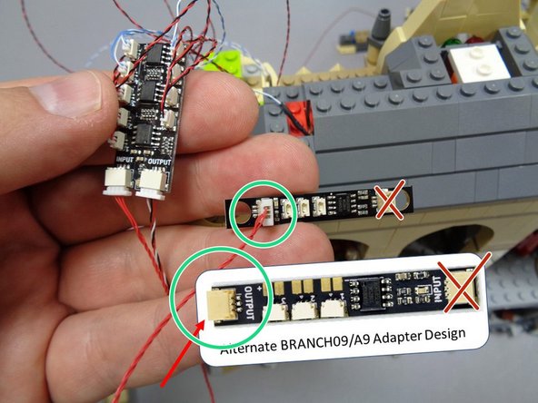
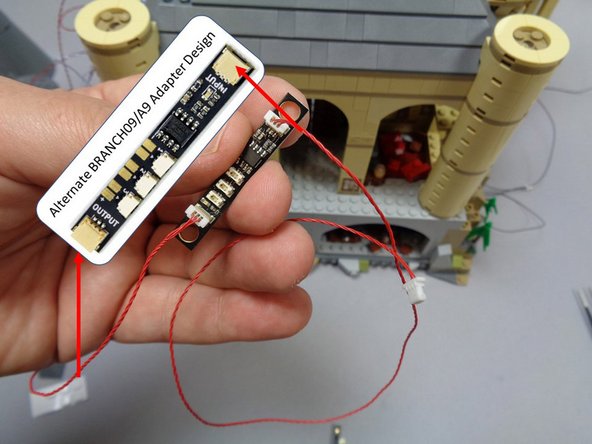
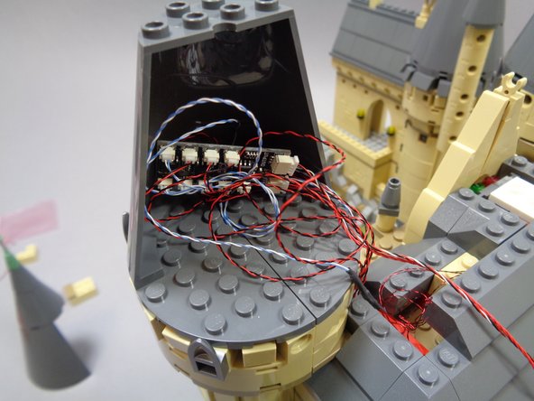
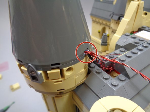

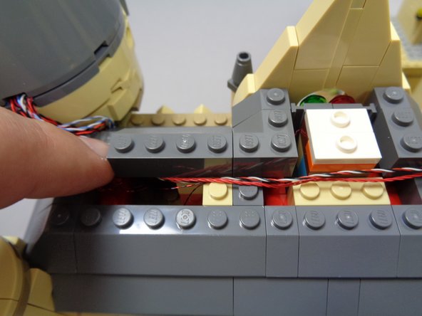
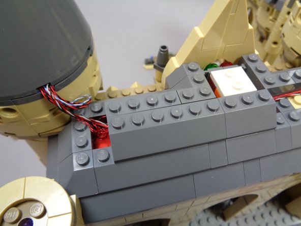
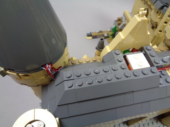
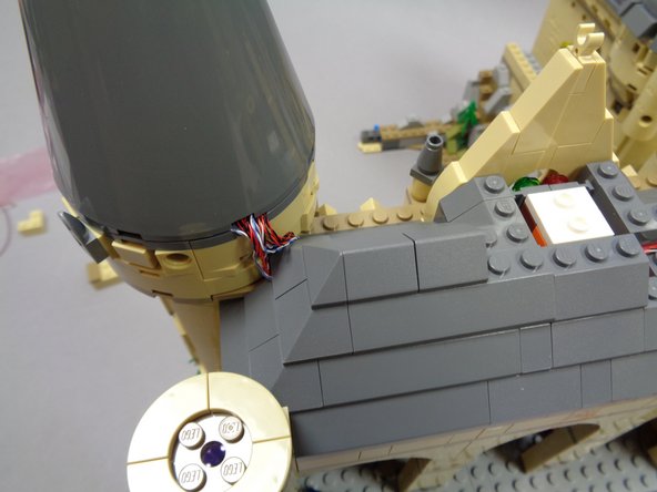
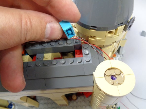
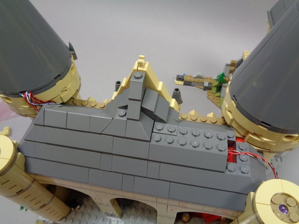
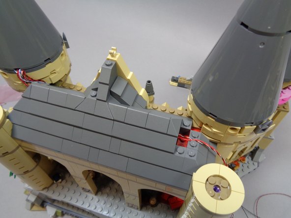

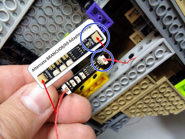

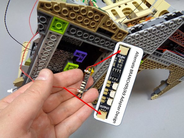
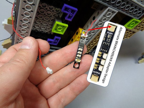
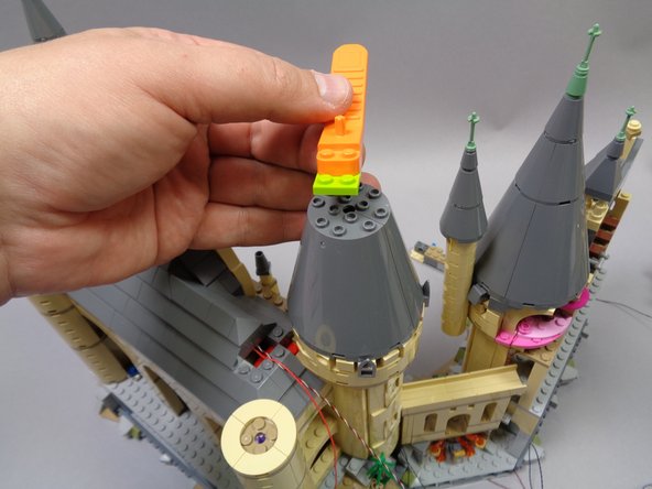
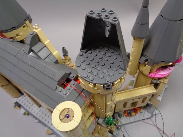


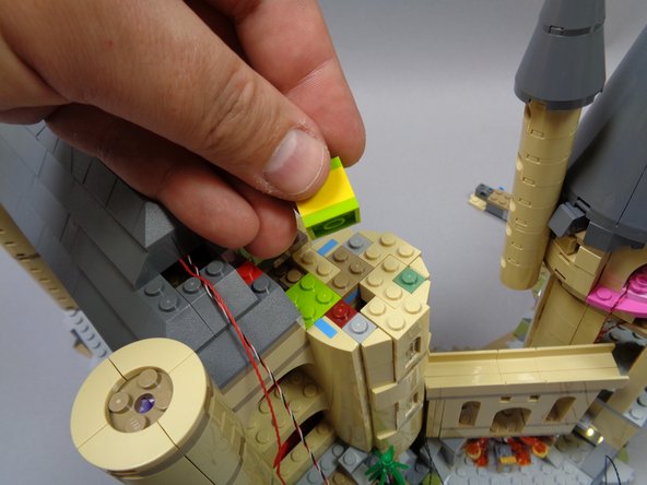
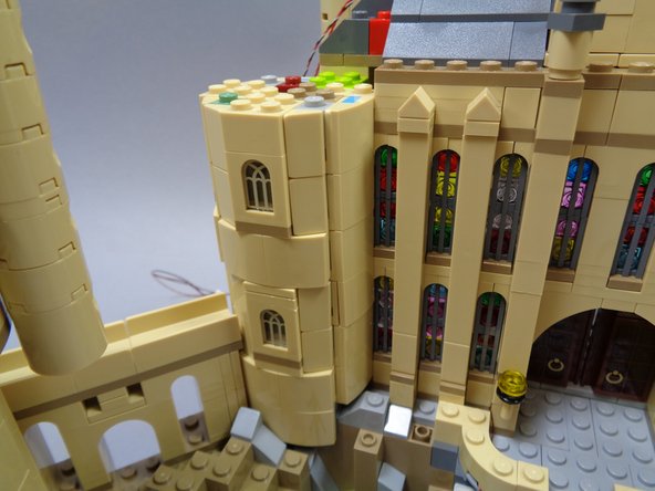
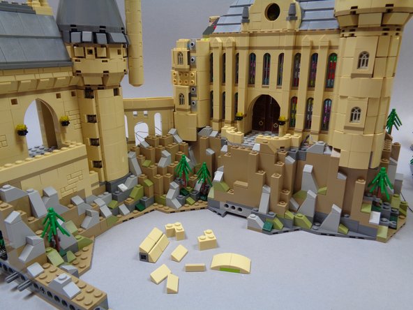

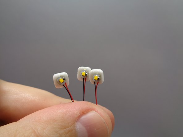
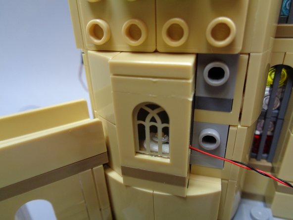
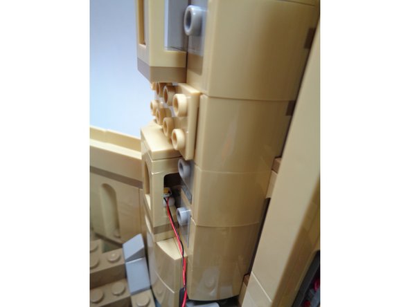
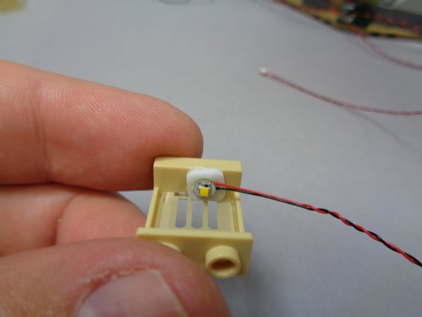

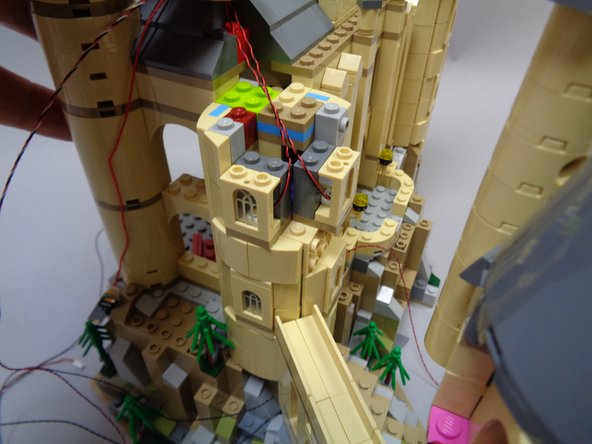
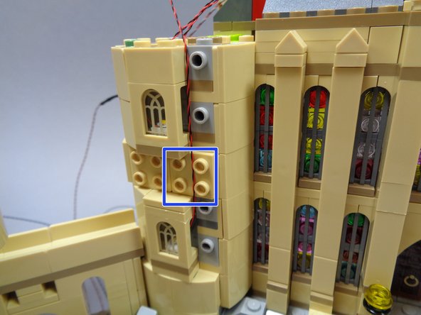
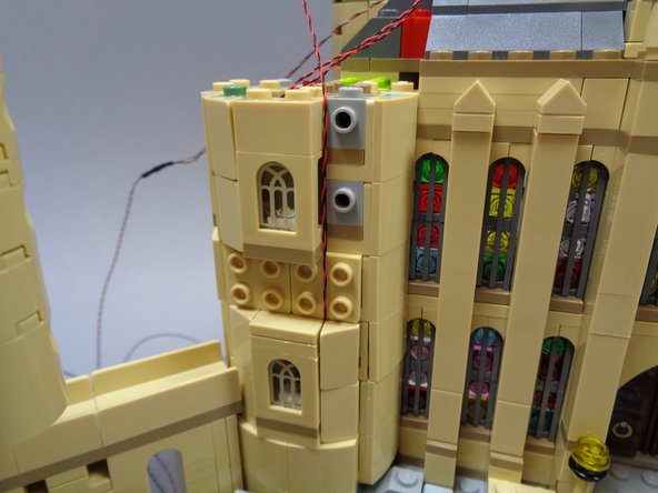

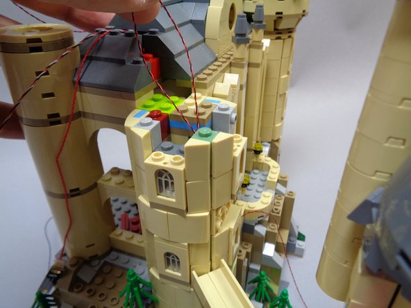
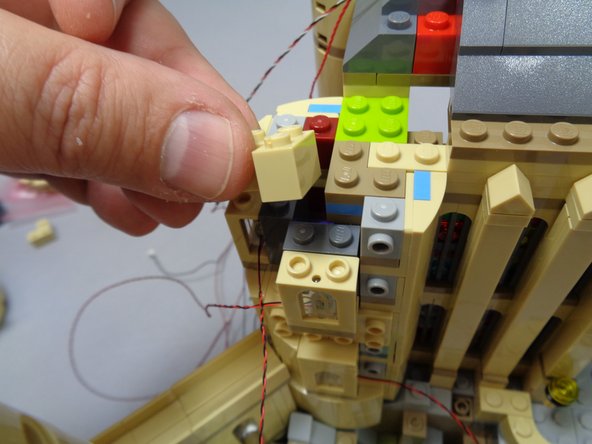
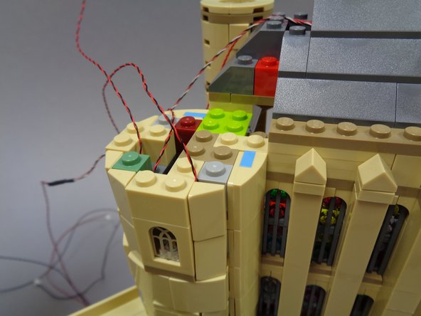
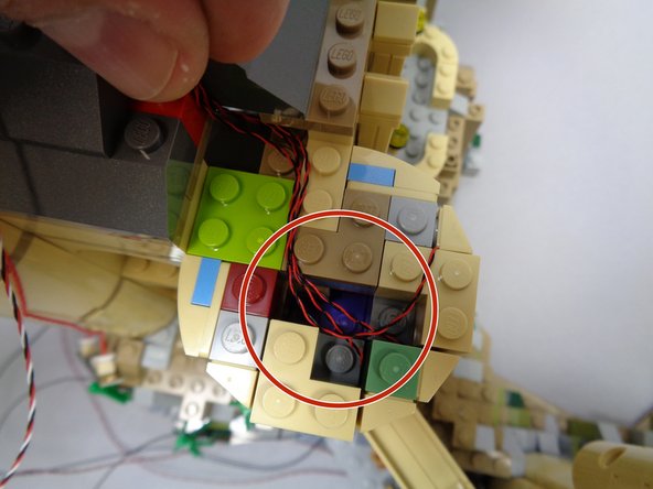
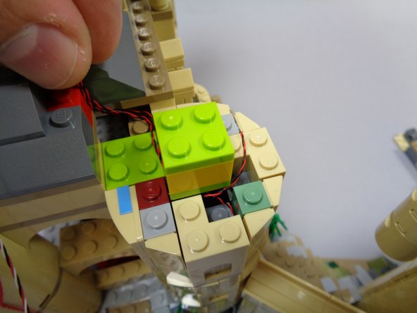


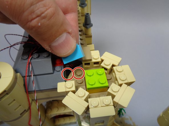
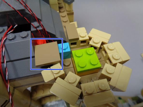
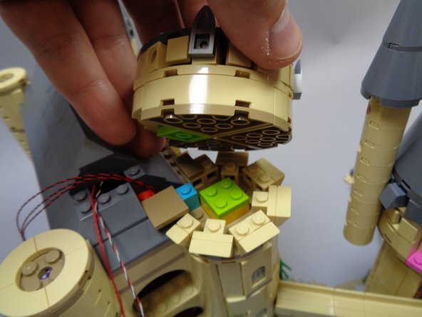
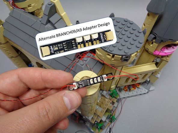
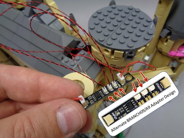
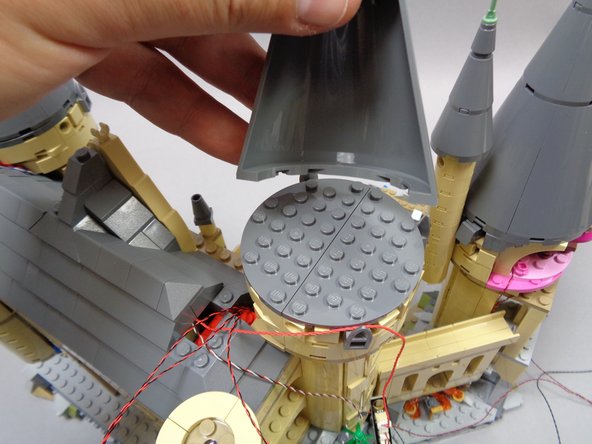
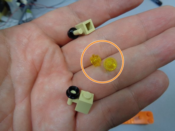

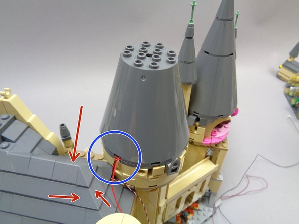

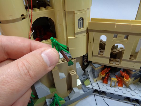
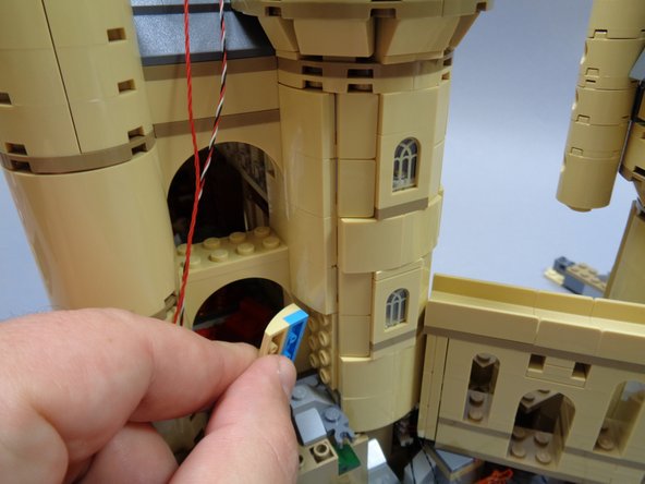
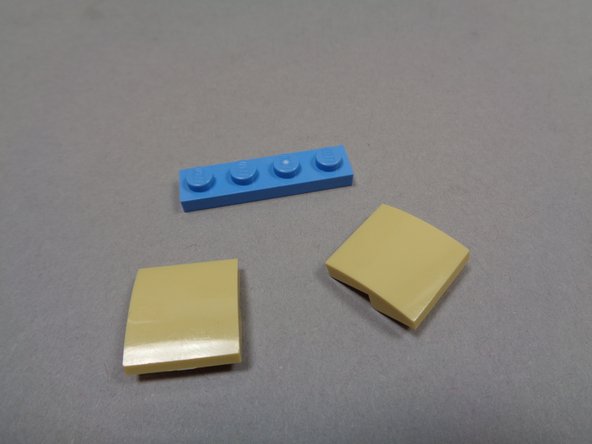
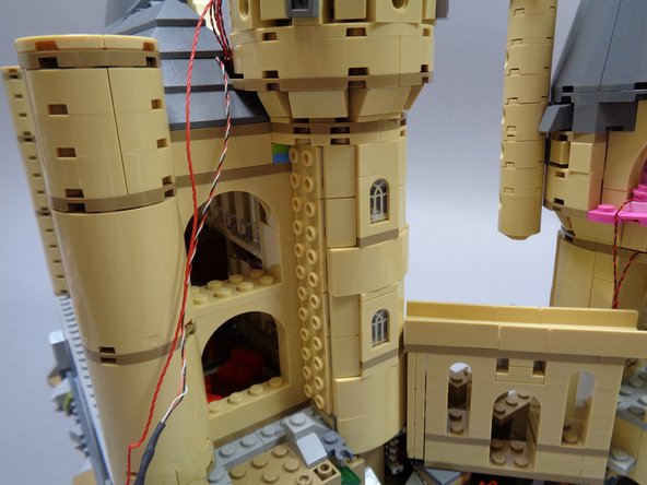
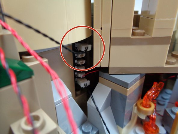
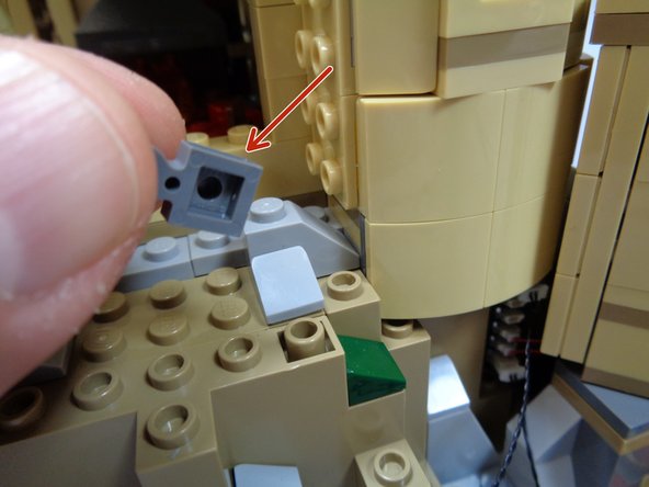
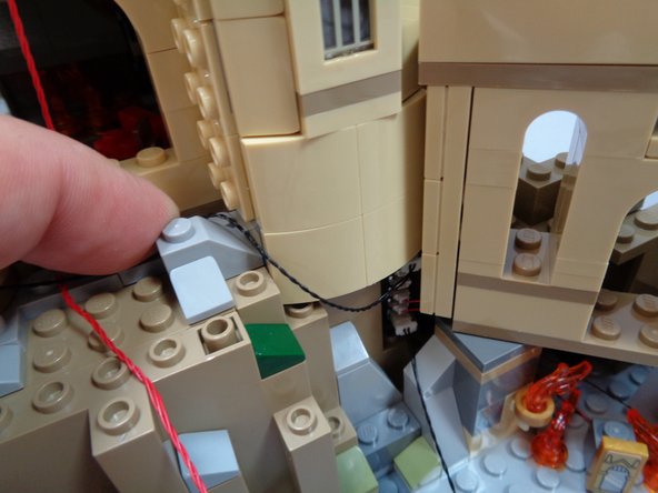
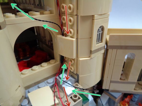
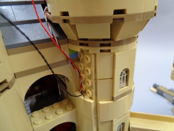
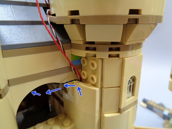

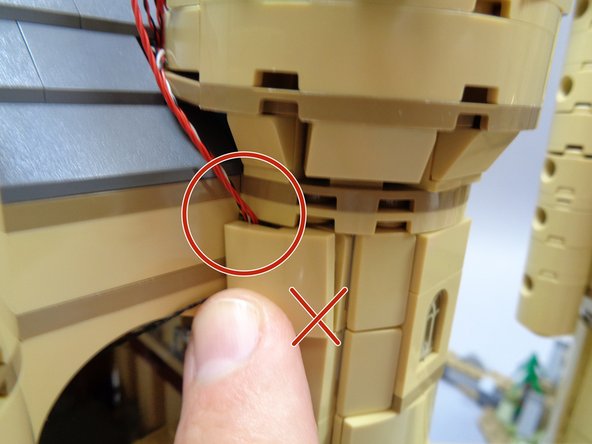

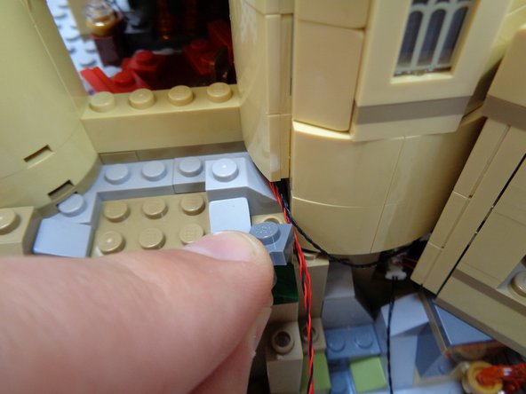
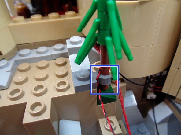
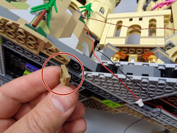

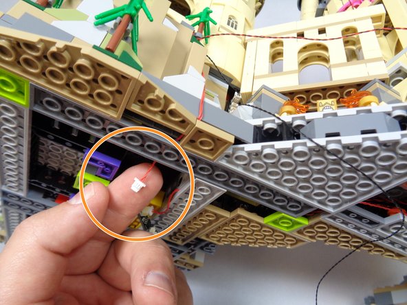

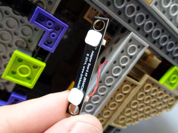
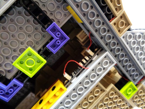
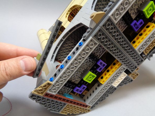
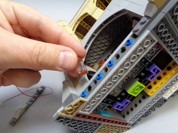


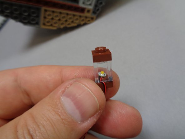
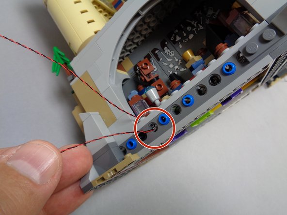
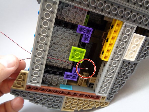

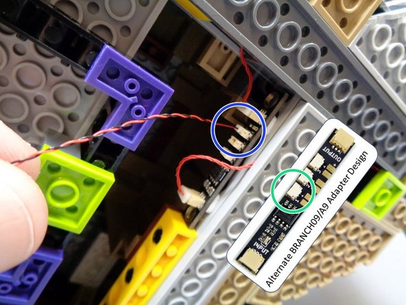
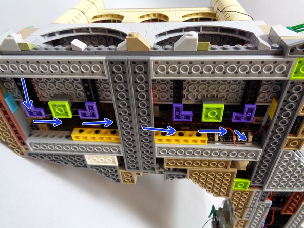
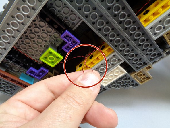
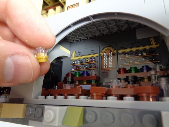
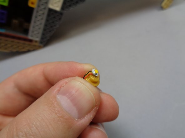
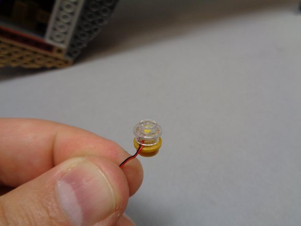
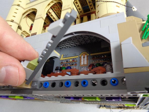


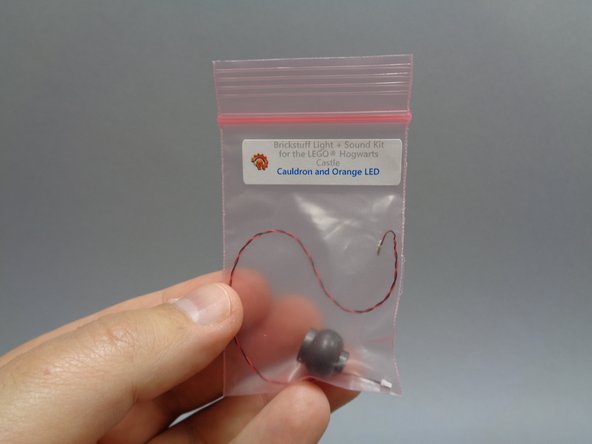

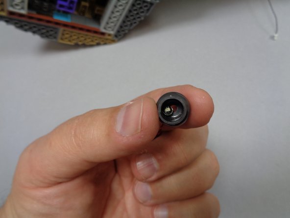
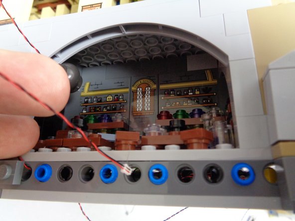
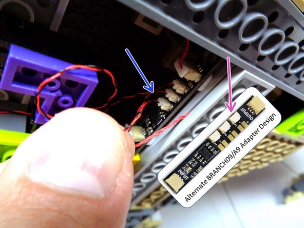
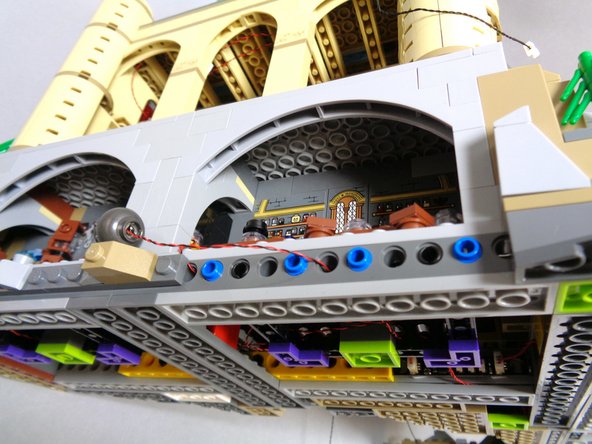
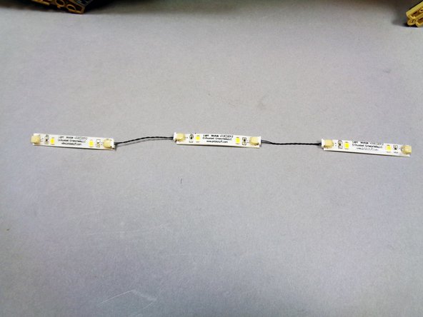
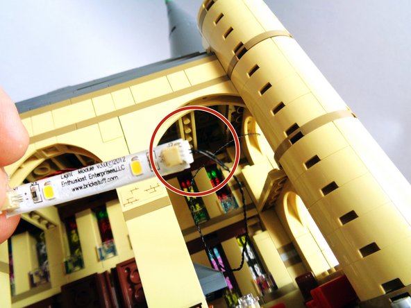

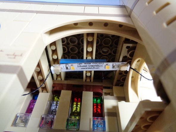
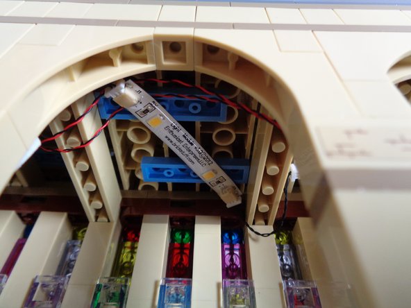

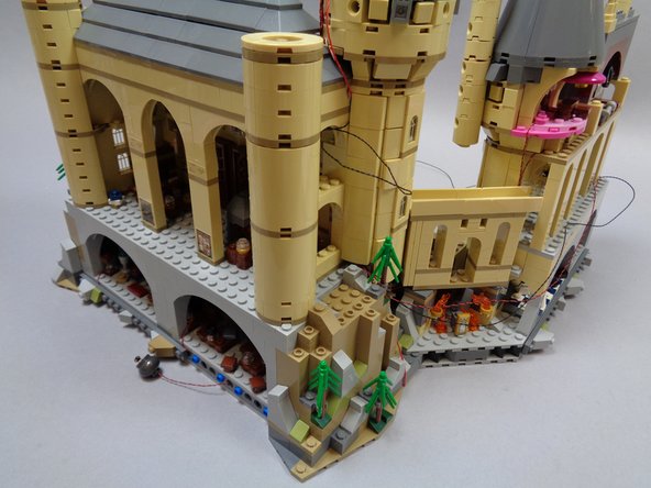
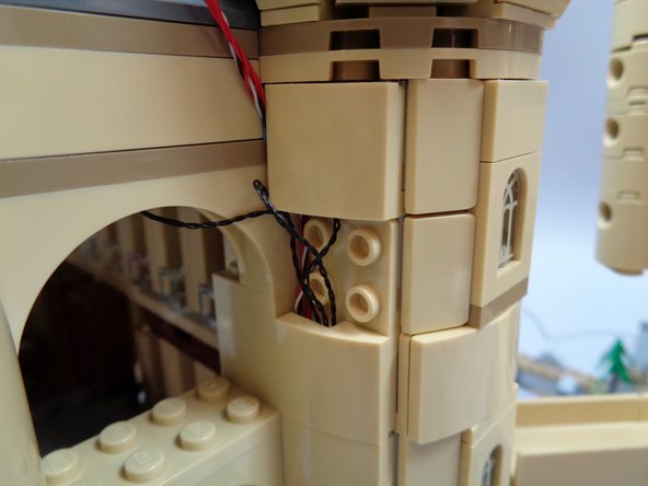
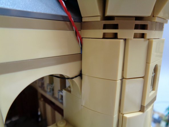
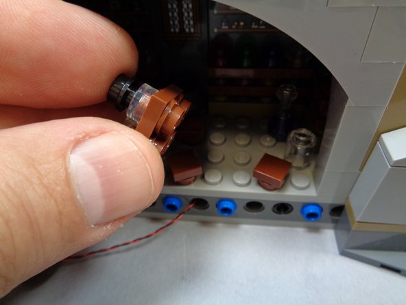


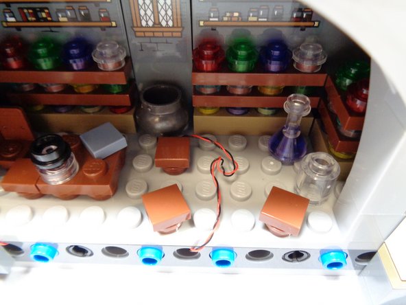


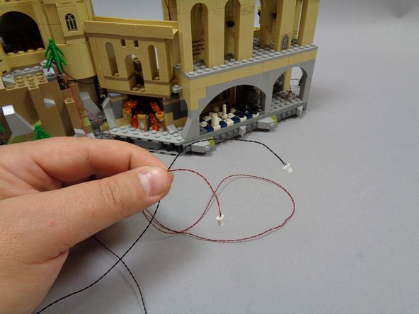
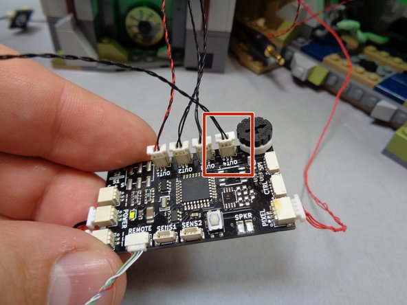
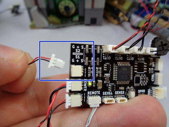
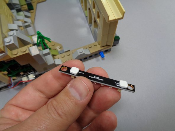
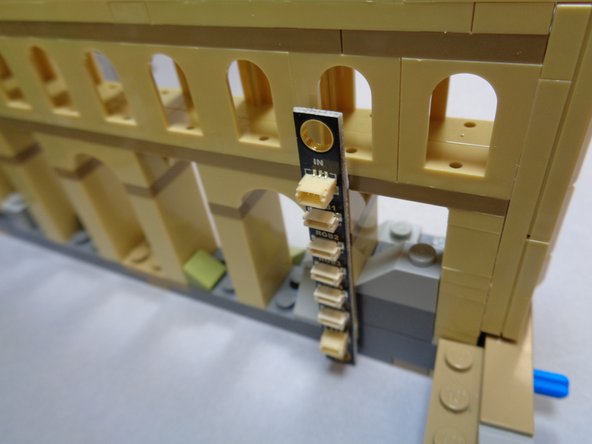

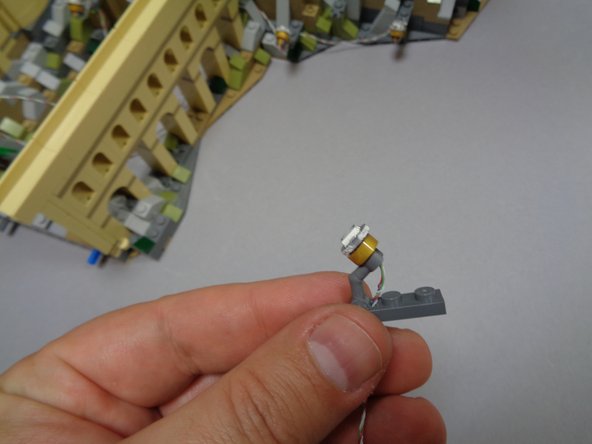

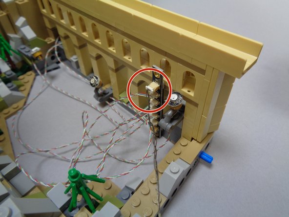

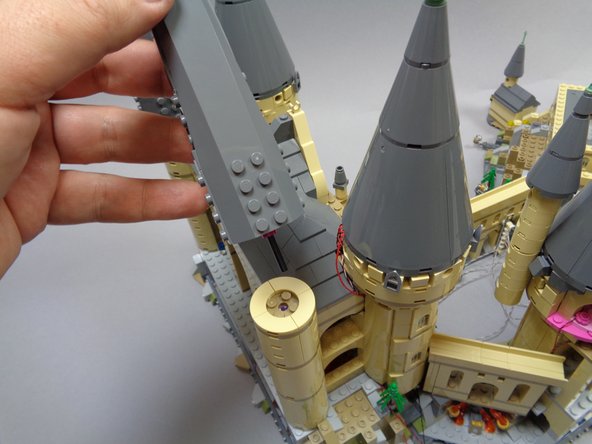
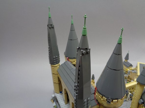

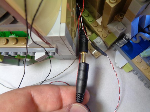

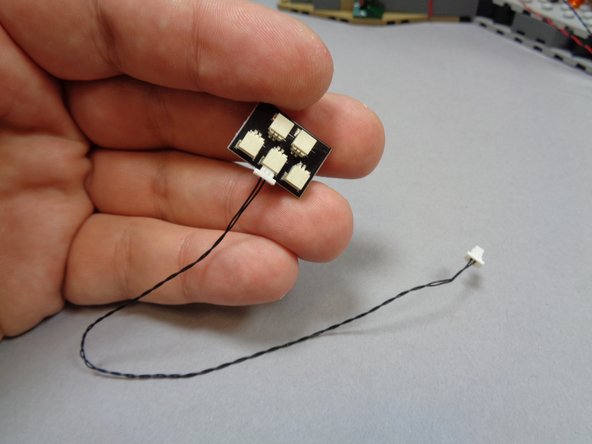
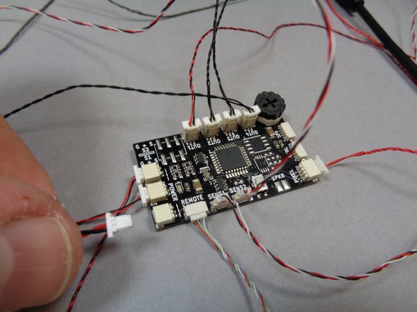
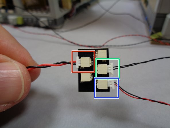
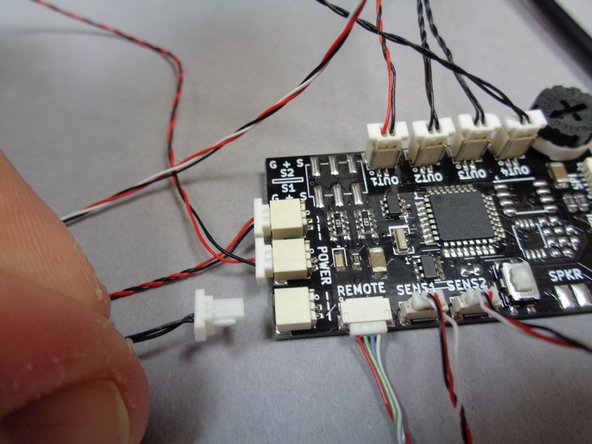
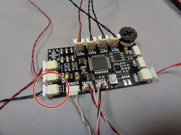
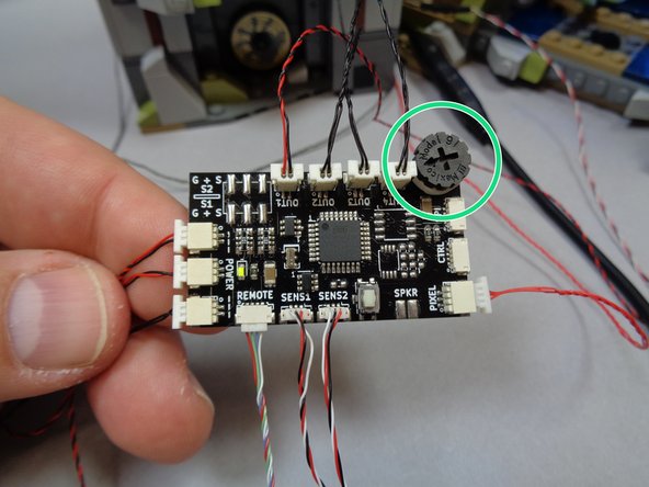


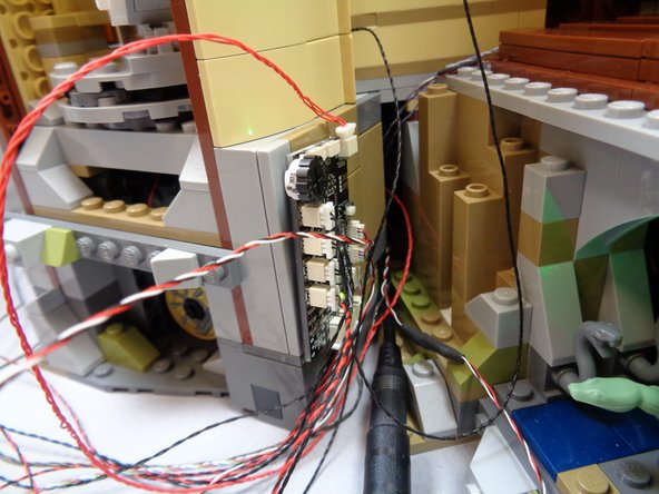

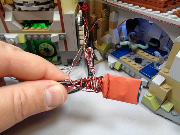
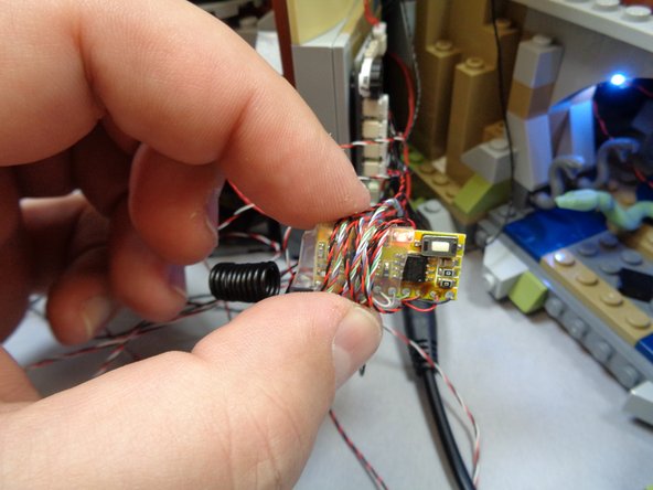
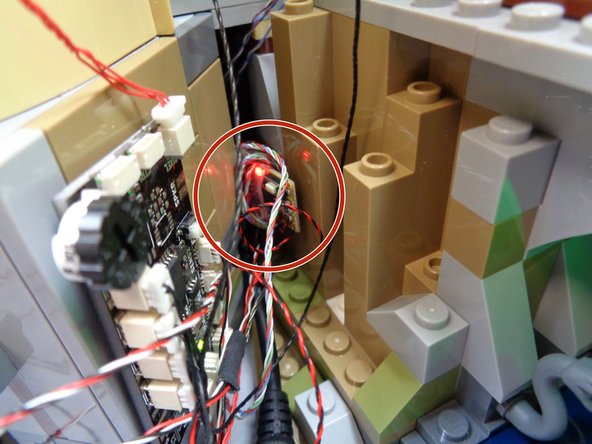
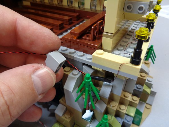
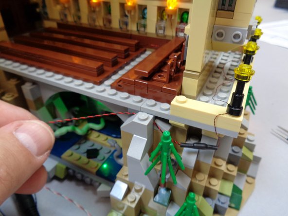

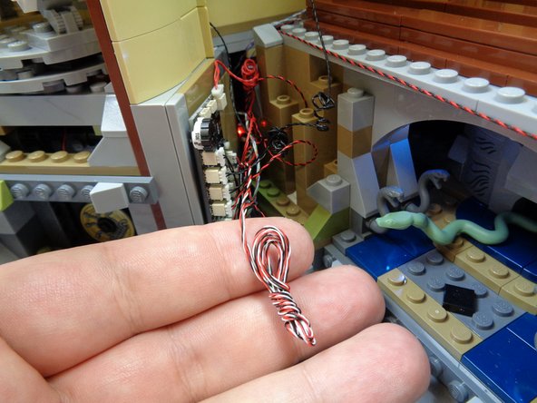
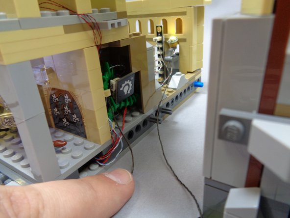
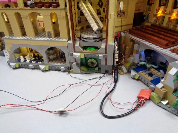

Cancel: I did not complete this guide.
3 other people completed this guide.
Attached Documents
