
Introduction
This document explains how to install and set up the Brickstuff lighting kit for the LEGO Bugatti Chiron.
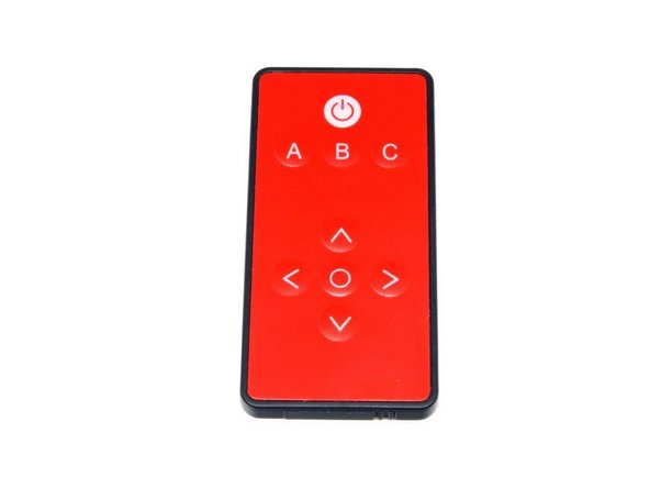
Note that these instructions are for the version of the kit that includes a red infrared remote. If your kit has a white remote, you will need to follow a different set of instructions, available here.
This guide also includes installation instructions for our add-on LED spoiler-- check the last few steps for this.
Tools
Parts
No parts specified.
-
-
Please note, these instructions are for the version of the kit that includes a red infrared remote as shown int he first photo. If your kit includes a white remote instead, you will need to follow a different set of instructions, available here.
-
First, assemble your LEGO® set. These instructions are written assuming you have already assembled your set.
-
While you will only be doing minimal disassembly of your set during installation, installation will go much more smoothly if you have a pair of tweezers to help in routing the wires through Technic holes and throughout the model. We sell our own tweezers on our website, or you can use any standard pair you might have at home.
-
-
-
The core lighting kit contains four bags of parts, plus one USB power cable.
-
Before beginning, please consult the instruction sheet that was included with your kit-- this sheet lists the parts in each bag. Please take a few minutes to make sure all parts are present in your kit.
-
You will be using Bag 1 (labeled "Core Parts") and Bag 2 (labeled "Headlight Assembly") first.
-
-
-
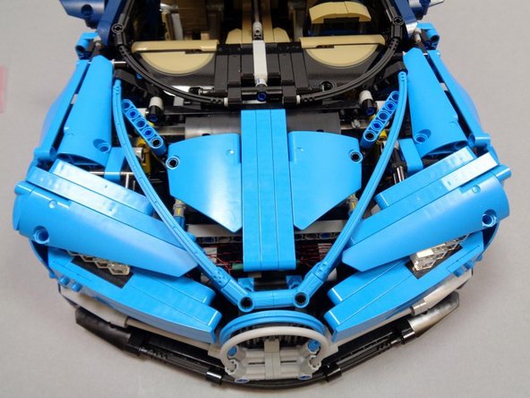
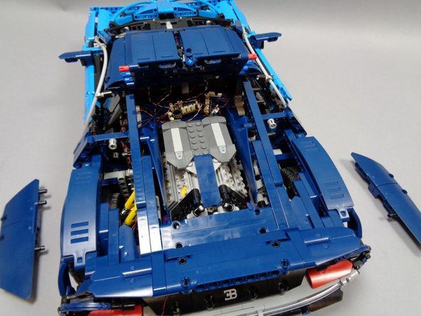
Working from the front of your Bugatti, remove the large Technic fins covering the headlights, and also remove the two headlight assemblies.
-
You will not need the white headlight assemblies, since your lighting kit includes a replacement set.
-
-
-
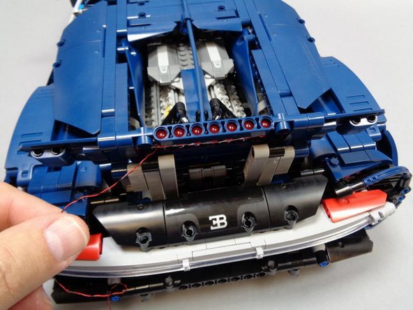
Open Bag 2 (labeled "Headlight Assembly") and carefully remove the pre-assembled headlight pair from the bag.
-
The headlight assembly is very fragile. Do not pull on any wires, as doing so may damage the LEDs inside the assembly.
-
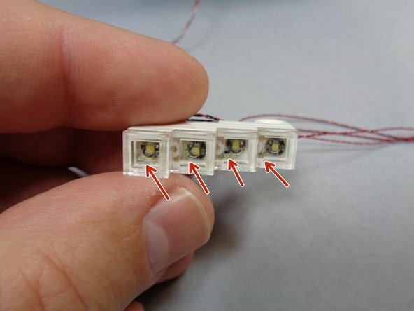
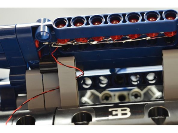
As shown in the second photo, each section of the headlight assembly has large LEDs (with black circular backgrounds) but also smaller LEDs in the corners of each panel (see red arrows in photo 2).
-
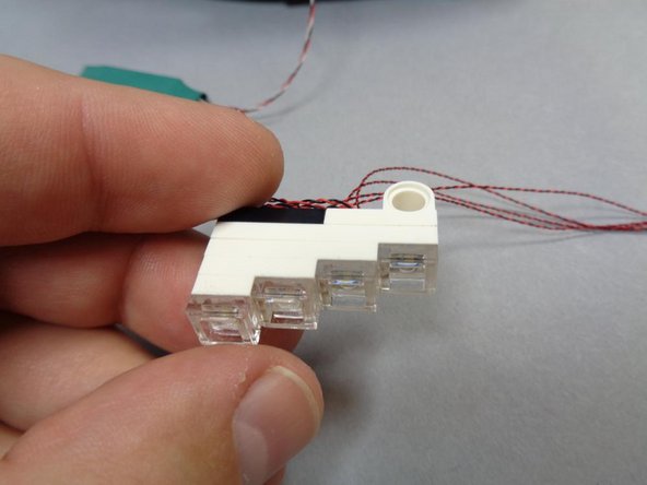
In order for the headlights to function correctly, it is important to mount them on the car frame with the smaller LEDs facing the BOTTOM of the assembly.
-
Each half of the headlight assembly has a top and bottom. The bottom of each is indicated by the small LEDs in the lower corner.
-
-
-
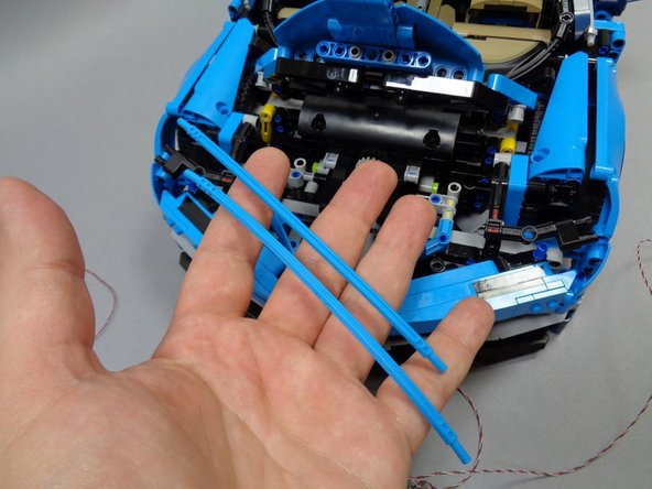
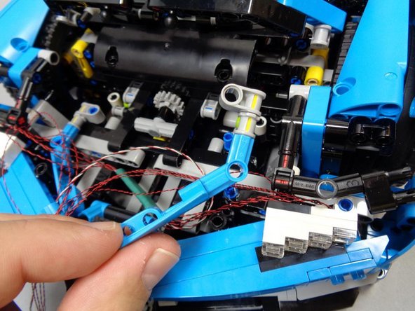
Remove the two blue Technic bars to open up more space under the hood area. This will make installing the headlights easier.
-
Carefully attach the new headlight assembly as shown in the second photo. Make sure the circuit board with the green covering is located in the center of the car.
-
Remember, the headlights must be mounted so each half has its smaller LEDs (in the corner of each panel) facing the bottom of the car.
-
-
-
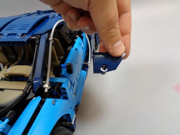
After the headlights have been attached, carefully remove the brackets (on both sides of the car) as shown in the first photo.
-
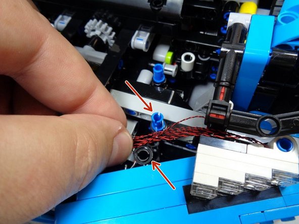
As shown in the second photo, carefully route the wires between the lower blue pin and the black beam (two red arrows in the second photo).
-
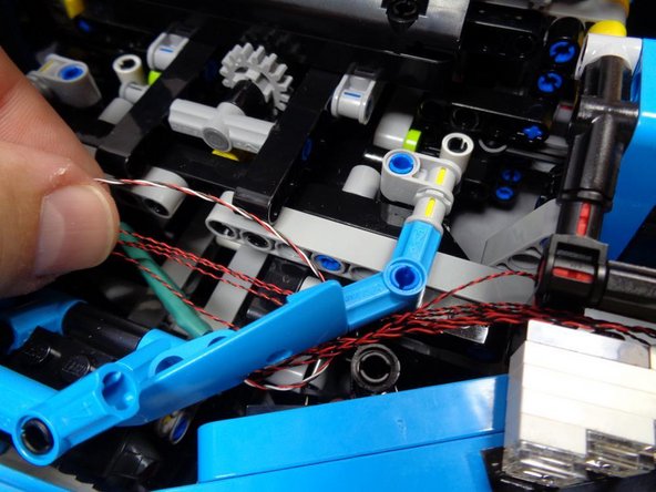
As shown in the third photo, replace the bracket you removed in the beginning of this step.
-
Make sure the wires are routed BETWEEN the pins, and that no wires are pinched by any pins.
-
Repeat for the other headlight.
-
-
-
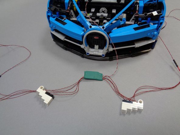
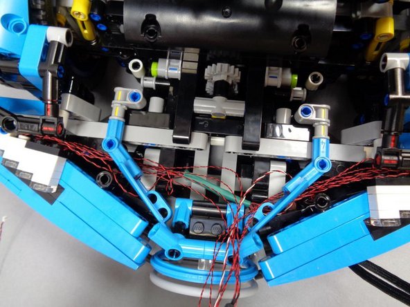
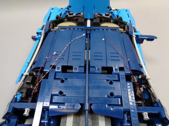
After mounting both headlights and routing the wires, check the three photos in this step to make sure you have the wires routed correctly.
-
The circuit board with the green covering should sit in the center of the area behind the front grille, as shown in the photos.
-
-
-
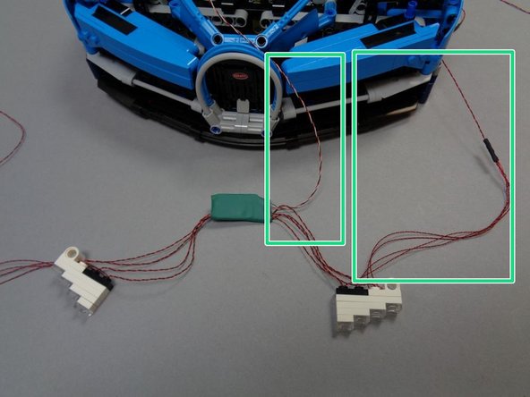
As shown in the first photo (green rectangles), your headlight assembly should have two wires coming out one end of the green circuit board assembly.
-
In this step, you will route the LEFT headlight wire and the THREE-WIRE cable (with red/black/white wires).
-
As shown in the second photo, remove the rear-view mirror on the RIGHT side of the vehicle. This will make it easier to turn the car on its side to route the wires.
-
Carefully turn the car on its side and place on a flat surface.
-
As shown in the third photo, carefully pull the LEFT headlight wire and the THREE-WIRE cable down to the underframe of the car.
-
Do not pull hard on any wires, or you may damage the headlight LEDs.
-
-
-
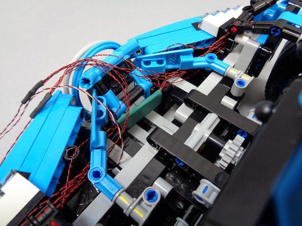
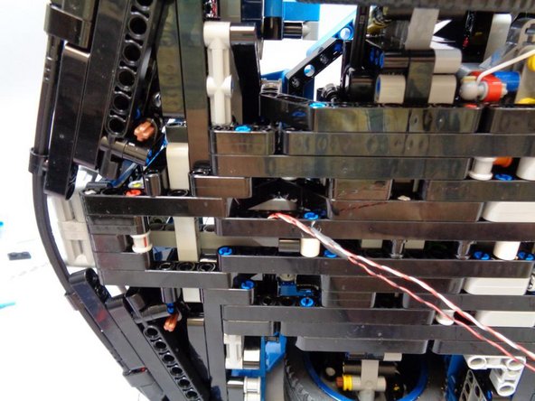
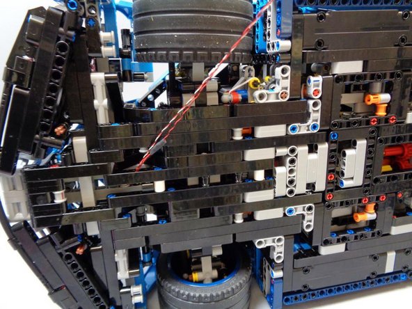
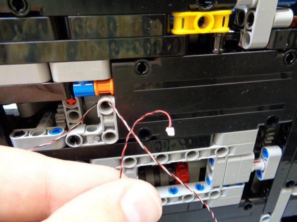
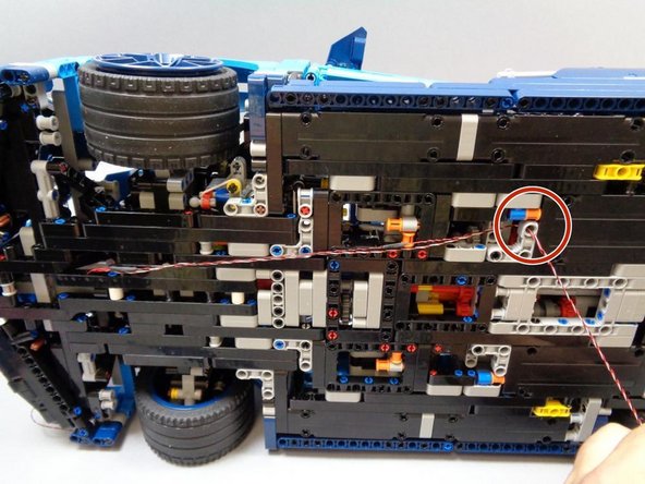
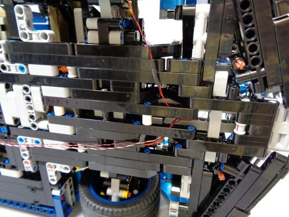
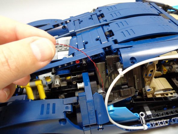
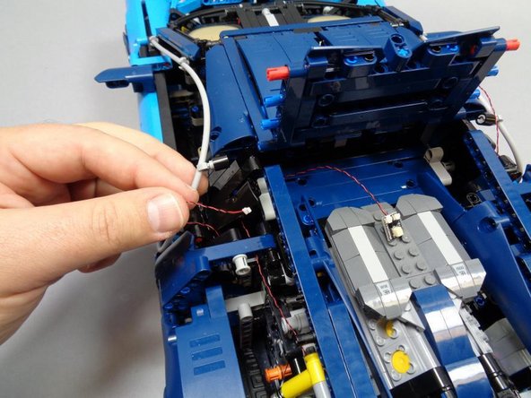
In this step, as shown in the three photos, you will continue routing the two wires toward the back of the car.
-
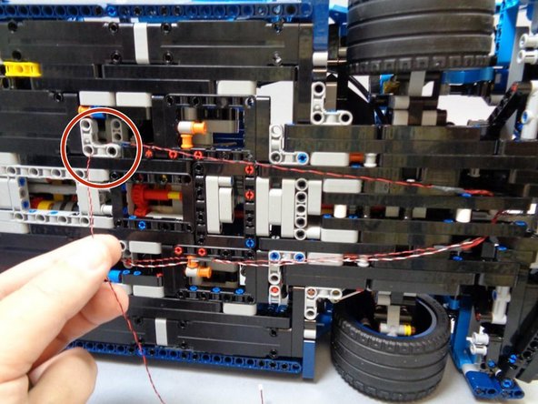
As shown in the second photo, bending the wires a little makes it easier to route them through the hole in the Technic bracket shown by the red circle in the third photo.
-
It is important that both wires are routed as shown in the photo, including up and through the Technic hole under the driver's seat. This is necessary to keep the wires from dragging on the ground.
-
-
-
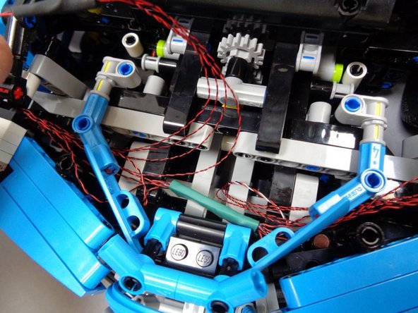
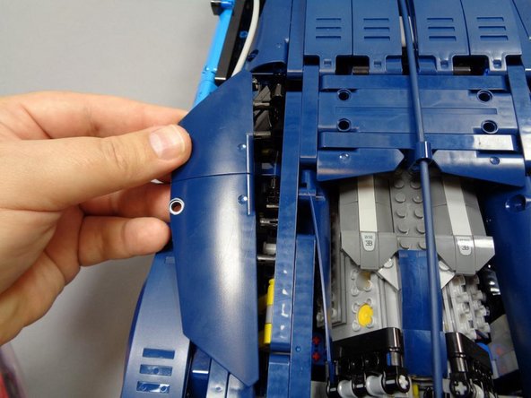
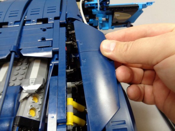
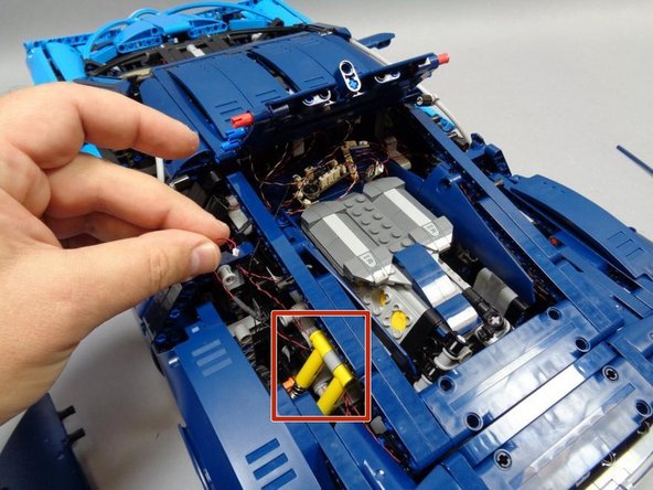
As shown in the first photo, carefully remove the Technic panels on the left rear of the Bugatti.
-
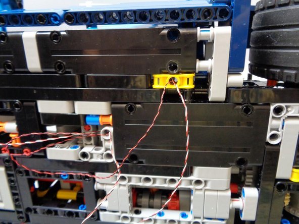
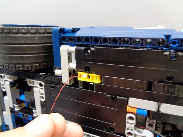
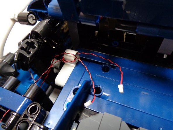
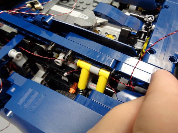
Back under the car, carefully thread BOTH cables through the hole in the YELLOW Technic bracket and up toward the top of the car as shown in the second photo.
-
As shown in the third photo, carefully pull both cables up toward the top of the car.
-
This completes the initial routing of the first set of cables. Leave both cables hanging free for now.
-
-
-
As shown in the first photo, re-attach the blue Technic hose you removed earlier.
-
As shown in the second photo, remove the LEFT rear-view mirror-- this will make it easier to turn the car on its side in the following step.
-
You can re-attach the RIGHT rear-view mirror you removed in Step 8.
-
As shown in the third photo, take the wire coming from the RIGHT turn signal and gently push it down toward the underside of the car.
-
-
-
Gently turn your car on its side and place on a flat surface.
-
As shown in the second photo, route the wire toward the rear of the car, looping it up and through the pin hole in the Technic bracket as shown by the red circle.
-
As shown in the third photo, route the wire up and through the hole in the yellow Technic bracket, toward the top of the car.
-
-
-
As shown in the first photo, remove the right Technic panels at the rear of the vehicle.
-
As shown in the second photo, gently pull the wire that you routed in the last step up toward the top of the vehicle.
-
As shown in the third photo, you should have successfully routed three wires:
-
The LEFT front turn signal wire.
-
The THREE-WIRE headlight control cable.
-
The RIGHT front turn signal wire.
-
You can now re-attach the LEFT rear-view mirror that you removed in Step 11.
-
-
-
As shown in the first photo, re-attach the blue Technic hose you removed in Step 5.
-
As shown in the second photo, re-attach the left and right blue Technic panels (headlight covers) that you removed in Step 3.
-
As shown in the third photo, you should now be able to close the hood, and all wires should be concealed inside the hood.
-
-
-
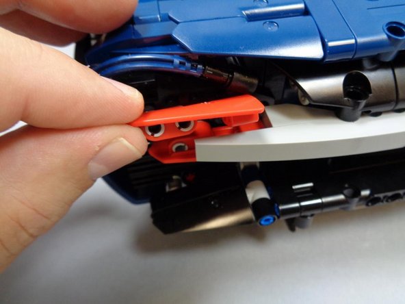
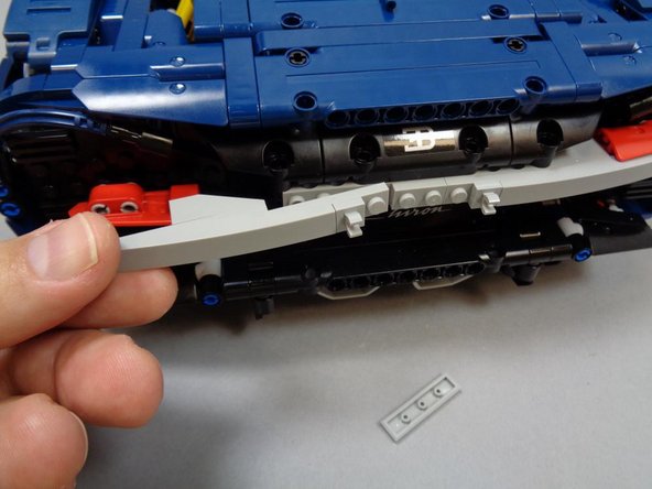
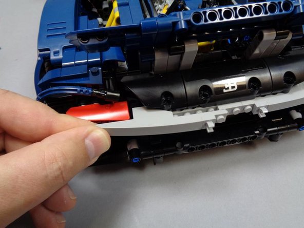
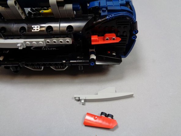
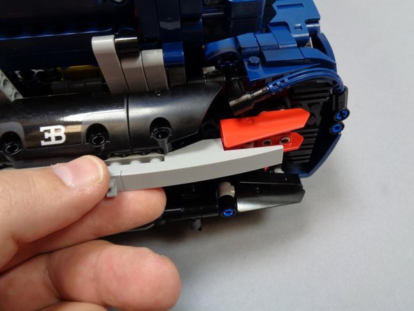
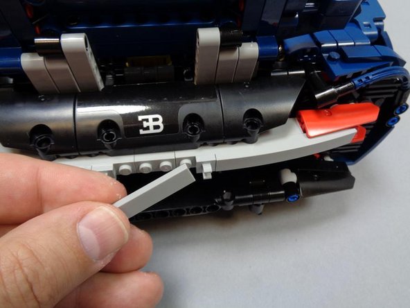
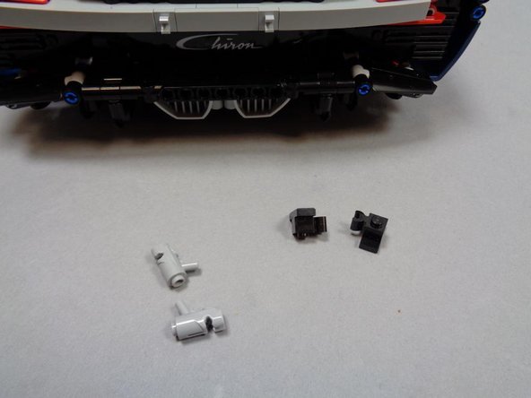
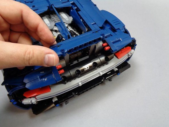
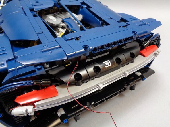
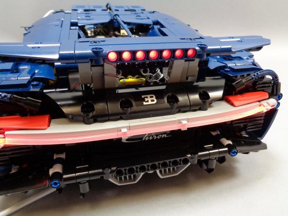
As shown in the first photo, remove the two light bluish gray "blaster" parts and the red tail light tube.
-
As shown in the second photo, remove the top left red tail light cover.
-
As shown in the third photo, remove the left half of the light bluish gray tail light mount.
-
-
-
Open Bag 1 (labeled "Core Parts") and carefully remove the parts inside. Lay on a flat surface where you won't lose any parts.
-
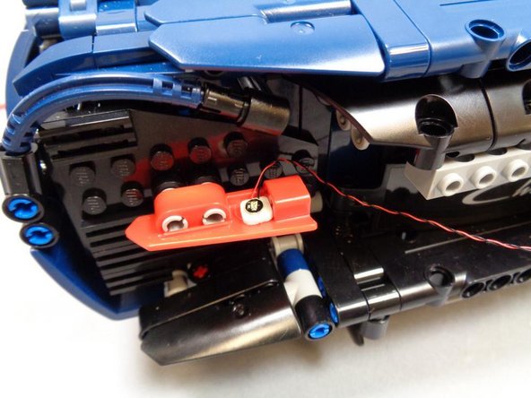
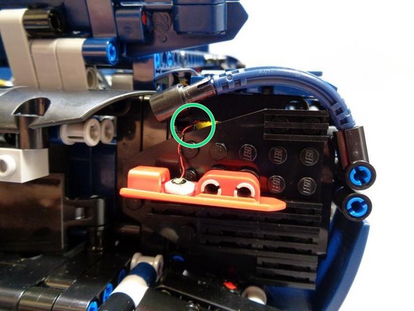
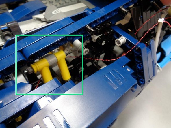
As shown in the first photo, use on the sticky squares included with your kit to mount one of the red Pico LEDs from Bag 1 to the LOWER turn signal cover as shown.
-
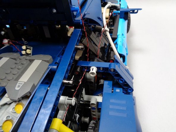
As shown in the second photo, route the left rear turn signal wire through the small hole above the black rear plate (red circle)
-
As shown in the third photo, make sure the wires run BEHIND the yellow shock absorbers (green rectangle) and through the hole in the blue beam (green arrow).
-
-
-
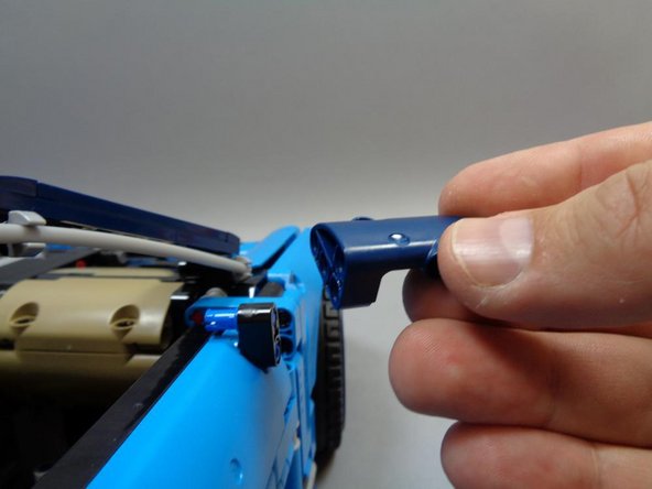
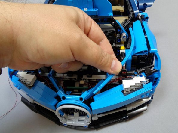
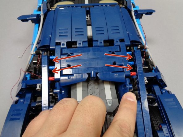
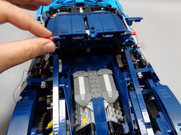
Remove the long blue tube from the center roof as shown in the first photo.
-
As shown in the second photo, disconnect the left and right Technic beams holding the rear roof.
-
With the two Technic beams disconnected from the roof, it should tilt up and open as shown in the third photo.
-
-
-
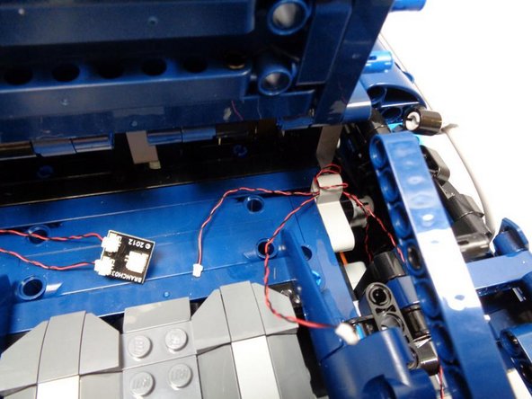
As shown in the first photo, route the wires from the front and rear left turn signals toward the center area under the roof.
-
As shown in the second photo, you can wind the front and rear turn signal wires around the Technic bracket if you have excess wire length.
-
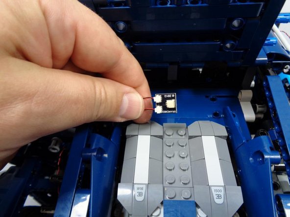
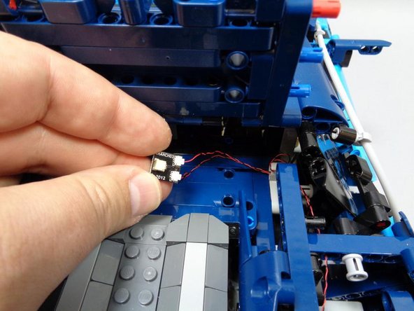
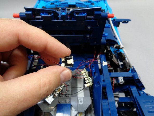
As shown in the third photo, take one of the BRANCH03 adapter boards from Bag 1 and connect both the front and rear left turn signal wires to the small connectors on the BRANCH03 board.
-
The wires will only insert one way-- do not force. You can use your fingernail to press the connectors into place-- you should feel a little "click" when the plugs are fully inserted.
-
-
-
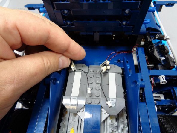
As shown in the two photos for this step, re-assemble the left turn signal assembly.
-
-
-
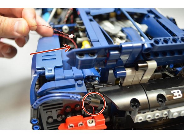
Dissemble the top half of the right rear turn signal and tail light bracket as shown in the first photo.
-
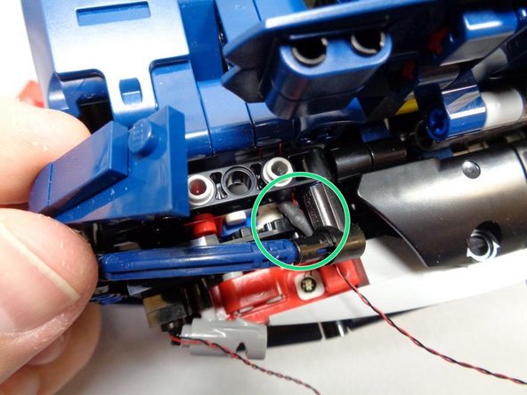
Using one of the sticky squares included with your kit, mount the second red Pico LED from Bag 1 to the lower half of the red rear turn signal panel.
-
Route the Pico LED cable through the small hole above the turn signal assembly as shown by the green circle in the second photo.
-
As shown in the third photo, route the wire up toward the front of the car. As shown by the green rectangle, make sure the Pico LED cable passes behind the yellow shock absorbers.
-
-
-
As shown in the first photo, continue routing the wire from the previous step through the hole in the blue Technic beam.
-
As shown in the second photo, route the wires from the front and rear turn signals through the gray Technic bracket. If you have extra cable, wrap both wires around the bracket to take up the slack.
-
As shown in the third photo, use another BRANCH03 adapter board from Bag 1 to connect both the front and rear right turn signal wires.
-
Connect both cables to the small plugs on the BRANCH03 adapter board.
-
-
-
Take two 1.5" black connecting cables from Bag 1, and connect them to the large plugs on both BRANCH03 adapter boards as shown in the first photo.
-
The plugs will fit in only way-- do not force. Make sure to press the plugs fully into their sockets.
-
If you ever need to remove a large plug from its socket, always use the white tabs and your fingers to remove. Never pull from the wire, or you will break the plug. Broken plugs cannot be repaired.
-
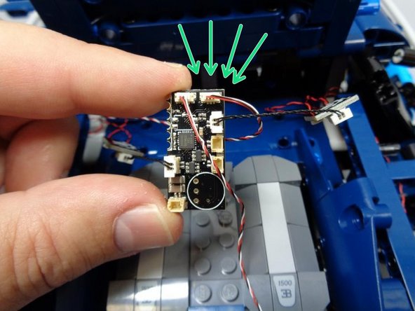
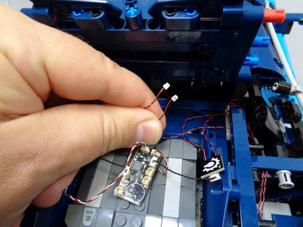
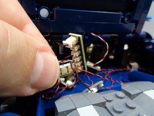
Remove the main controller board from Bag 1. It should have the black infrared receiver and wire already connected to the SENS1 plug on the board.
-
As shown in the second and third photos, carefully connect the 1.5" black cables to the main controller board. Note which specific connectors the plugs connect to (red arrows in the third photo). In order for the lights to operate correctly, the wires must be connected exactly as shown.
-
-
-
In this step, you will connect the 3-wire headlight cable to the main controller board.
-
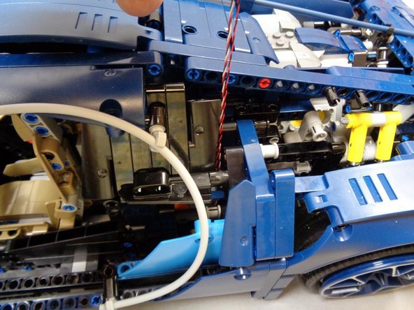
As shown in the first two photos, route the 3-wire headlight control cable into the same area as the main controller board.
-
As shown by the green arrows in the third photo, connect the 3-wire headlight control cable to the SENS2 plug in the upper right corner of the main controller board.
-
The plug will fit only one way-- do not force. Press the plug in with your fingernail-- you will feel a "click" when the plug is fully inserted.
-
-
-
As shown in the three photos for this step, re-assemble the rear right turn signal and tail light mount.
-
-
-
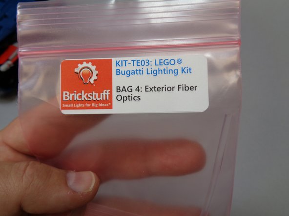
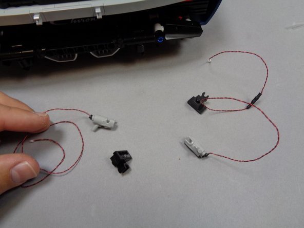
Take Bag 4 (labeled "Exterior Fiber Optics") and carefully remove the long clear fiber optic tube and two light bluish gray "blasters" with red LEDs pre-mounted.
-
Remove the two "blaster" parts that came with your LEGO® set. You will not need them any longer.
-
Carefully attach the Brickstuff "blaster" parts to the black brackets.
-
The LED wires coming out of the ends of the "blaster" assemblies are very fragile.
-
-
-
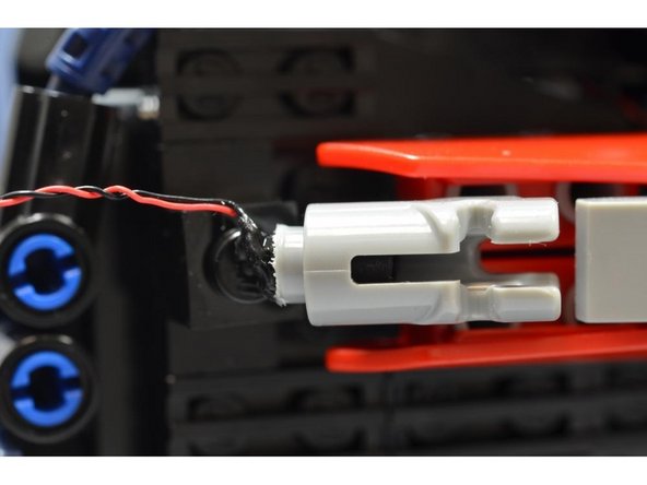
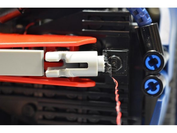
Mount both "blaster" assemblies, one on the left side and the other on the right side of the rear of the car.
-
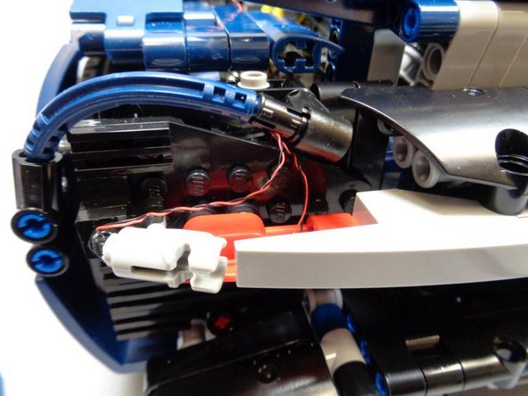
As shown in the first two photos, one "blaster" assembly will have its LED wires extending upward, and the other will have its wires extending downward.
-
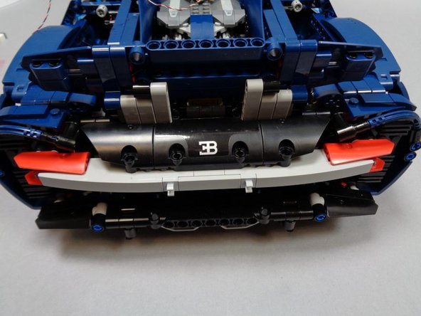
As shown in the third photo, you may need to remove some parts on top, and possibly the large black plate on the rear of the car itself, in order to route the tail light wires.
-
As shown by the green circle in the third photo, you may need to remove these parts in order to allow the black shrink-wrapped portion of the cable (which is thicker than the wire) to pass through.
-
Route the wires for both the left and rear tail lights, and re-attach any parts you removed to allow the wires through.
-
The following step has some additional tips for successfully routing the wires.
-
-
-
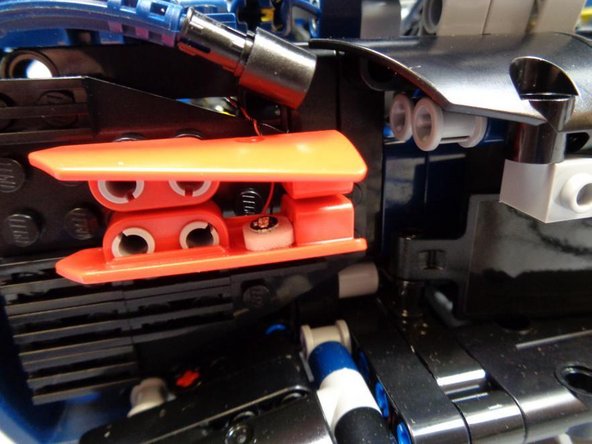
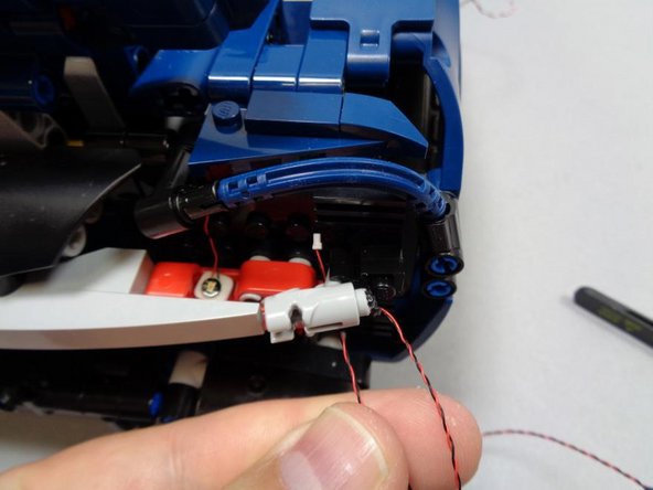
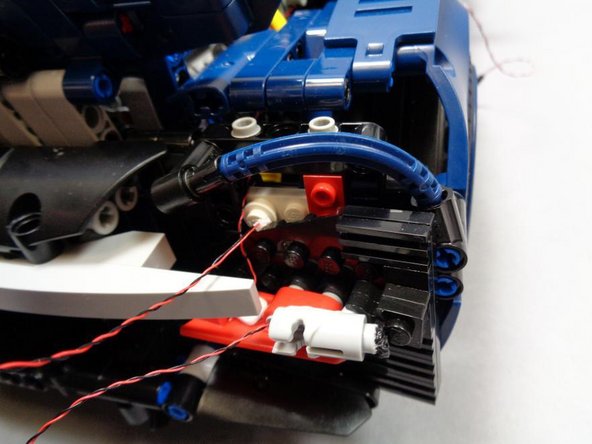
The photos in this step show some tips for routing the wires for both the left and right rear tail light "blaster" parts.
-
Note that on the side of the car with the wire extending downward from the "blaster" assembly, you will need to run the wire back up behind the "blaster" as shown in the second photo.
-
-
-
As shown in the photos for this step, route the wires for the left and right tail light LEDs behind the yellow shock absorbers like you did earlier with the turn signal wires.
-
As shown in the third photo, after routing both tail light wires, you should have both cables in the center rear of the car, close to the master control board.
-
-
-
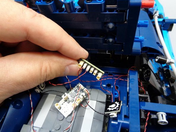
Remove the 4-port BRANCH15 adapter board from Bag 1, and also pick up another 1.5" black connecting cable from the same bag.
-
As shown in the first photo, carefully connect the two tail light plugs to any two of the small plugs on the BRANCH15 adapter board.
-
Remember, plugs will only insert one way-- do not force. Use your fingernail to press the plugs in all the way.
-
As shown in the second photo, connect the black 1.5" connecting cable to either one of the large connectors on the BRANCH15 adapter board.
-
As shown in the third photo, connect the 1.5" connecting cable to the main control board as shown. For proper operation, it is critical that you connect the cable to the specific connector shown by the green square.
-
The other two small connectors on the BRANCH15 adapter board are for additional (optional) lights. One of the plugs is used by our spoiler add-on kit, and the other could be used for an interior or engine light (purchase a warm white Pico LED separately).
-
The other large connecting plug on the BRANCH15 adapter board can be used to connect more lights, such as blue underbody LEDs (purchase blue Pico LEDs, cables, and adapter boards separately).
-
-
-
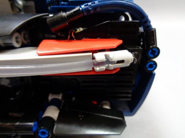
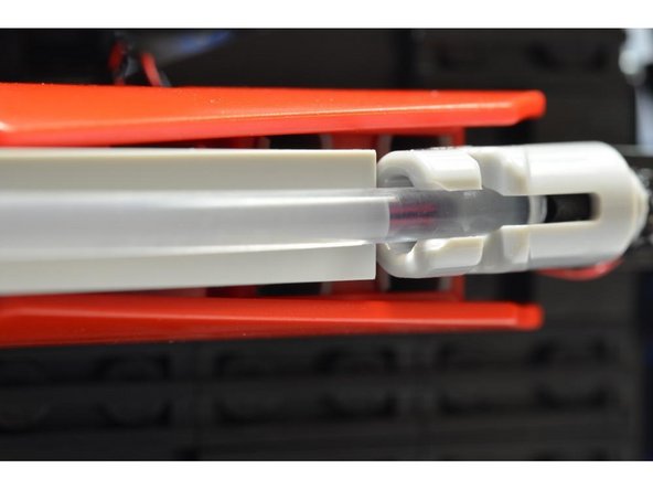
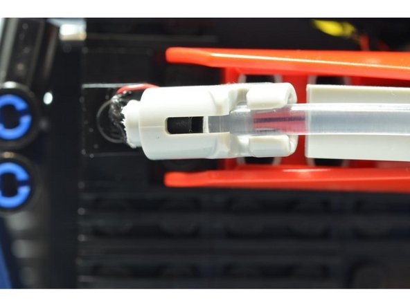
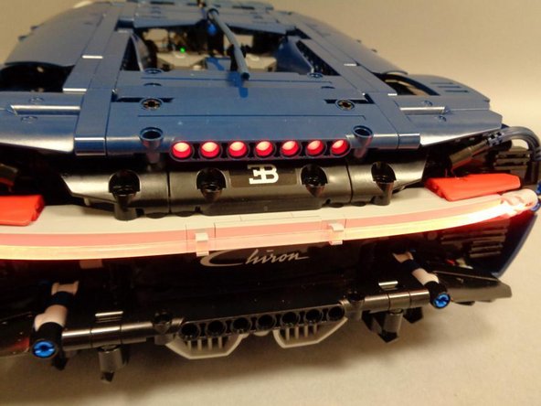
Carefully insert the long, clear fiber optic tube into the holes in the two "blaster" assemblies (one on each side of the rear of the Bugatti).
-
Note that the "blasters" have little black tubes inside to block sideways glow of the red LEDs.
-
Snap the clear fiber optic tube into place on the rear of the car.
-
For daytime display, you can still use the original red piping that came with your LEGO® set-- just remove the Brickstuff clear tubing and replace with the original LEGO® red tube.
-
Note that the Brickstuff red LEDs will not illuminate the original LEGO® red tube.
-
-
-
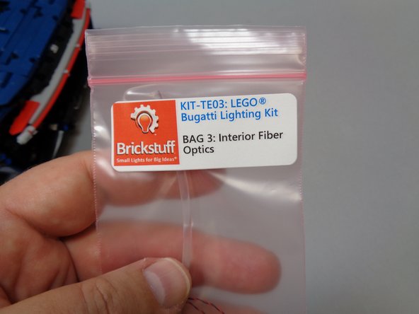
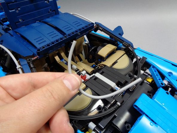
Now you will install the interior fiber optic tubing and Pico LED light. These parts are included in Bag 3 (labeled "Interior Fiber Optics").
-
As shown in the second photo, carefully remove the light bluish gray hose inside the car.
-
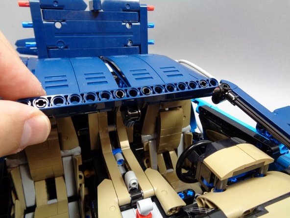
As shown in the third photo, tilt up the front Technic beam to make it easier to remove the center mount.
-
-
-
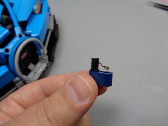
As shown in these three photos, remove the center mount from the roof beam, and then feed the cable of the cool white Pico LED through the Technic pin hole.
-
As shown in the third photo, the LED cable should come through the slot in the black Technic pin, and the LED should bend to face toward the blue Technic beam.
-
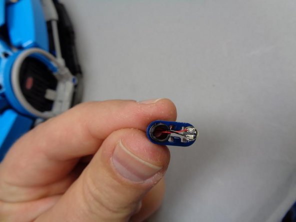
The "front" of the LED is the side opposite where the wires are soldered. You can see a small white rectangle on the front of the Pico LED-- this is the LED chip itself.
-
-
-
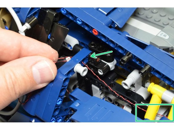
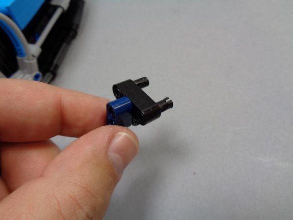
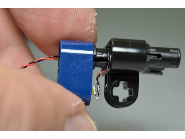
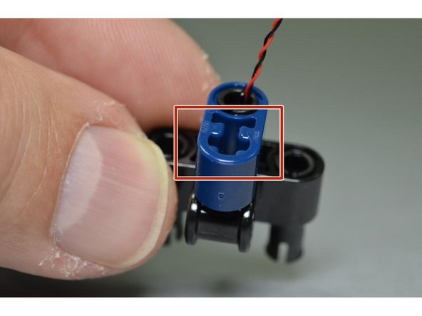
Now you will re-attach the small blue Technic beam to the black mount.
-
The Pico LED cable is strong enough to be inserted along with the black Technic pin, but be careful not to twist the pin while inserting. Also make sure the wires are coming out of the slot in the side of the pin before inserting.
-
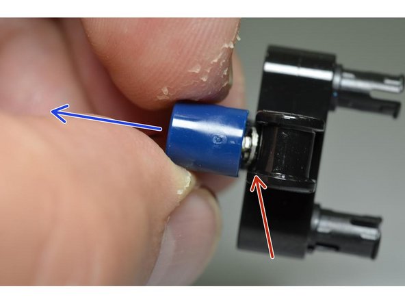
Carefully re-attach the small blue Technic beam to the black mount, taking care to make sure the Pico LED is aligned with the open hole in the blue mount (red arrow, second photo) and facing backward (blue arrow, second photo).
-
As shown in the third photo, after re-attaching, the Pico LED cable should extend out through the center of the black Technic pin and the Pico LED should face so it is pointed out the T-shaped hole in the blue Technic beam (red csquare, third photo).
-
-
-
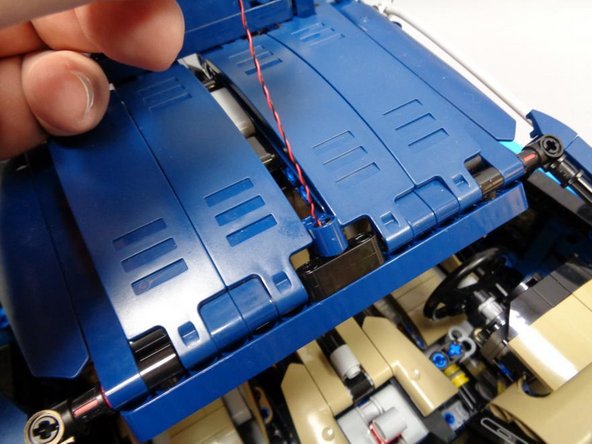
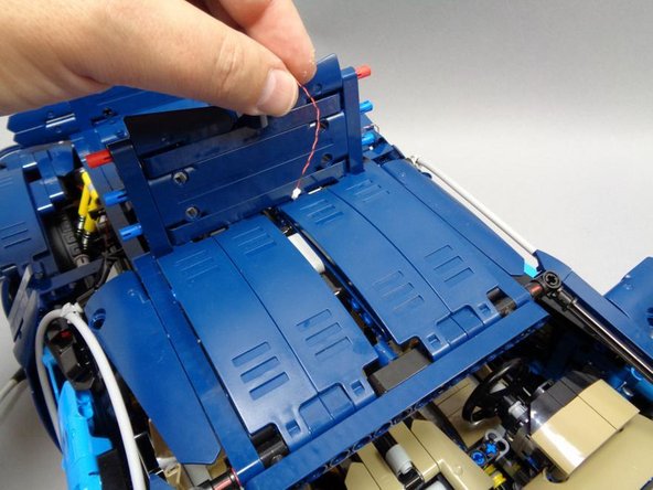
Re-attach the mount assembly to the roof of the Bugatti as shown in the first photo.
-
As shown in the second photo, run the Pico LED cable back under the top of the roof to the area where all the wires and controller board are located.
-
Carefully bend the short clear fiber optic pipe included in Bag 4 and insert it the same way as the original LEGO® tube that came with your Bugatti. (see the third photo)
-
-
-
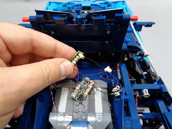
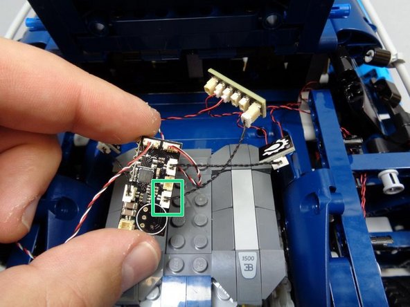
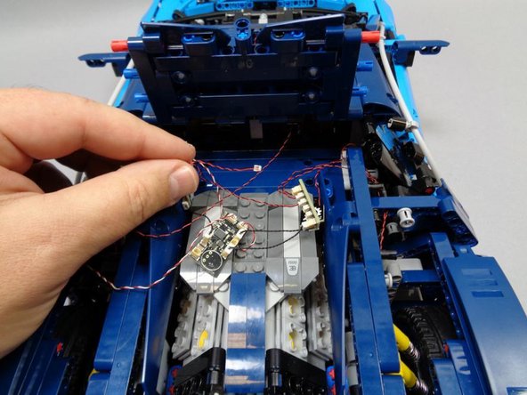
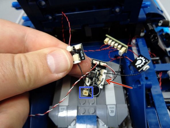
Taking the Pico LED cable you routed in the last step, connect it to one of the small connectors on the last BRANCH03 adapter board from Bag 1, and use the last 1.5" black connecting cable to connect the interior LED to the last open plug on the master control board as shown by the red arrow in the third photo.
-
Now would be a good time to double-check that you have all lights connected to the correct plugs on the main controller board. Only one plug should still be open: the single plug at the bottom of the board (blue square, third photo). This is where you will connect the power supply in a later step.
-
-
-
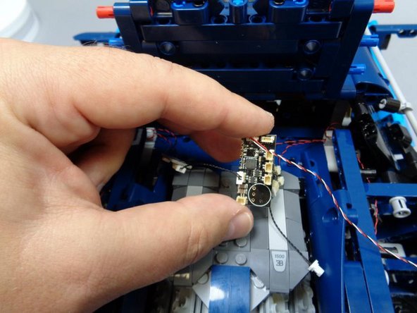
Now you will mount the infrared receiver so it has line of sight to the infrared remote control.
-
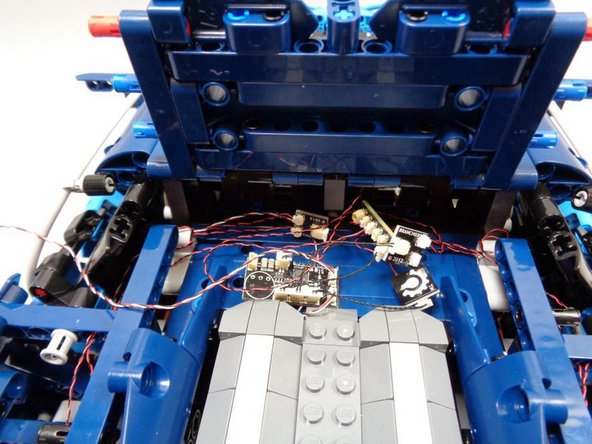
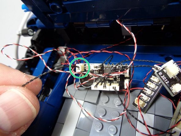
As shown in the first photo, you will have somewhat of a jumble of wires collected in the rear back of your Bugatti. You can use some of the included sticky squares to mount adapter boards to the flat panel in front of the engine or elsewhere in the area under the roof where the wires will be hidden once the roof is closed again.
-
If you will be using an AA battery pack to power your model, do not attach any wires or adapter boards using sticky squares, as the battery pack needs to be able to slide into the space in front of the engine (on the flat panel under the roof). The next step discusses how to mount the battery pack.
-
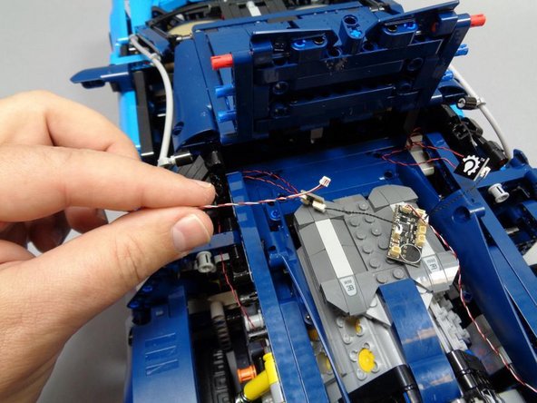
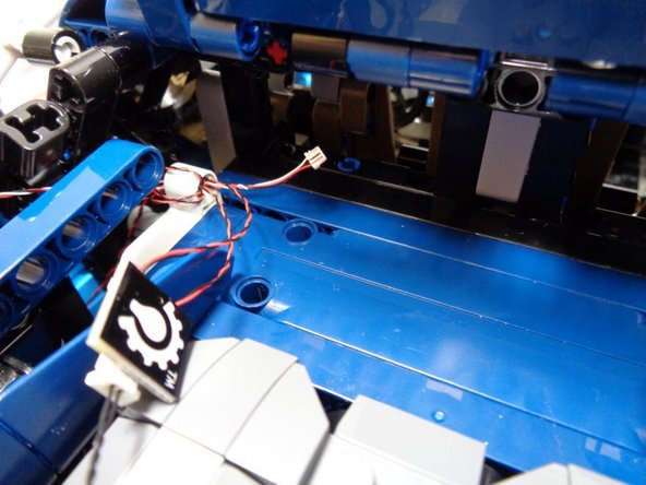
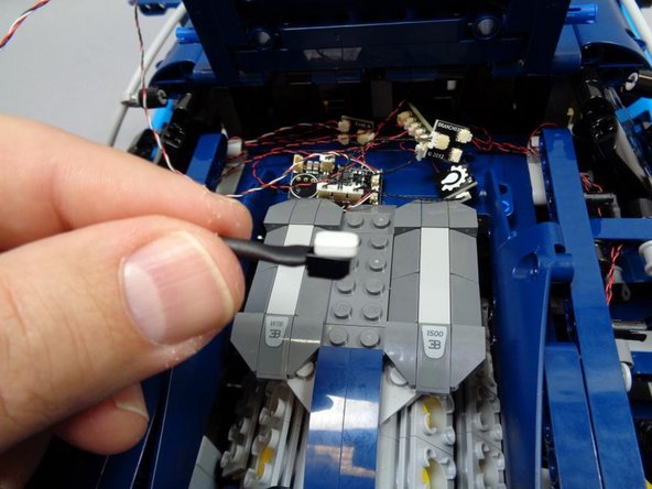
As shown in the second and third photo, use one sticky square to mount the infrared sensor in a location where it has line of sight to the exterior of the car.
-
In the third photo, we demonstrate mounting the infrared receiver in the center channel of the roof, but this is also where you will later re-attach the long blue tube, so you may decide to mount it in a different location.
-
Note that the front of the infrared receiver is the side with the little black bubble of plastic. The back of the receiver is the flat side. The receiver must be mounted with the front side facing up/out in order to receive signals (don't attach the sticky tape to the front side of the receiver).
-
-
-
Your lighting kit includes a USB cable for power, but if you want to have your Bugatti lighting 100% self-contained, you can also use our 3AA battery pack (sold separately) to power the set. This step shows how to mount the battery pack if you decide to use it instead of the USB cable.
-
You can skip this step if you do not plan to use the battery pack.
-
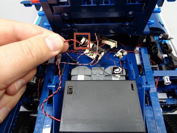
The battery pack fits perfectly in the flat space behind the seats and under the roof. Connect the battery pack cable to the last open plug on the main control board (red square int he first photo).
-
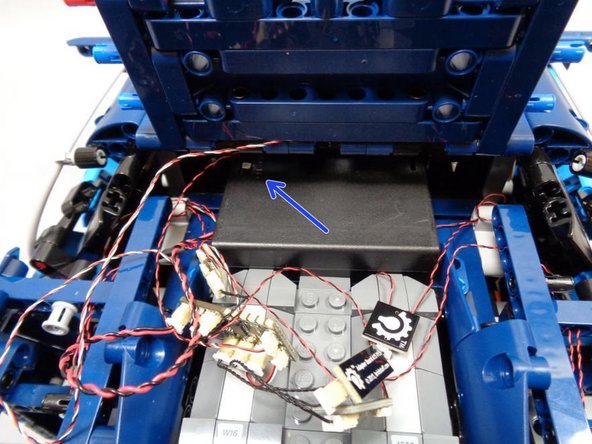
Carefully slide the battery pack into the open space behind the seats, making sure the switch is facing to the left (blue arrow, second photo).
-
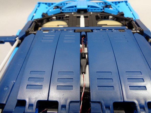
Carefully gather all wires and adapter boards, and slide them into the area above the battery pack (between the battery and the roof of the car). Make sure the roof section will close on top of everything and not crush any wires or boards.
-
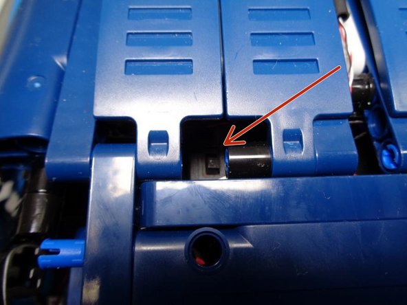
As shown in the third photo by the red arrow, the on/off switch for the battery pack should be visible through the gap between the roof panels. This makes it easy to turn the power on or off using a tweezers or pen tip even when the car is closed up.
-
-
-
Only complete this step if you will not be using the 3AA battery pack and you will be using the USB power cable instead.
-
There should be a 12" black connecting cable in Bag 1, along with a BRANCH04 adapter board. You will use both parts now.
-
As shown in the first photo (green circle), connect one end of the 12" black connecting cable to the last open connector on the main control board.
-
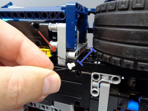
As shown in the second photo, turn the car on its side and carefully route the black cable down to the bottom of the car (see the blue line in the second photo), making sure to avoid the tires so the wire will not get caught when the car moves.
-
As shown by the red arrow in the second photo, wrap the black cable around the light bluish gray Technic beam to secure it, so it won't come loose later and get caught in the wheels.
-
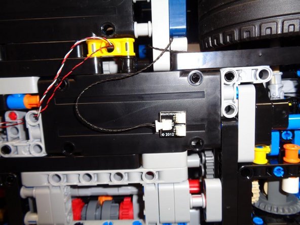
As shown in the third photo, connect the other end of the 12" black cable to one of the plugs on the BRANCH04 adapter board, then use a sticky square to attach the BRANCH04 board to the bottom of the car.
-
Make sure the car can still freely roll with the BRANCH04 adapter board attached. There should still be enough ground clearance.
-
You can connect the USB cable to either of the two remaining plugs on the BRANCH04 adapter board to power your lighting setup. Having the power connections on the bottom of the car makes it easier to connect/disconnect for transport without having to open the car up again.
-
-
-
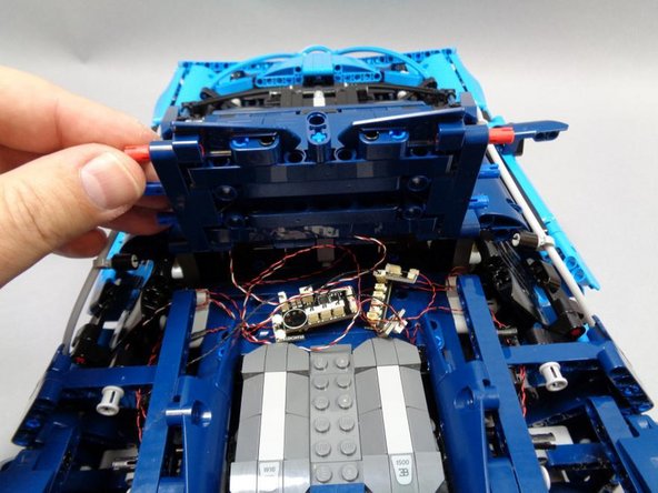
You should now have all lights, wires, and adapter boards mounted and secured. The first photo shows the jumble of wires and boards-- it may look messy, but everything should still fit in the space under the roof when it is closed.
-
If you will be attaching the spoiler add-on kit, skip to Step 41 to connect those lights before closing up your Bugatti, then come back to this step.
-
As shown in the second and third photos, close the roof, re-attach the left and right Technic beams, and re-attach the left-side roof panels.
-
Wires and adapter boards should not be visible once the roof is closed (wires should not hang down over the engine).
-
-
-
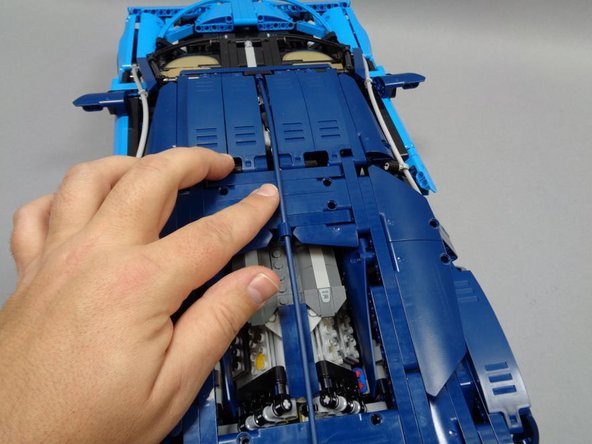
As shown in the first photo, re-attach the right-side Technic panels.
-
As shown in the second photo, carefully re-attack the long blue tube.
-
Because of the Pico LED cable inside the black Technic pin at the front of the roof, it may be difficult to fully insert the blue tube in the front. Push carefully so you don't damage the Pico LED wires.
-
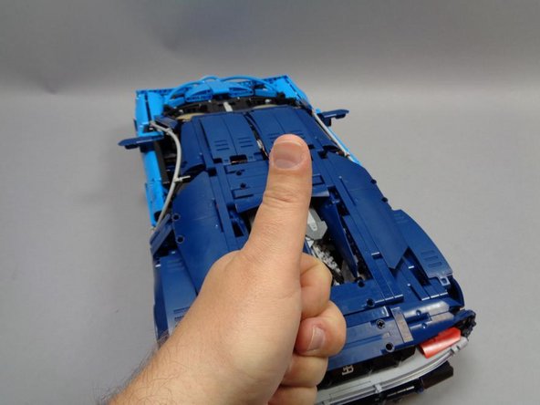
Give yourself a thumbs-up for completing your lighting installation!
-
-
-
In addition to the main Bugatti lighting kit, we also sell an add-on kit that includes the spoiler with seven red LEDs pre-mounted. This section shows how to install the spoiler and connect its LEDs.
-
If you don't have the spoiler add-on kit, you can move to Step 45 to see how the remote control works.
-
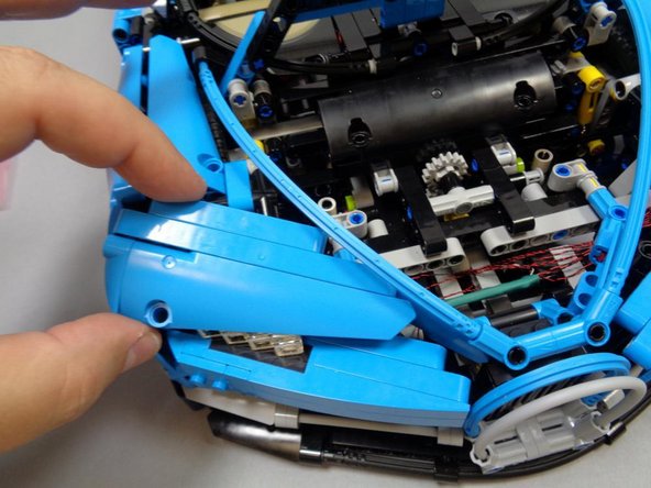
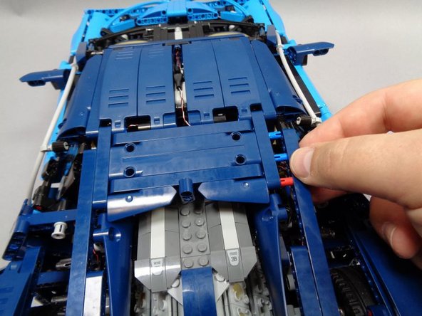
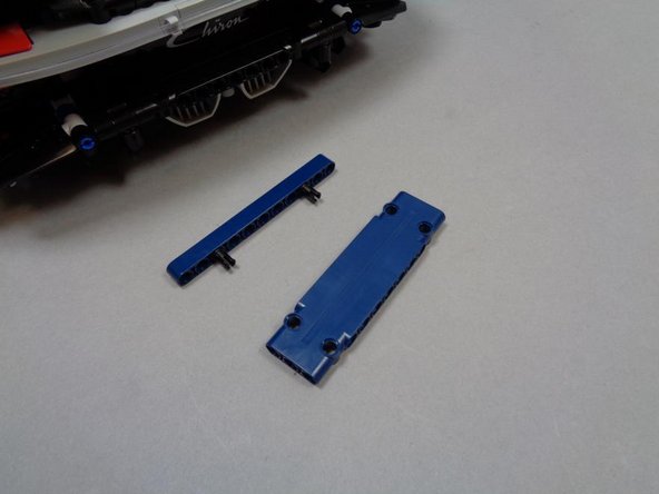
As shown in the three photos in this step, carefully remove the main spoiler panel from its fins and mount, and remove the blue Technic beam behind the spoiler panel.
-
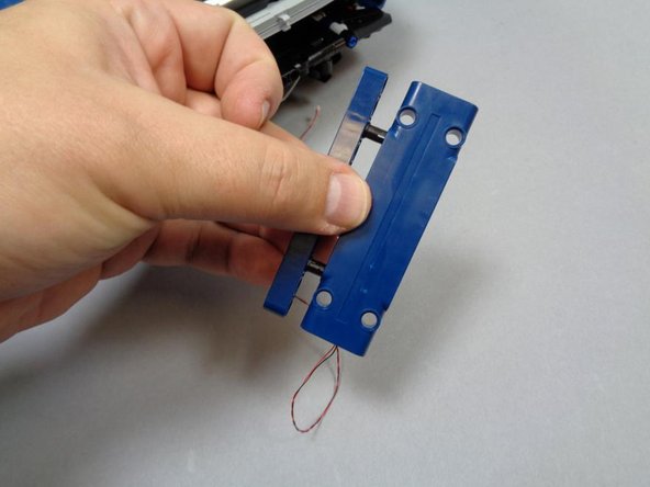
As shown in the third photo, re-attach the the blue Technic beam to the pre-lit spoiler panel provided with the add-on kit.
-
-
-
Re-attach the spoiler to the car, and carefully run the LED cable down the left side and loop the wires through the holes in the interior Technic beam as shown.
-
Be careful to loop the wires only through the innermost Technic beam and not through the outer beams. This is so the spoiler will still be able to open and close smoothly without pinching any wires.
-
-
-
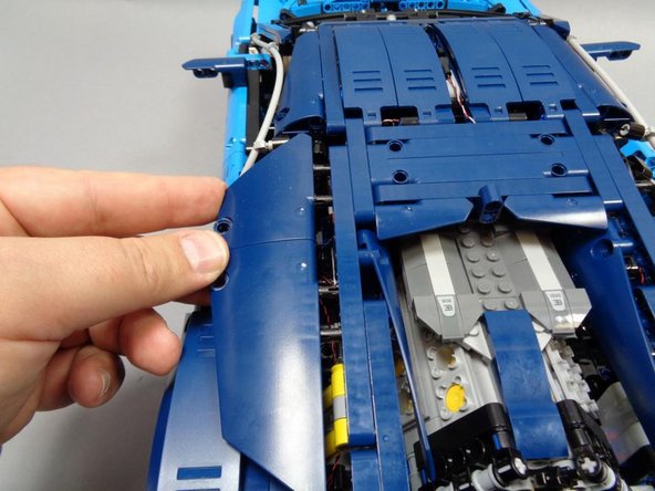
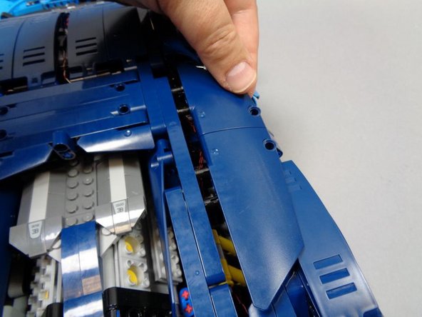
As shown in the first two photos, remove the two rear side panels and left/right beams if needed to allow the rear roof section to open up.
-
Route the wires as shown in the second photo, making sure the wires go behind the yellow shock absorbers as shown by the red square.
-
As shown in the third photo, connect the spoiler LED cable to one of the available small connecting plugs on the BRANCH15 adapter.
-
The spoiler LED cable will just reach the BRANCH15 adapter board-- make sure you have routed the wiring so there is no extra slack, or the cable may not reach.
-
Close up your Bugatti and re-attach the beams and panels you removed at the beginning of this step.
-
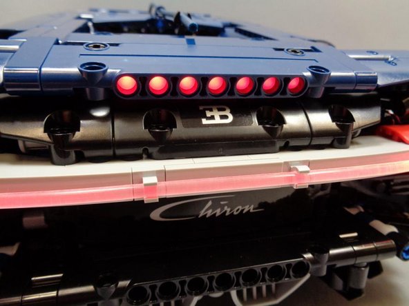
The spoiler LEDs will now turn on and off along with the main tail light (fiber optic bar).
-
-
-
The pre-lit spoiler should still move up and down as freely as it did before you installed the LEDs. Check to make sure you can still open and close the spoiler, and that it stays up when open.
-
-
-
When power is turned on (either via a connected USB cable or AA battery pack with the switch turned on), the lights in your Bugati will respond to the infrared remote control included with your kit.
-
Note that the remote control uses some infrared "command codes" that are similar to codes used by other infrared remotes such as DVD players and cable boxes. If you find the lights in your Bugatti being controlled by other remotes, you can re-position the infrared receiver on the car so it does not have such clear line of sight to the outside.
-
-
-
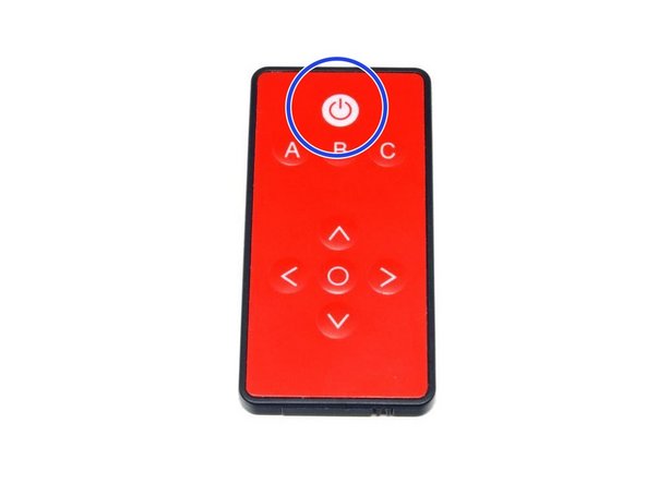
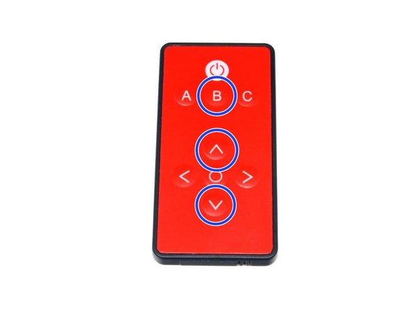
The main power button on the remote (blue circle) turns master power on or off to the entire setup.
-
The master control board inside the Bugatti remembers its settings even when power is off.
-
If your Bugatti lights appear unresponsive (pressing other buttons on the remote does not control lights), it is likely that the master power is off. Press the main power button one time (to turn on master power), then try the other buttons again.
-
-
-
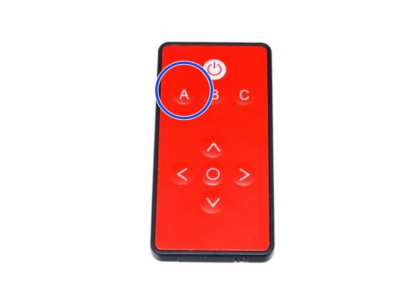
The "A" button on your remote (blue circle) controls the headlights. Pressing it once will start the "on" sequence, and each of the eight LEDs in the headlight assembly will turn on in a pattern modeled after the "real" Bugatti. Pressing the button again will turn the headlights off via a similar lighting sequence.
-
If you turn the headlights on and then press "A" again quickly before the turning on sequence has completed, the "on" sequence will still finish, immediately followed by the "off" sequence.
-
If you are pressing the "A" button but the headlights don't come on, the master power may be off. Press the main power button once, then try pressing "A" again.
-
-
-
The "B" button (top blue circle) turns the interior (fiber optic) LED on or off, and the up and down arrow buttons (other two blue circles) control the lighting pattern for the interior light. There are several lighting patterns included:
-
Dim
-
Brighter
-
Brightest
-
Slow Pulse
-
Medium Pulse
-
Fast Pulse
-
Pressing the up or down buttons while the interior light is on will cycle through these patterns.
-
-
-
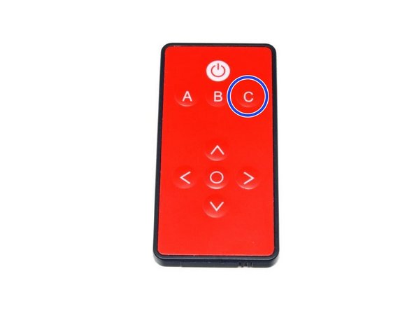
The "C" button turns the rear tail light (and also the optional spoiler lights) on and off.
-
If you are pressing the "C" button but the tail lights don't come on, the master power may be off. Press the main power button once, then try pressing "C" again.
-
-
-
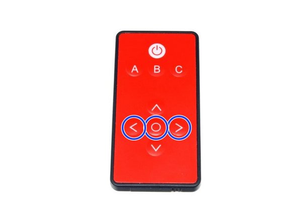
The three buttons highlighted with blue circles in the photo control the turn signals and hazard lights:
-
The left arrow button turns the left turn signals on and off.
-
The right arrow button turns the right turn signals on and off.
-
The center circle button turns the hazard lights on and off.
-
If you are pressing buttons but the blinkers don't come on, the master power may be off. Press the main power button once, then try pressing the blinker buttons again.
-
-
-
Thank you very much for purchasing this Brickstuff Premium lighting kit! We hope you enjoy it as much as we enjoyed making it for you.
-
If you have any problems, questions, or trouble, don't hesitate to e-mail us at support@brickstuff.com and we will do whatever we can to help get you up and running.
-
If you like your lighting setup, please post photos and videos online and use a #brickstuff hashtag so we can see them and share with other customers!
-


Cancel: I did not complete this guide.
8 other people completed this guide.

One Comment
A nice feature for your Bugatti.
The building was not easy but the guide was good
René Wolfs - Resolved on Release Reply