
Tools
Parts
Featured Document
-
-
If you have already installed your kit and would like to skip to instructions describing operation, click here.
-
There are several ways to read this guide:
-
Reading it on the web in your browser.
-
Downloading a PDF copy of the guide. You can do this by selecting "Download PDF" as shown by the red rectangle in the first photo. Click on the Options heading in the upper right corner of the screen (see the green rectangle).
-
In the "Dozuki" application, which is available for download from the Apple App Store and various Android and Google marketplaces.
-
If you view this guide in the Dozuki app, search for "Brickstuff" the first time you open the app, then select "Product Guides" from the categories listed under Brickstuff. Scroll down to find this guide.
-
You can also translate this guide into another language when viewing on the web. To do this, install a translator extension into your browser and use that extension/plug-in to translate the page. Using the main Google translate website (translate.google.com) does not work.
-
-
-
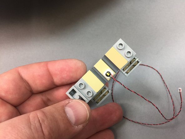
As shown in the first photo, it is very important to look at the color of the wires for the lights in this kit.
-
Lights with red and black wires can be connected to any adapter their plugs will fit into.
-
Lights with blue and white wires can ONLY be connected to either a BRANCH09 or BRANCH09X adapter board. Connecting a light with blue and white wires to any other adapter board (including other adapters where the plugs fit) will destroy the light.
-
The second photo is a visual reference for the controllers and adapter boards included with your kit. You may want to print a copy to reference as you walk through the instructions. You can download a PDF copy of this illustration here.
-
Here are some other very important tips to keep in mind as you connect the parts in this kit:
-
Plugs connect to adapter boards and controllers only one way. Do not force plugs.
-
Do not remove plugs with tabs by pulling on the wire. Always use your fingernails or tweezers to remove plugs by pulling on the tabs of the plug, not the wires.
-
Many boards have connectors that face vertically (upward). Use extra care when connecting or disconnecting plugs to these connectors. Pulling or pushing sideways on any vertically-facing plug can cause the plug to come detached from its circuit board.
-
-
-
Note that this guide applies only to "Version 2" light + sound kits for the Falcon-- these are the kits sold beginning with the November 2019 batch of orders. If your kit was part of an earlier batch, these instructions will not be relevant. Contact us if you have misplaced the printed guide that was included with your kit.
-
Depending on when your kit was manufactured, it may have one of two different designs of TRUNK08 master controller included.
-
The TRUNK08 master controller is included inside the pink bag labeled Main Control and Connecting Parts.
-
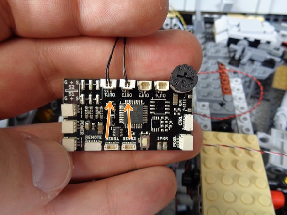
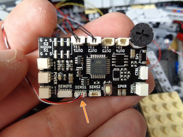
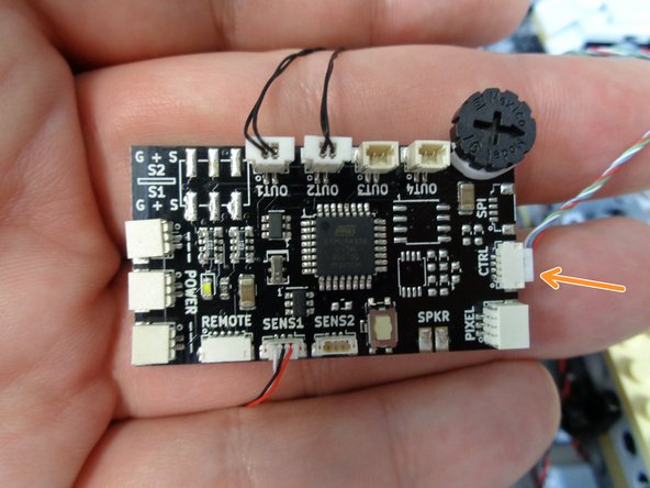
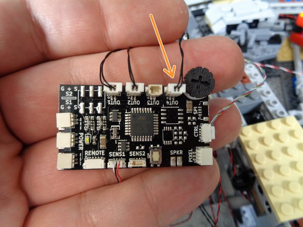
The first photo in this step shows the version 4 TRUNK08 controller. This controller has a black dial in the upper right corner, and it also has top-facing plugs for the OUT1, OUT2, OUT3, and OUT4 connectors.
-
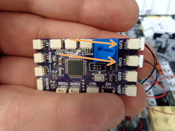
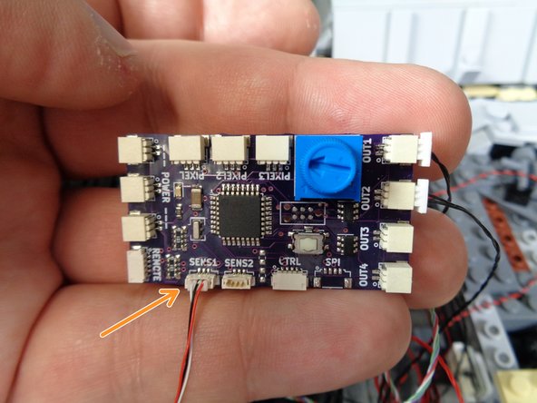
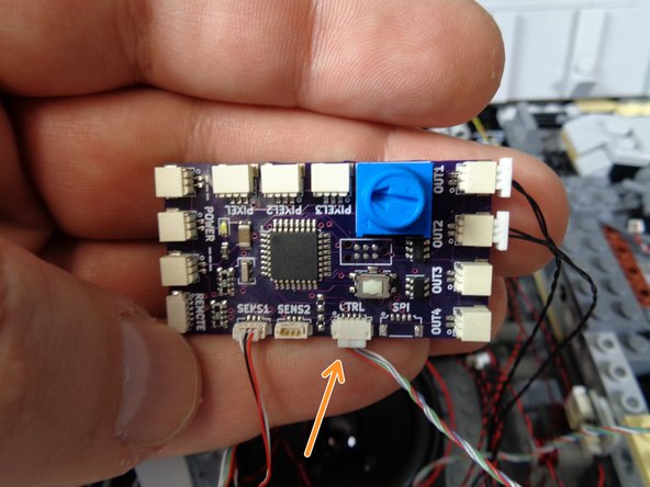
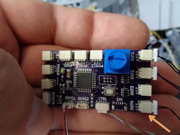
The second photo in this step shows the version 7 TRUNK08 controller. This controller has a blue dial in the upper right corner, and it also has side-facing plugs for the OUT1, OUT2, OUT3, and OUT4 connectors.
-
Both controllers operate identically, and plugs are labeled the same with the exception of the Version 7 controller having three "pixel" output plugs while the Version 4 controller has only one "pixel" output plug. If your kit has a Version 7 controller, you will only use the "PIXEL1" plug to connect adapter boards,
-
-
-
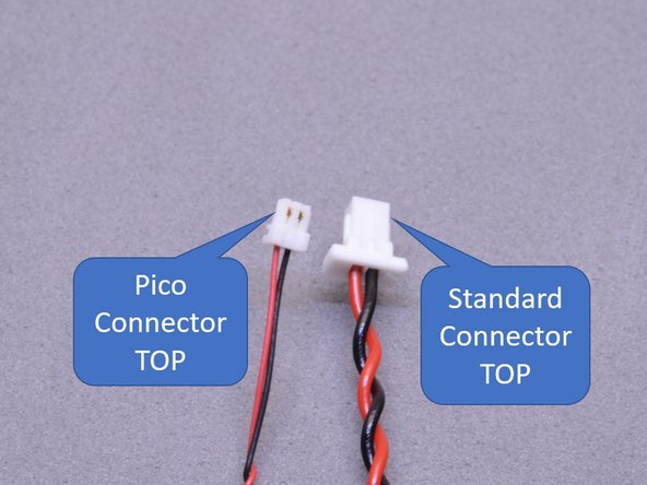
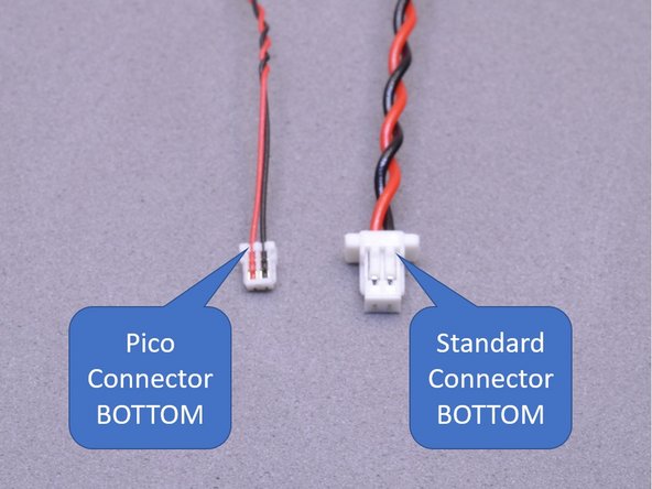
When connecting plugs, it is important to be able to tell the top of the plug from the bottom. The first photo in this step shows the top of two different types of plugs, and the second photo shows the bottoms.
-
Plugs will fit into connectors only one way. Do not force!
-
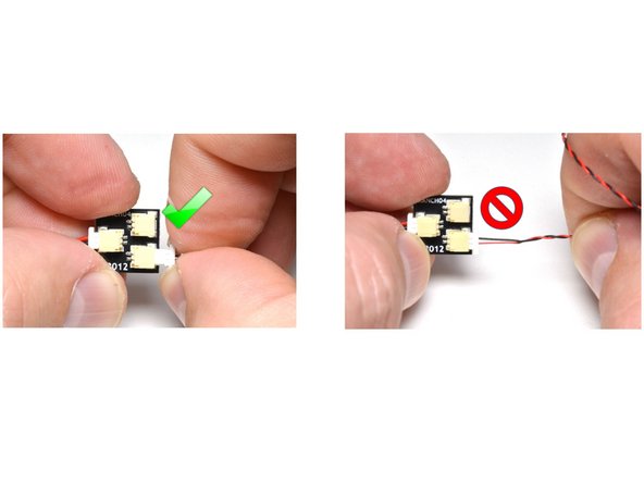
When removing plugs, to not pull from the wire. As shown in the third photo in this step, use your fingers to pinch the tabs on larger plugs and pull on the tabs to remove.
-
The connectors in this kit can hold plugs very tightly. Pulling on the wire instead of using the tabs on larger plugs will cause the wires to pull out. Once a wire pulls out from a plug, it cannot be repaired.
-
-
-
You will be running a lot of wires during the installation of this kit. Because the Millennium Falcon model is constructed using many LEGO® Technic parts, there are many holes and gaps through which you can run the wires. You can use the Technic parts to secure wires by wrapping excess wire around the Technic elements.
-
You can also use a tweezers or pencil to coil excess wire to prevent it from getting caught in gaps.
-
The first photo in this step shows a wire with standard-size connector passing between two Technic bricks.
-
The second photo in this step shows that standard-size connectors will not pass through Technic stud holes.
-
The third photo in this step shows that wires can be held in place by snapping plates or tiles on top of the wires.
-
Whenever you snap a LEGO part on top of a wire, make sure to run the wire BETWEEN, not on top of, any studs.
-
-
-
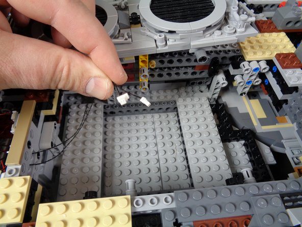
The first photo in this step shows that wires with Pico connectors can pass through stud holes, and the second photo shows that Pico connectors can even pass through Technic pins inserted into stud holes.
-
The third photo shows how excess cable can be wrapped around plates or bricks.
-
-
-
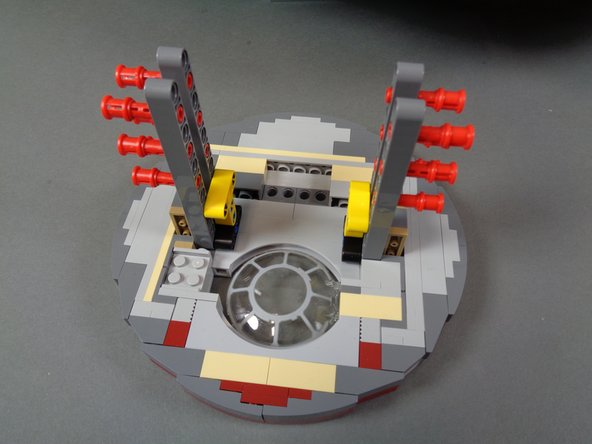
With your Falcon model placed on a flat surface large enough to allow you to rotate the model during installation, carefully remove all of the detachable top panels on the Falcon and set them aside. Also remove the two side docking bay assemblies. You will not need these parts again until the last steps of the installation process.
-
-
-
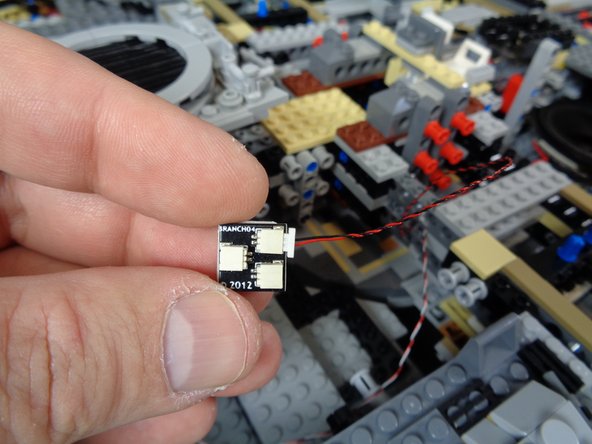
Open the Main Engine LED Light Assemblies bag, and carefully remove the two engine LED panels, the two diffuser papers, the two BRANCH04 boards, and the two black connecting cables.
-
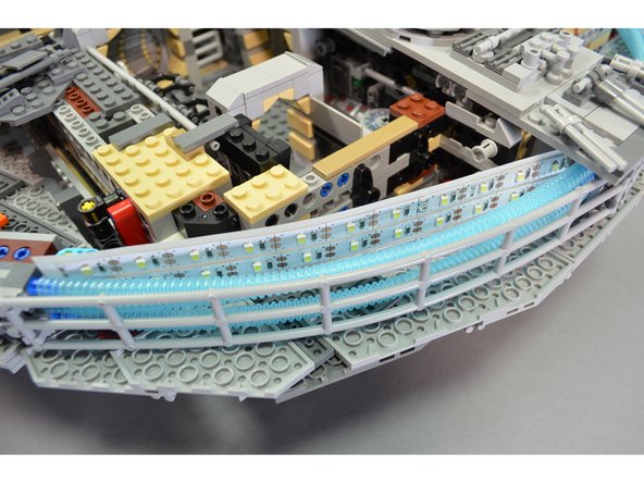
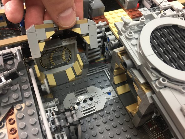
As shown in the second photo for this step, mount the engine lighting assemblies behind the blue engine tubes so the wires for each assembly face toward the center of the Falcon.
-
As shown in the third photo for this step, carefully insert the diffuser paper sections in front of the LEDs, so the diffuser is between the LEDs and the blue engine tubes.
-
-
-
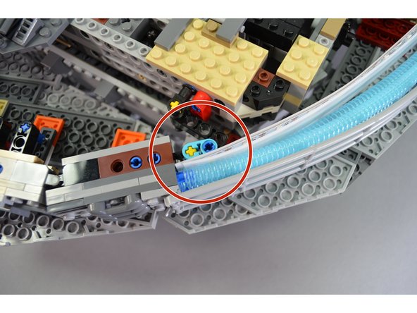
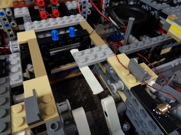
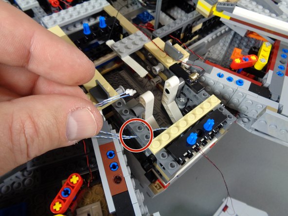
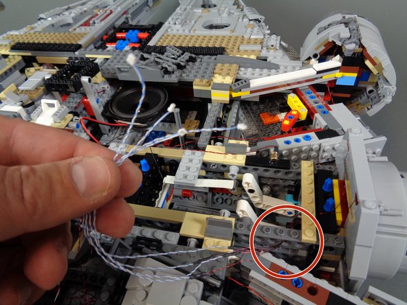
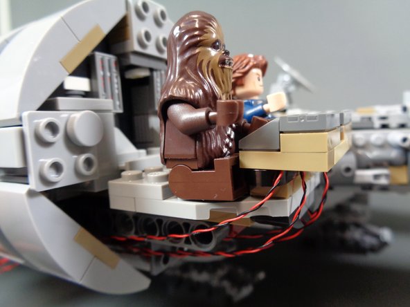
Make sure both the LED panels and the diffuser paper are secured between the turquoise Technic arm and the blue engine tubes as shown by the red circle in the first photo.
-
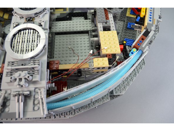
Gather the wires coming from the two LED panels into the rear right side of the Falcon as shown in the second photo. Run the wires from the left panel under the top center section.
-
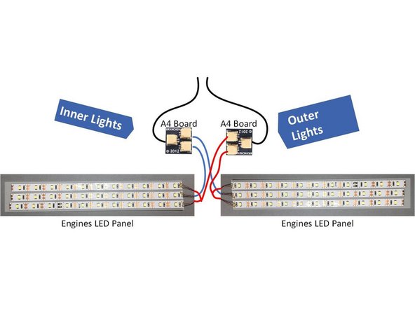
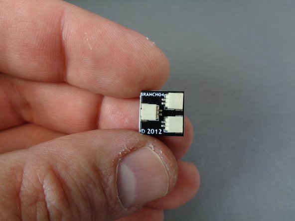
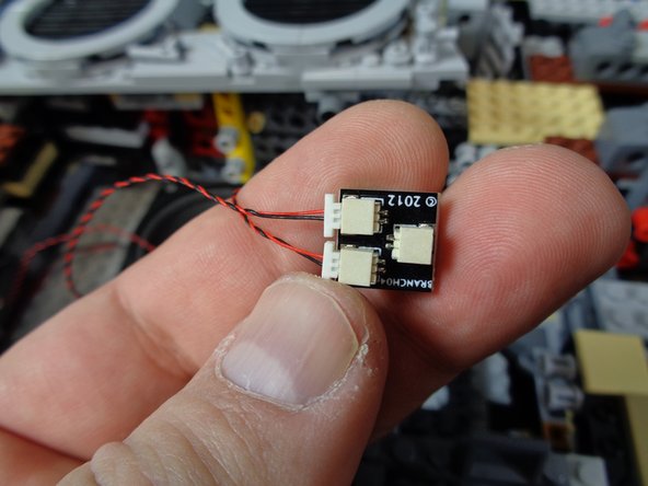
Take the two BRANCH04 adapter boards and 6" connecting cables from the Main Engine LED Light Assemblies bag and connect as shown in the third photo.
-
Note that the cables included with your kit may be black or red and black. Also, they may be thicker than the cables shown in the photos here. That is ok.
-
Note that in the illustration, the "inner" light strips and "outer" light strips from each engine panel are connected to separate BRANCH04 adapter boards. For the engine effect to operate correctly, connections from each engine panel must be connected and split in this way.
-
-
-
As shown in the first and second photos, take two large sticky squares from the bag labeled Main Control and Connecting Parts, attach one to the back of each BRANCH04 adapter board, and mount the BRANCH04 boards to the Falcon frame.
-
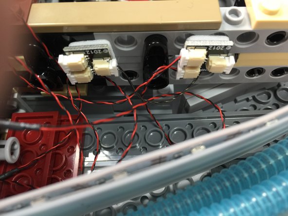
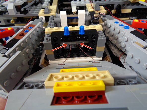
As shown in the third photo, carefully pass the two 6" connecting cable wire ends through the frame in the gap between the two long Technic bricks.
-
Note that the cables included with your kit may be black or red and black. Also, they may be thicker than the cables shown in the photos here. That is ok.
-
-
-
The photos in this step show where to connect the two engine light strips. The only difference in the photos is that one shows a Version 4 TRUNK08 master controller and the other shows a Version 7 TRUNK08 master controller. Refer to the photo that matches the version of controller included with your kit.
-
Connect the cable coming from the "outer" engine strips to the plug on the TRUNK08 master controller labeled OUT1.
-
Connect the cable coming from the "inner" engine strips to the plug on the TRUNK08 master controller labeled OUT2.
-
Remember that the plugs on the TRUNK08 master controller will grip the plugs very tightly. If you need to disconnect or re-connect any plugs, remember to pull them while holding the white tabs, NOT by the wire.
-
-
-
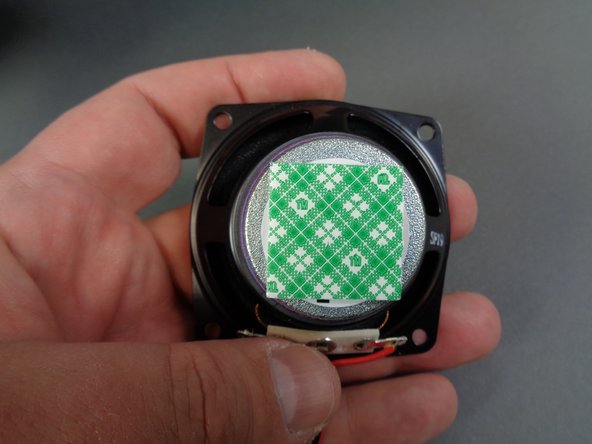
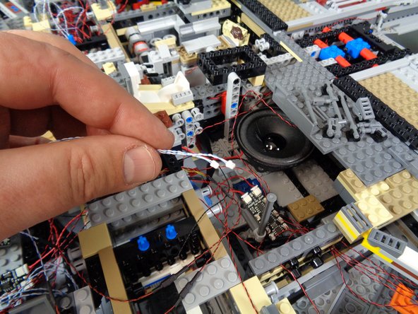
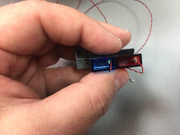
Your kit includes two different sound modules, each connected to a large speaker in a white box:
-
The "engines" sound module has a blue section of shrink tubing covering it.
-
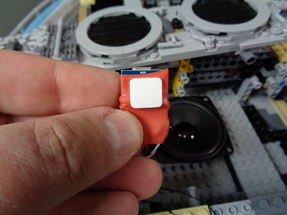
The "laser" sound module has a red section of shrink tubing covering it.
-
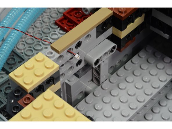
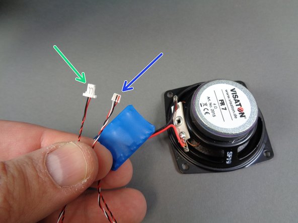
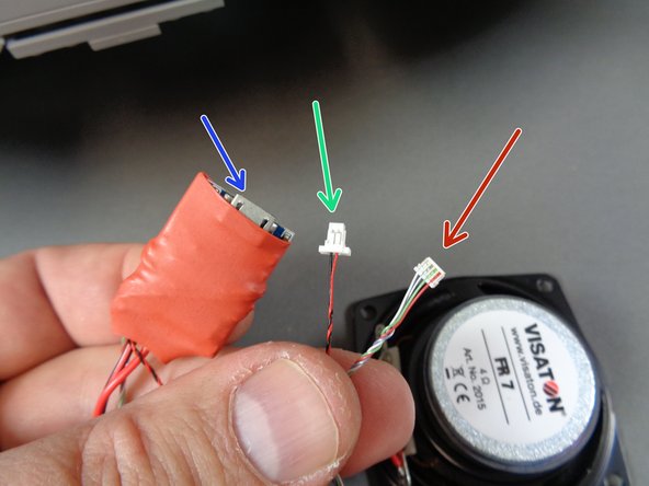
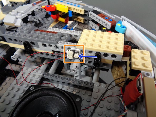
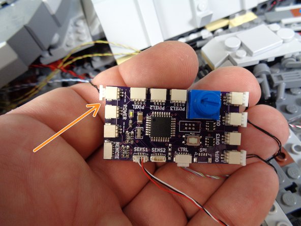
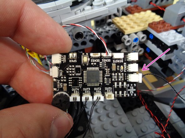
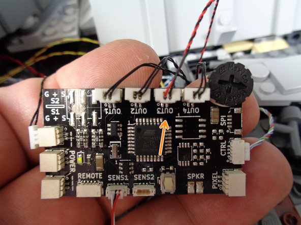
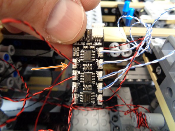
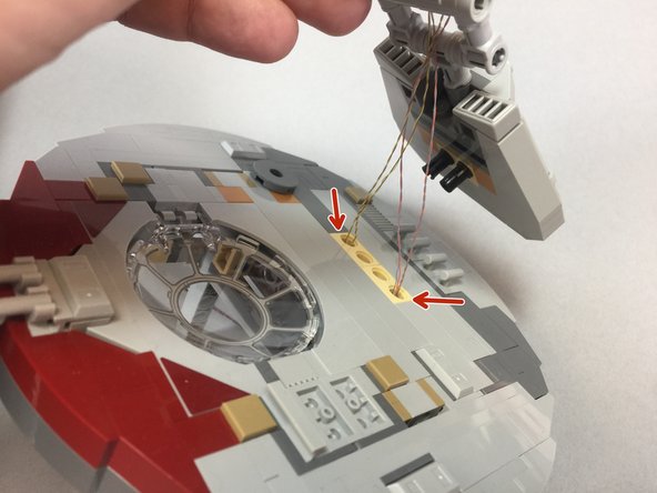
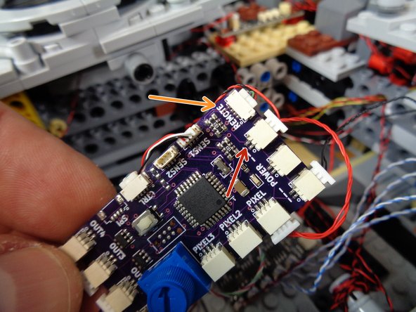
First, you will connect the "engines" sound module. The photo in this step shows the plugs on that module:
-
The green arrow in the photo points to the 2-wire power plug for the "engines" sound module.
-
The blue arrow in the photo points to the 3-wire control plug for the "engines" sound module.
-
-
-
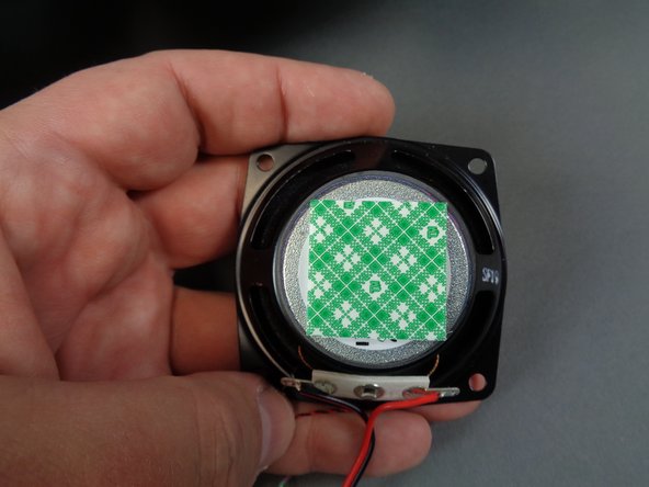
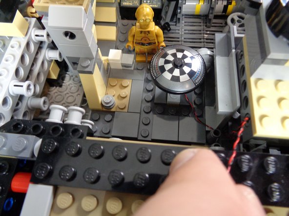
As shown in the first photo, take one of the large double-sided tape squares from the Main Control and Connecting Parts bag, and attach it to the back of the "engines" sound module speaker.
-
Note that the tape squares included with your kit may look different from the squares in the photo. That is ok.
-
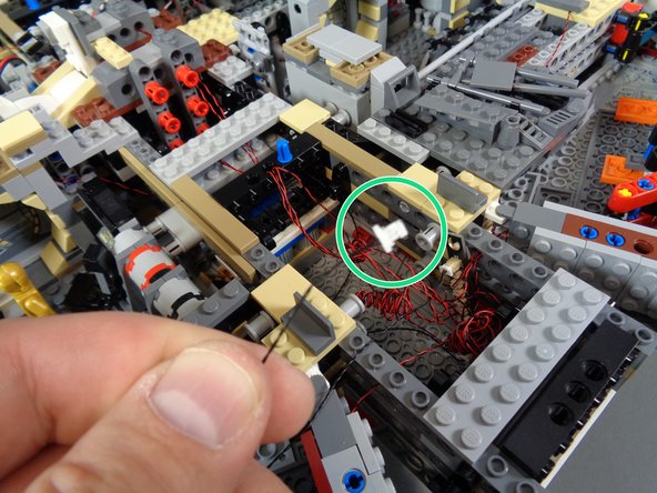
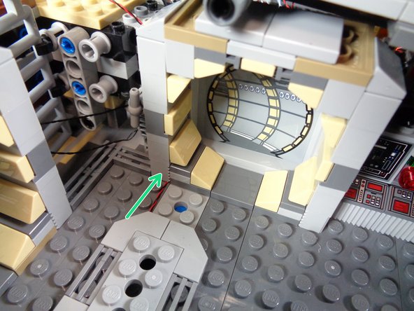
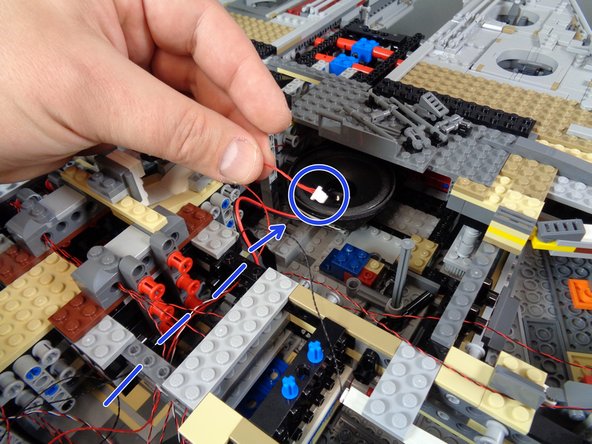
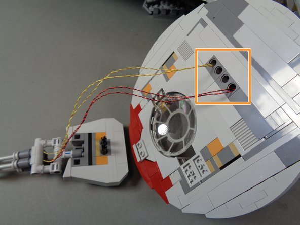
You will mount the engines speaker in the front section of the Falcon, in the area shown by the orange circle in the second photo.
-
As shown in the third photo, firmly attach the speaker to the frame of the Falcon so it faces upward.
-
There should be enough space above the speaker to allow the top Falcon panels to be re-attached without touching the speaker.
-
-
-
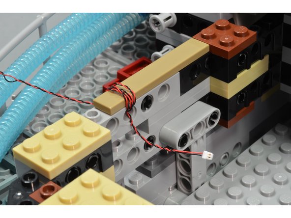
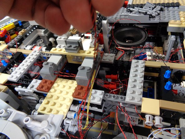
As shown in the two photos for this step, carefully feed the two wires from the "engines" sound module toward the back of the Falcon.
-
Make sure you pass the wires behind the boarding ramp area.
-
-
-
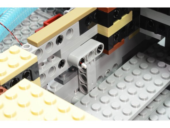
The two photos in this step show where to connect the 3-wire control cable to the TRUNK08 master controller.
-
Connect the 3-wire cable to the plug labeled SENS1 on the TRUNK08 master controller.
-
The two photos show the different versions of TRUNK08 master controller that might be included with your kit. Follow the photo that matches your controller.
-
-
-
Take the BRANCH04/A4 adapter board from the Main Control and Connecting Parts bag, and attach a large sticky square to the back of the adapter board as shown in the second photo.
-
As shown in the third photo, connect the 2-wire power plug from the "engines" sound module to one of the plugs on the BRANCH04/A4 adapter board.
-
All three plugs on the BRANCH04/A4 adapter board are electrically connected. It does not matter which plug you connect the sound module to.
-
-
-
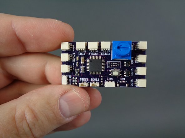
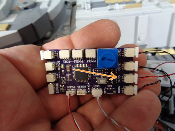
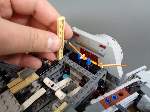
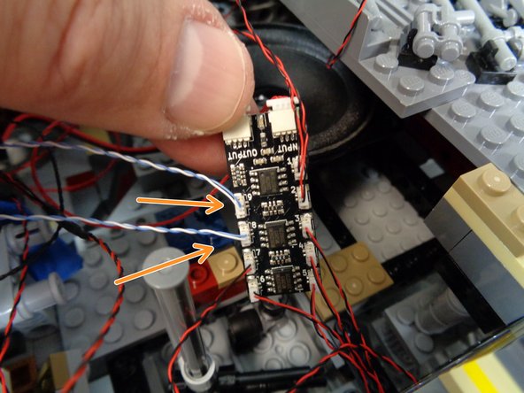
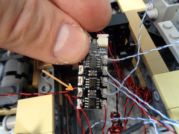
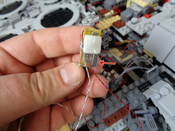
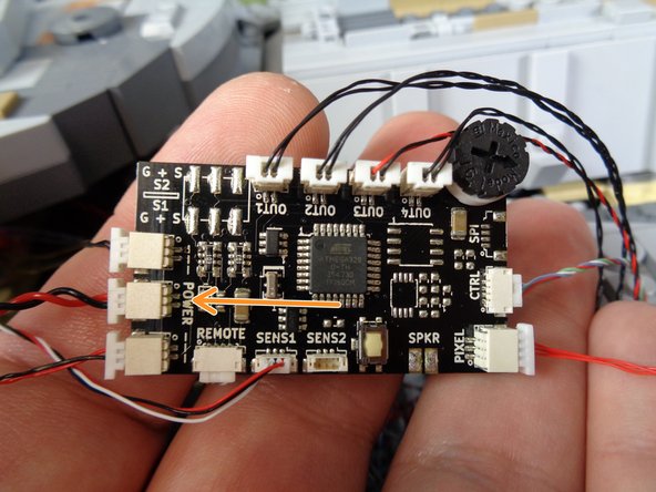
Next you will mount the "laser" sound module. As shown in the first photo, the "laser" sound module has a 2-wire power connector (green arrow) and a 4-wire control connector (red arrow).
-
As shown by the blue arrow, the "laser" sound module also has an exposed MicroUSB connector that can be connected to a computer to add custom sounds. That will be covered in more detail at the end of this guide.
-
As shown in the second photo, take the second large double-sided tape square from the Main Control and Connecting Parts bag and stick it to the back of the "laser" sound module speaker.
-
The red circle in the third photo shows where you will mount the "laser" sound module speaker.
-
-
-
Mount the "laser" sound module speaker as shown in the first photo.
-
As shown in the second photo, take a large sticky square and attach it to the back side of the "laser" sound module.
-
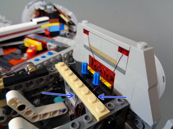
As shown in the third photo, attach the "laser" sound module to the frame of the Falcon so the MicroUSB plug is facing upward.
-
Mount the sound module as shown by the two blue arrows so the MicroUSB connector is flush with the tan tile. This will make it easier to access the USB connector later if you need to connect the sound module to your computer.
-
-
-
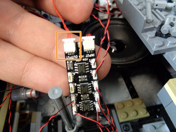
As shown in the photos for this step, connect the "laser" sound module's 4-wire control cable to the plug labeled "CTRL" on your TRUNK08 master controller.
-
Both designs of TRUNK08 master controller are shown in the photos. Refer to the photo that matches the specific controller included with your kit.
-
-
-
As shown in the first photo, connect the 2-wire power plug from the "laser" sound module to one of the other plugs on the BRANCH04/A4 adapter board. This is the same adapter that the power wire from the "engines" sound module is already connected to.
-
As shown by the orange square in the second photo, attach the BRANCH04/A4 adapter board to the frame of the Falcon.
-
When attaching the adapter board to the Falcon frame, make sure to leave enough clearance for connecting the plug on one of the power cables provided with your kit. The connection will be made where the blue arrow points. For now, you can leave the third plug on the BRANCH04/A4 adapter board open with no plug connected.
-
As shown by the red circles in the third photo, you can coil any excess wire from the two sound module power cables around the Technic pins inside the Falcon.
-
-
-
Next, you will mount the 10 landing lights to the underside of your Falcon. The landing lights are included in the bag labeled Landing Lights LEDs. This bag is contained inside the larger bag labeled Landing Lights Kit.
-
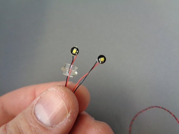
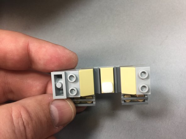
As shown in the second photo, there are two types of landing lights included:
-
One type (shown on the left in the second photo) has the light pre-mounted inside a clear round plate. There are four of these types of lights in your kit.
-
The other type of light (shown on the right in the second photo) is not pre-mounted inside a LEGO plate. There are six of these types of lights in your kit.
-
You will begin with the lights that are pre-mounted inside the clear round plate.
-
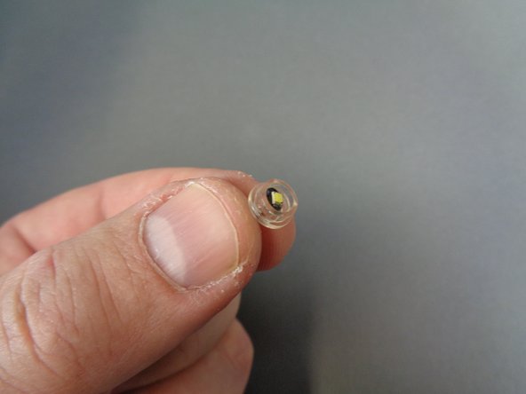
As shown in the third photo, before mounting, gently bend the light and insert it into the open area of the clear round plate. The light should fully fit inside the bottom of the plate.
-
-
-
Because the 10 landing lights need to be mounted underneath the Falcon, this section is the most difficult to complete. If you have been working straight from the beginning of the installation, it is recommended that you take a break.
-
Before proceeding, make sure you can access the underside of your Falcon. It is recommended that the model be positioned near the edge of a table, so you can access the underside of the model closest to the edge of the table.
-
Begin by attaching the four lights that are pre-mounted inside the clear round plates.
-
The orange circles in the first illustration show the approximate locations underneath your Falcon where the lights should be mounted.
-
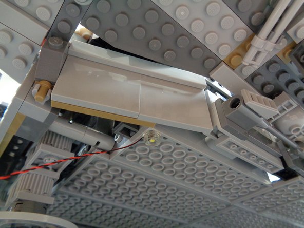
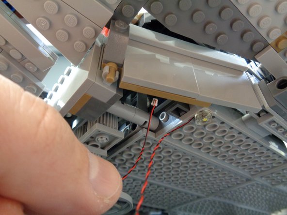
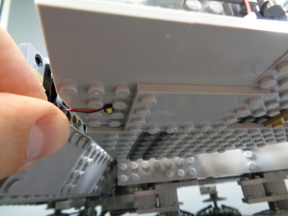
As shown in the second and third photos, attach the light to the underside of the Falcon, then pass the light's wire up into the main body of the Falcon.
-
Repeat this process for each of the four lights that are pre-mounted inside the clear round plates.
-
-
-
The six green circles in the first illustration show the approximate locations where you will mount the remaining six landing lights.
-
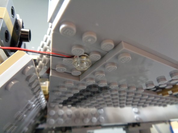
As shown in the second photo, the easiest way to mount the lights is to position them between four studs.
-
As shown in the third photo, with the light positioned between four studs, you can then attach one of the clear round LEGO plates (included in the landing lights bag) on top of the light.
-
it is ok to press the clear round plate down on top of the light's wire.
-
Repeat this process for each of the remaining landing lights, until you have mounted all 10 lights on the underside of the Falcon.
-
For each light, make sure to attach it in a location where you can pass its connecting wire up into the inside of the Falcon frame.
-
-
-
The photos in this step show some tips for running the landing light wires inside the Falcon.
-
As shown by the blue circle in the first photo, you can wrap loose wire around Technic parts inside the Falcon frame.
-
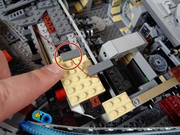
As shown by the red circle in the second photo, you can also run the light wires underneath plates and tiles. Just make sure to run the wires between--not on top of--studs.
-
As shown by the light blue rectangle in the third photo, make sure no wires run in the space between the two rows of red Technic pins at the center of the Falcon frame. The space between the pins must be kept clear to allow the top to be re-attached.
-
-
-
You should now have all 10 landing lights attached to the underside of your Falcon, with the wires for each light passed up into the main interior frame area.
-
The illustration for this step shows how to route the wires for each light, and where to connect the lights to adapter boards. You can download a high-resolution copy of this illustration here.
-
To connect the landing lights, use the following parts from the pink bag labeled Landing Lights Parts:
-
BRANCH10/A10 adapter board and BRANCH03/A3 adapter board
-
12" (30.48cm) connecting cable and 24" (60.96cm) connecting cable. Note that these cables may be black or black/red. They may also be thicker than the cables shown in the photos. That is ok.
-
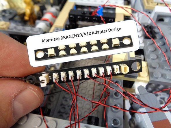
The illustration shows the approximate location inside the Falcon where the BRANCH10/A10 and BRANCH03/A3 adapter boards should be located. Note that depending on when your kit was made, your BRANCH10/A10 adapter board may look different than in the illustrations. Connections to the board are still the same.
-
In the illustration, note that the 12" connecting cable is blue and the 24" connecting cable is green.
-
Connect one end of the 24" connecting cable to the BRANCH10/A10 adapter board and run the wire back into the right rear of the Falcon, close to the TRUNK08 master controller.
-
-
-
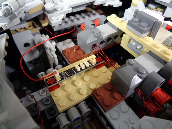
Using the illustration in the previous step as a guide, connect two landing lights to the small connectors on the BRANCH03/A3 adapter board as shown in the first photo. Connect one end of the 12" connecting cable to the large plug on the BRANCH03/A3 adapter.
-
Landing lights that are pre-mounted inside the clear round LEGO plates have 12" cables. The other landing lights have 24" cables. Pick two landing lights with 12" cables to attach to the BRANCH03/A3 adapter board.
-
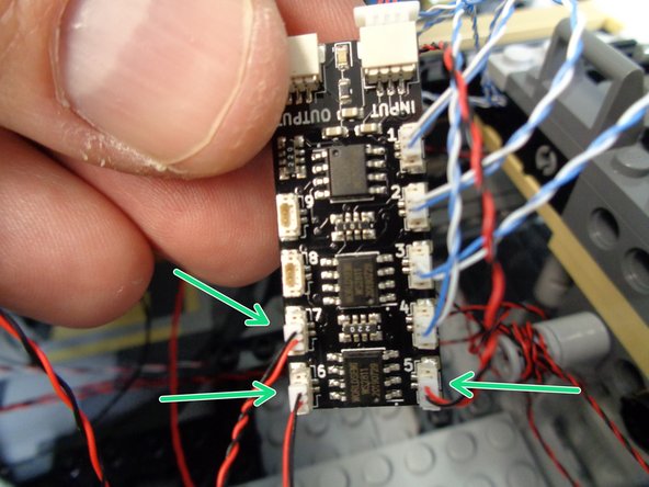
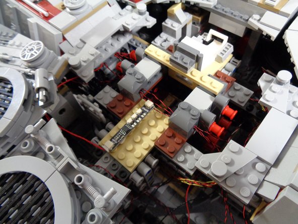
As shown in the second photo, connect the other end of the 12" connecting cable to one of the large plugs on the BRANCH10/A10 adapter board, then connect the remaining eight landing lights to the small plugs on the adapter board.
-
Depending on when your kit was manufactured, your BRANCH10/A10 adapter may look like the one in the inset in the second photo. If you have this version of the adapter with side-facing connectors, it functions the same way as the version with top-facing connectors.
-
All of the plugs are electrically connected, so it does not matter which specific plugs you use.
-
After you have connected the remaining eight landing lights to the BRANCH10/A10 adapter board, connect one end of the 24" connecting cable to the other large plug on the BRANCH10/A10 adapter board.
-
As shown by the green arrows in the third photo, use one or two small sticky squares to attach the BRANCH10/A10 adapter board to the inner wall of the right docking bay.
-
Note that some of the lights with 12" cables will need to be routed carefully as they are just long enough to reach the BRANCH10/A10 adapter board.
-
-
-
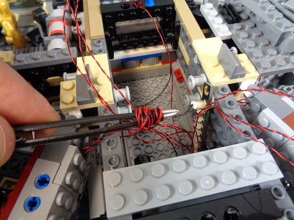
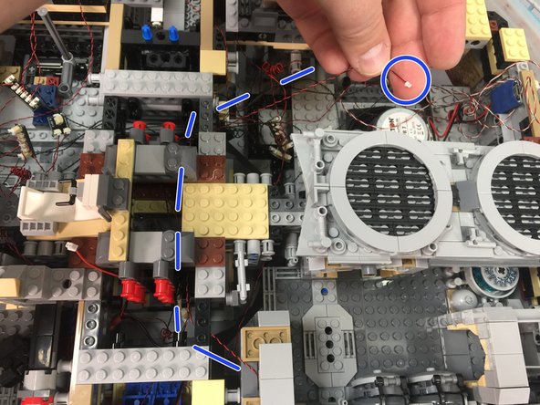
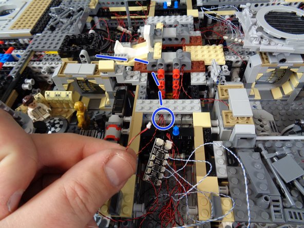
You will have a lot of excess wire inside the right docking bay area. As shown in the first photo, you can use a tweezers to coil the excess wire so it all fits inside the docking bay space.
-
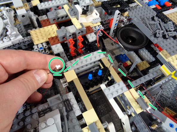
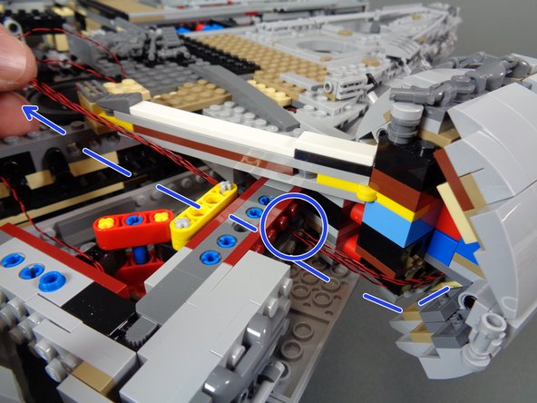
As shown by the green circle in the second photo, you should have one end of the 24" connecting cable ready to route towards the back of the Falcon.
-
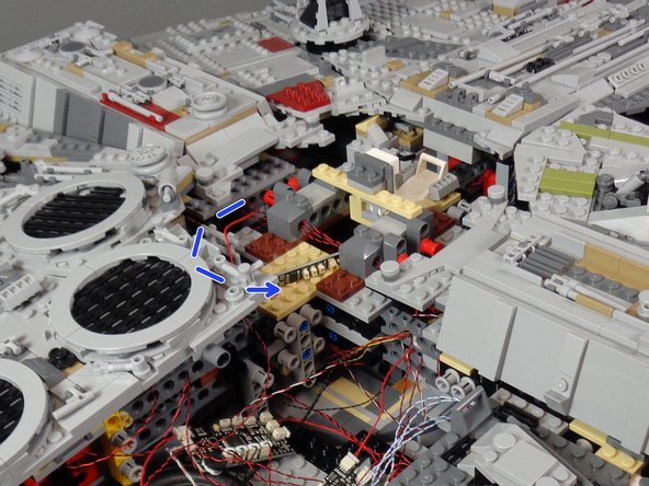
As shown by the blue dotted lines and blue circle in the third photo, carefully run the 24" connecting cable from the right docking bay area, through the center of the Falcon, and back into the rear space near the "laser" sound module speaker and TRUNK08 master controller.
-
-
-
As shown in the photos for this step, connect the landing lights to the OUT4 connector on your TRUNK08 master controller.
-
The photos show the two different versions of TRUNK08 master controller that could be included with your kit. Refer to the photo that matches the TRUNK08 you received with your kit.
-
Make sure you connect the landing lights to the OUT4 output on the TRUNK08 master controller. This will leave the OUT3 plug on the TRUNK08 empty for now. Later, you will connect the Hyperdrive unit to the OUT3 plug.
-
If you purchased the exterior-only light kit, you can skip to Step 41.
-
-
-
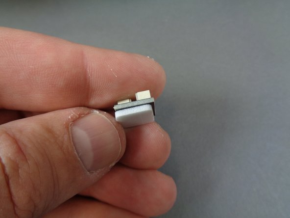
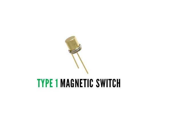
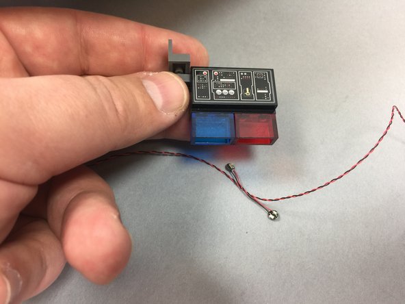
Depending on when your Falcon kit was made, you will have one of two types of magnetic switch included for your Falcon's boarding ramp. Each type of switch has a different set of installation steps-- check the photos for this step to determine which type of switch you have.
-
"Type 1" magnetic switch has a gold can-shaped part glued to a 1x4 LEGO tile.
-
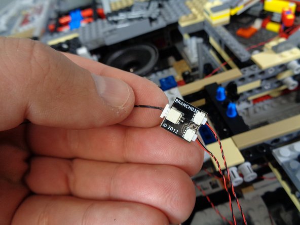
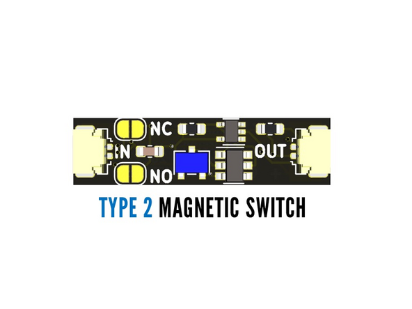
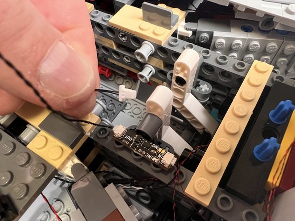
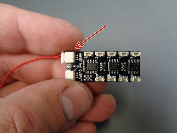
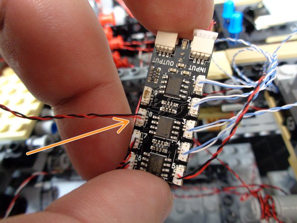
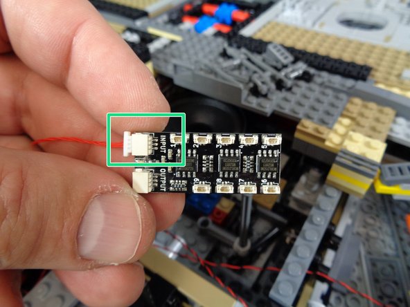
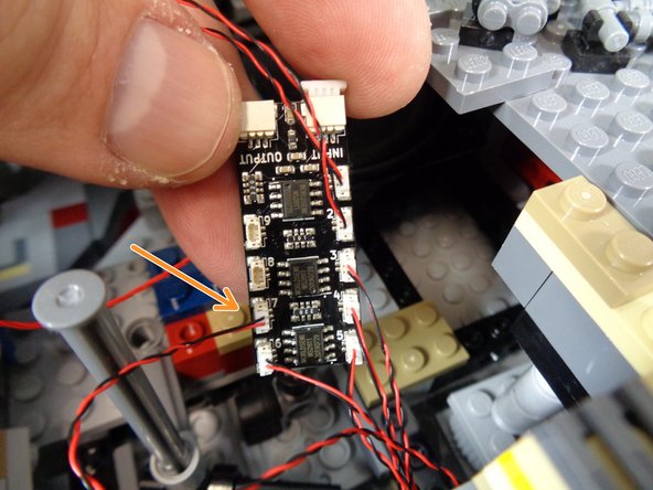
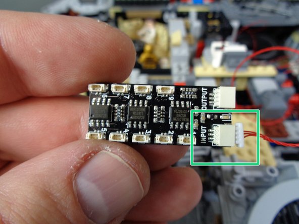
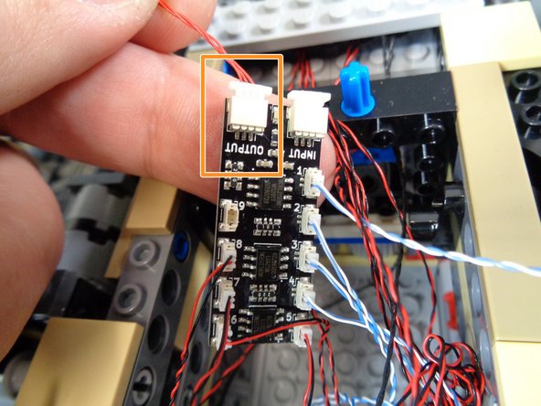
"Type 2" magnetic switch is a small circuit board with two plugs (one marked "IN" and one marked "OUT".
-
If you have a Type 1 magnetic switch, proceed to the next step. If you have a Type 2 magnetic switch, proceed to Step 34.
-
-
-
If you purchased the exterior-only light kit, you can skip to Step 41.
-
NOTE: these steps apply only to kits with a Type 1 magnetic switch included (see the previous step for the two types of switches). If you have a Type 2 magnetic switch in your kit, jump to Step 34.
-
Your kit includes a magnetic switch that controls a light inside the boarding ramp. The light turns on when the boarding ramp is open and it turns off when the ramp is closed.
-
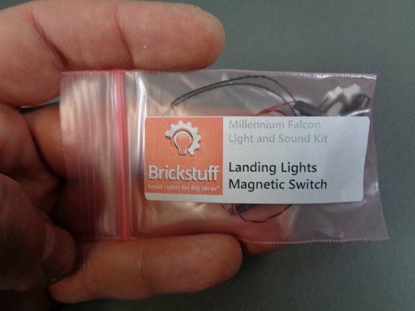
The parts for the magnetic switch are included in the pink bag labeled Landing Lights Magnetic Switch.
-
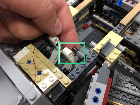
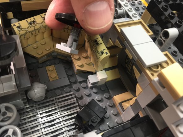
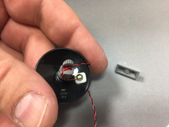
Remove the magnetic switch and black Technic pin from the Landing Lights Magnetic Switch bag.
-
As shown by the green rectangle in the second photo, carefully detatch the white Technic arm from its pin.
-
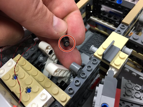
As shown in the third photo, remove the black Technic pin and replace with the pin included with your Brickstuff kit.
-
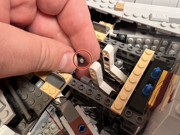
The Technic pin supplied with your kit has a small magnet mounted inside (see the red circle in the third photo). Make sure to mount the pin with the magnet facing OUT, toward the front of the Falcon.
-
-
-
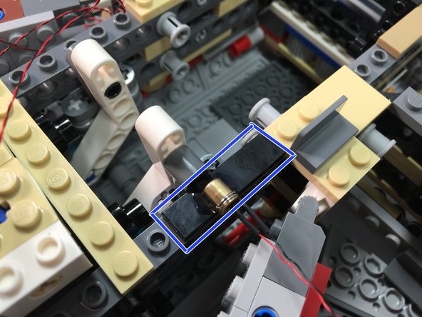
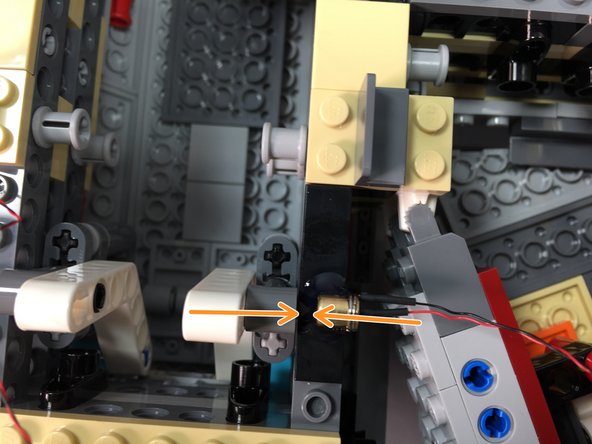
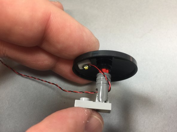
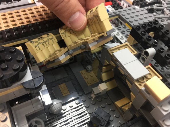
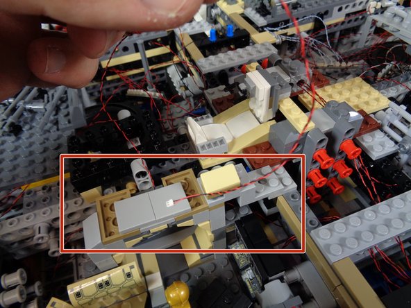
Re-attach the white Technic arm, and close the boarding ramp. Make sure the ramp closes with the magnet facing the outside of the frame as shown by the green arrow in the first photo.
-
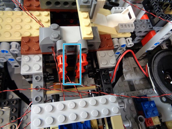
Attach the magnetic switch assembly as shown by the blue rectangle in the second photo.
-
Make sure the magnetic switch aligns with the magnet inside the black Technic pin.
-
As shown by the two orange arrows in the third photo, when the boarding ramp is closed, the magnetic switch and the magnet inside the black Technic pin should align.
-
Try opening and closing the boarding ramp several times. If you listen closely, you should hear a soft "click" when the ramp opens and closes-- this is the magnet switch turning on and off in response to the moving magnet inside the black Technic pin.
-
-
-
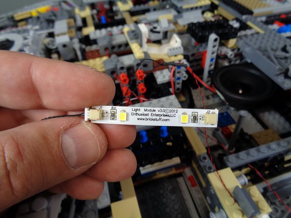
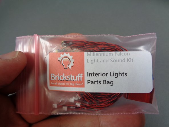
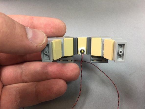
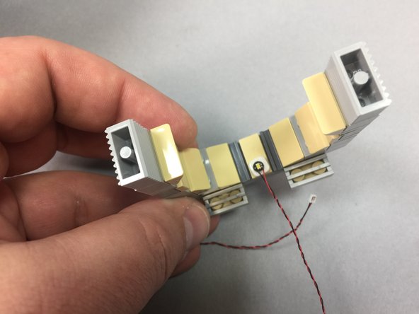
Remove the cool white light strip and 2x4 LEGO plate from inside the Landing Lights Parts Bag.
-
The color of the 2x4 LEGO plate included with your kit may differ from the one shown in these photos.
-
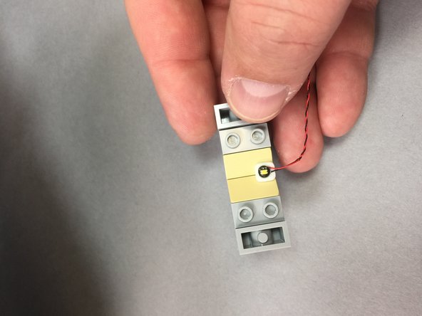
As shown in the first photo, connect one plug from the magnetic connector assembly to one end of the cool white light strip.
-
You can connect the plug to either end of the light strip.
-
Note that the color of the wire may be different than the wire shown in the photo-- you may have black wires or red/black wires. Also, your wires may be thicker than the wires shown in the photo. That is ok.
-
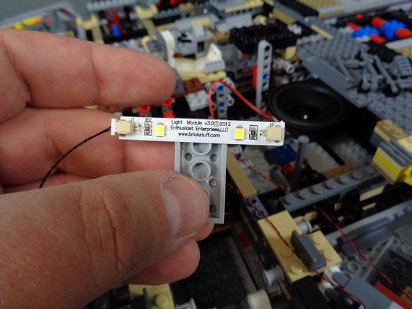
As shown in the second photo, remove the self-adhesive backing from the light strip and stick it to the edge of the 2x4 LEGO plate.
-
The second photo shows the 2x4 plate attached to the center of the light strip. You will actually need to mount the 2x4 plate so it is off-center as shown in the third photo. This is to allow clearance for the boarding ramp.
-
As shown in the third photo, attach the 2x4 plate to the side of the boarding ramp wall. Make sure there is enough clearance for the boarding ramp to open and close without hitting either the light strip or its cable.
-
-
-
As shown by the dotted green line and green circle in the first photo, run the other end of the magnetic switch wire behind the boarding ramp area and back toward the location of the TRUNK08 master controller.
-
As shown in the second and third photos, connect the magnetic switch power plug to one of the three power input/output plugs on the TRUNK08 master controller.
-
Note that the color of the magnetic switch wire may be different than the wire shown in the photo-- you may have black wires or red/black wires. Also, your wires may be thicker than the wires shown in the photo. That is ok.
-
All three of the power input/output plugs on the TRUNK08 master controller are electrically connected, so it does not matter which of the three plugs you use for the magnetic switch.
-
Note that the second and third photos show the two different versions of TRUNK08 master controller that might be included with your kit. Refer to the photo that matches the design/version of TRUNK08 included with your kit.
-
Installation of your Type 1 magnetic switch is complete. You can move forward to Step 38 to continue installation.
-
-
-
If you purchased the exterior-only light kit, you can skip to Step 41.
-
NOTE: these steps apply only to kits with a Type 2 magnetic switch included (see Step 29 for the two types of switches). If you have a Type 1 magnetic switch in your kit, return to Step 30.
-
Your kit includes a magnetic switch that controls a light inside the boarding ramp. The light turns on when the boarding ramp is open and it turns off when the ramp is closed.
-
The parts for the magnetic switch are included in the pink bag labeled Landing Lights Magnetic Switch.
-
Remove the magnetic switch and black Technic pin from the Landing Lights Magnetic Switch bag.
-
As shown by the green rectangle in the second photo, carefully detatch the white Technic arm from its pin.
-
As shown in the third photo, remove the black Technic pin and replace with the pin included with your Brickstuff kit.
-
The Technic pin supplied with your kit has a small magnet mounted inside (see the red circle in the third photo). Make sure to mount the pin with the magnet facing OUT, toward the back of the Falcon.
-
-
-
Re-attach the white Technic arm, and close the boarding ramp. Make sure the ramp closes with the magnet facing the outside of the frame as shown by the green arrow in the first photo.
-
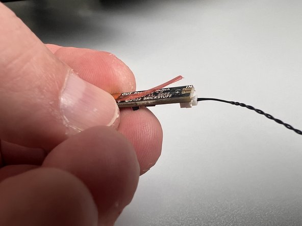
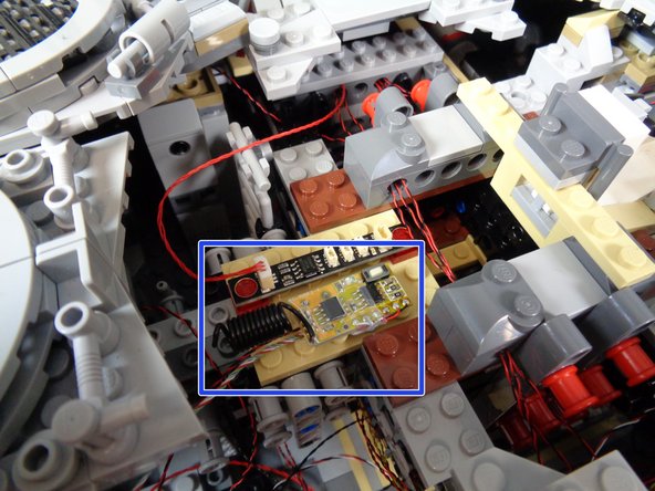
There is a thin adhesive film on the back side of the magnetic switch circuit board. Carefully remove the red strip covering the adhesive, as shown in the second photo.
-
This next step is critical to ensuring proper operation of your boarding ramp light.
-
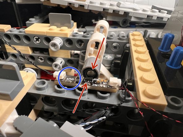
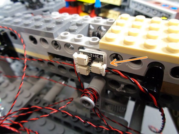
Carefully attach the magnetic switch circuit board to the frame of your Falcon exactly as shown in the third photo, with the side of the board labeled "OUT" facing inward toward the center of your Falcon (as shown by the blue circle).
-
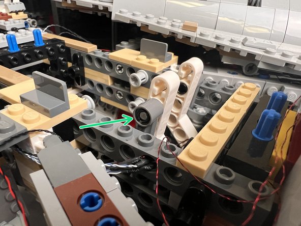
As shown by the two red arrows in the third photo, make sure the small black part on the circuit board is aligned directly next to the magnet inside the Technic pin. The small black part is the magnetic switch, and it needs to be as close to the magnet inside the Technic pin as possible.
-
Make sure the board is attached with the "OUT" side facing toward the center of your Falcon and the "IN" side facing toward the outside of your Falcon. The switch needs to be mounted this way in order for the wires to reach their connections.
-
-
-
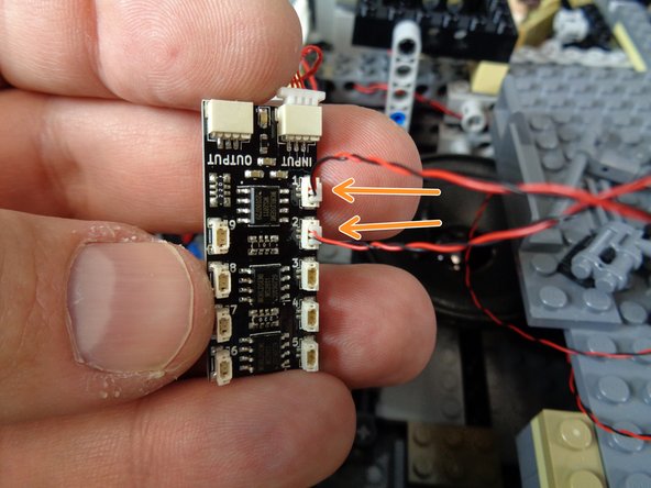
There should be a wire connected to the "OUT" plug on the magnetic switch circuit board (see the first photo for this step).
-
Remove the cool white light strip and 2x4 LEGO plate from inside the Landing Lights Parts Bag.
-
As shown in the second photo, connect the wire from the "OUT" plug on the magnetic switch circuit board to one of the plugs on the cool white light strip.
-
Also as shown in the second photo, remove the self-adhesive backing from the light strip and stick it to the edge of the 2x4 LEGO plate.
-
As shown in the third photo, attach the 2x4 plate to the side of the boarding ramp wall. Make sure there is enough clearance for the boarding ramp to open and close without hitting either the light strip or its cable.
-
The green arrows in the third photo show how the light strip wire should be routed, to keep it away from the blue Technic pins or any other part of the Falcon frame that could catch, pinch, or cut the wire.
-
-
-
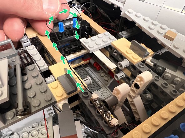
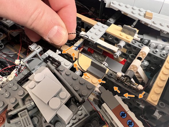
The orange arrows in the first photo for this step show how to route the wire connected to the "IN" plug on the magnetic switch circuit board.
-
Make sure to run the wire away from where the boarding ramp opens and closes, so the wire does not get caught or pinched by the moving of the ramp.
-
As shown in the first photo, the large white plug can be fed down through the Falcon frame toward the TRUNK08 master controller.
-
As shown by the purple arrow in the second and third photos, connect the magnetic switch power plug to one of the three power input/output plugs on the TRUNK08 master controller.
-
All three of the power input/output plugs on the TRUNK08 master controller are electrically connected, so it does not matter which of the three plugs you use for the magnetic switch.
-
Note that the second and third photos show the two different versions of TRUNK08 master controller that might be included with your kit. Refer to the photo that matches the design/version of TRUNK08 included with your kit.
-
-
-
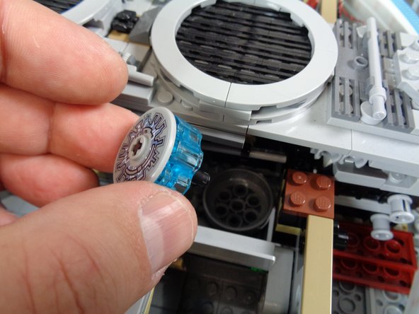
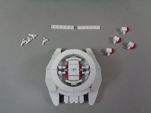
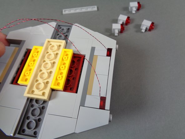
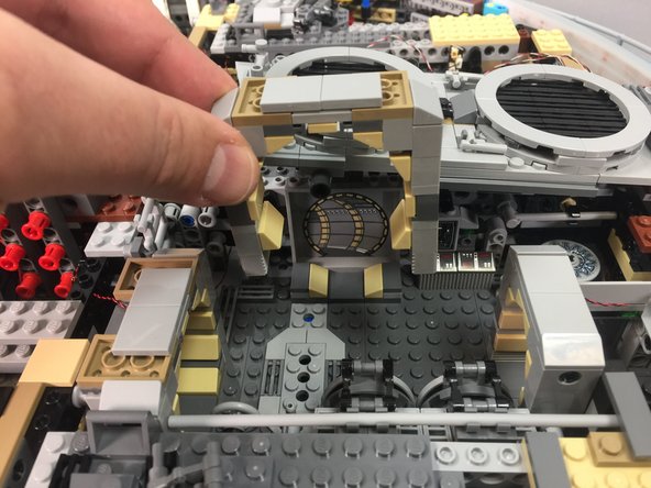
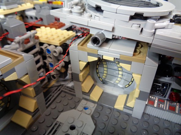
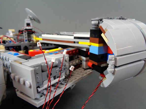
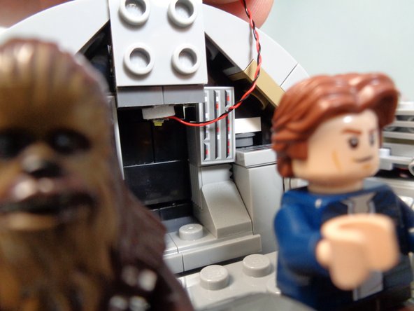
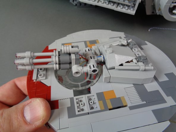
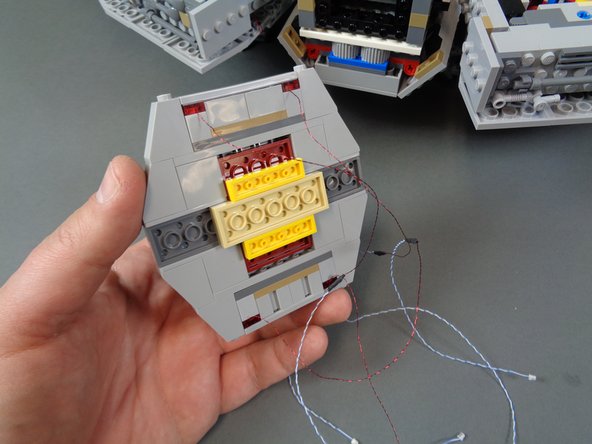
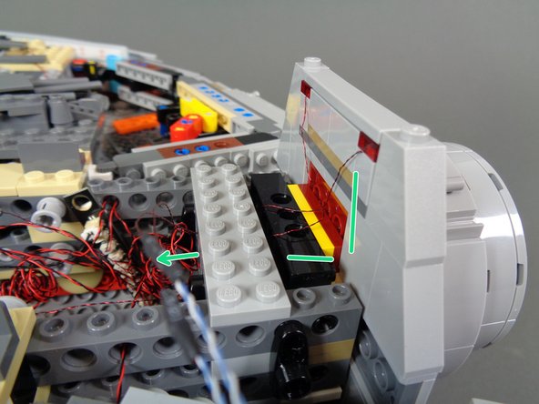
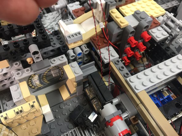
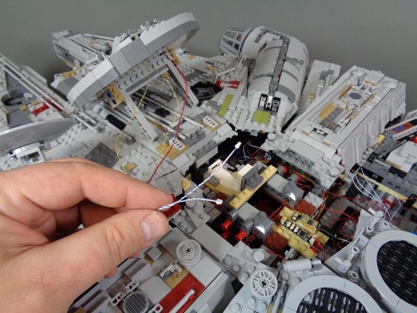
As shown in the first photo, remove the center portion of the hyperdrive in the back of the Falcon.
-
Make sure to remove the top disc, transparent blue center, and center Technic axle.
-
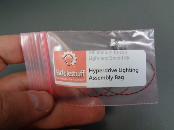
Remove the hyperdrive assembly from its bag (the hyperdrive assembly bag is inside the larger bag labeled Interior Lighting Kit).
-
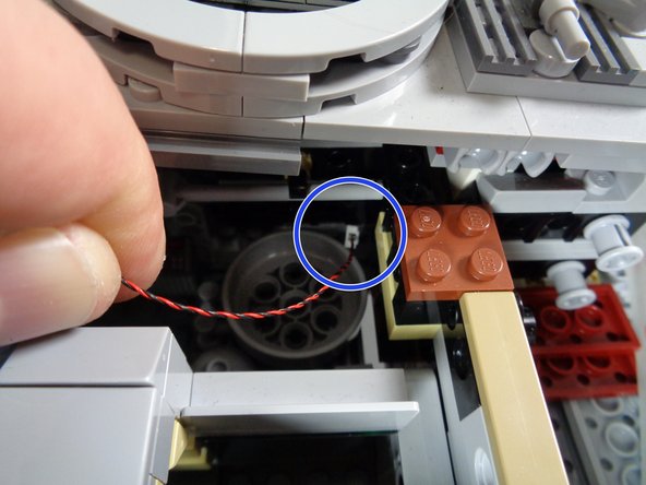
As shown by the blue circle in the third photo, feed the hyperdrive unit power cable under the center rear section of the Falcon, so the wire comes out in the right rear section (close to the TRUNK08 master controller).
-
-
-
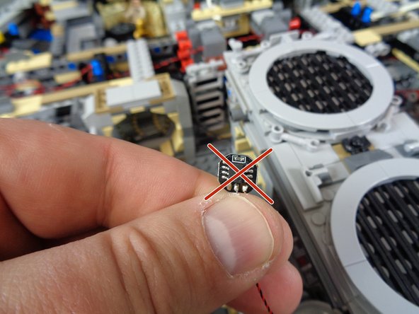
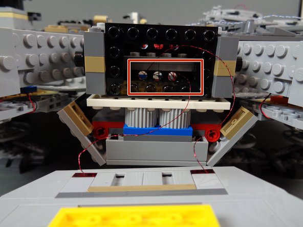
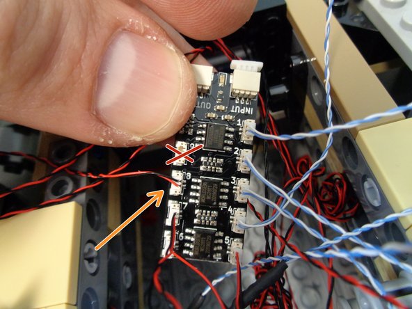
The hyperdrive unit has a top and bottom. The bottom is shown in the first photo with the red "X"-- this side has a black chip in the center. Do not install with this part facing up.
-
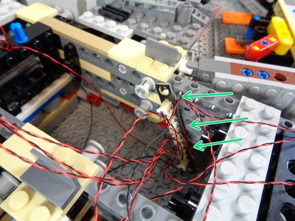
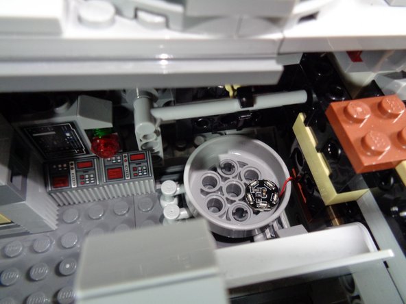
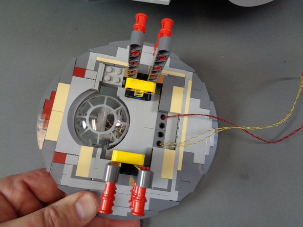
As shown in the second photo, install the hyperdrive with the five little lights facing upward, and place the hyperdrive unit in the center rear of the Technic hub.
-
Bend the hyperdrive power wires as shown in the second photo, so the hyperdrive unit sits flat inside the Technic hub.
-
Make sure the center hole in the Technic hub is not blocked. This hole needs to be open in order for the top of the hyperdrive to be re-attached.
-
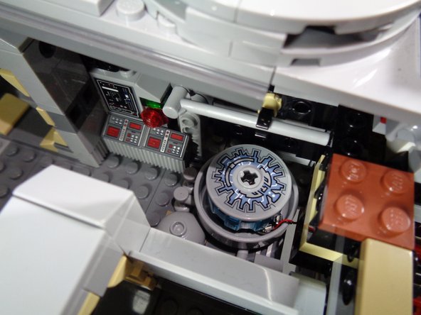
As shown in the third photo, re-attach the top of the hyperdrive. No wires should be pinched.
-
-
-
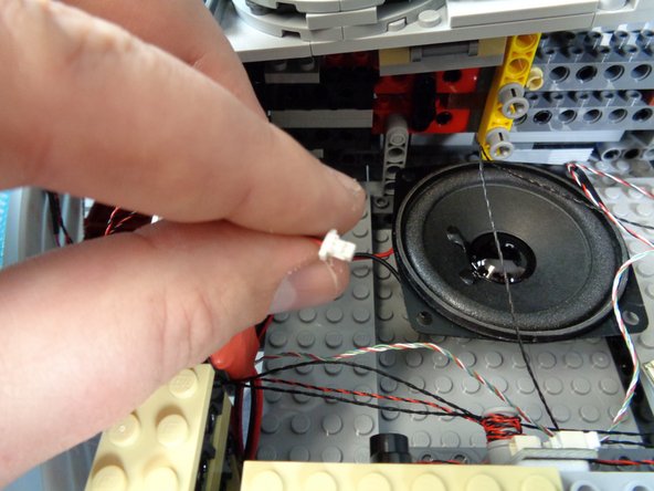
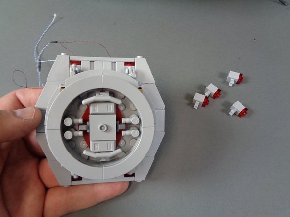
As shown in the first photo, you should have the hyperdrive power plug in the right rear section of the Falcon.
-
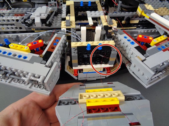
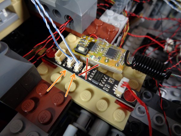
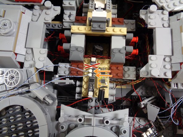
As shown in the second and third photos, connect the hyperdrive power plug to the OUT3 connector on the TRUNK08 master controller.
-
The second and third photos show the two different styles of TRUNK08 controller that may be included with your kit. Refer to the photo that matches the TRUNK08 design included with your kit.
-
-
-
For all of the rest of the lights in your Falcon kit, you will connect them in a single chain using adapter boards with only one connection to the main TRUNK08 master controller.
-
In order for the lights and effects to work as designed, it is essential that you connect them exactly as shown in the following steps. Lights must be connected to the exact adapter and plug number shown.
-
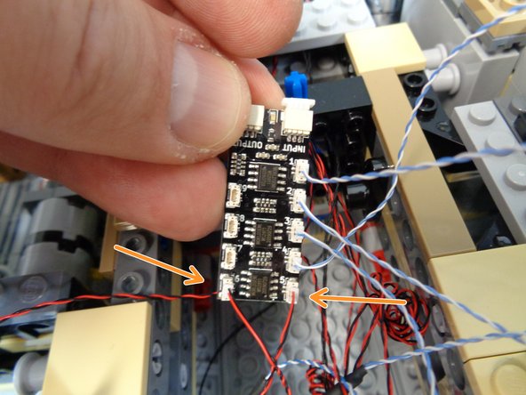
Remove one of the BRANCH09X adapter boards and one of the red 12" 3-wire connecting cables from the Main Control and Connecting Parts bag.
-
You have several types of adapter boards in the Main Control and Connecting Parts bag. For this step, you need the BRANCH09X board, which has nine small plugs and two large plugs. You also have a BRANCH09 adapter board, which only has three small plugs. Do not use the BRANCH09 board yet.
-
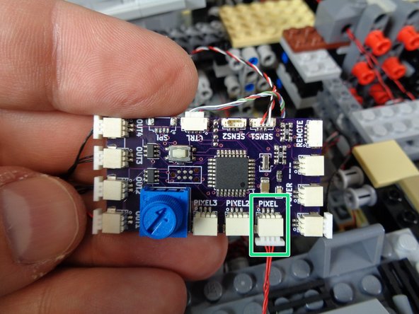
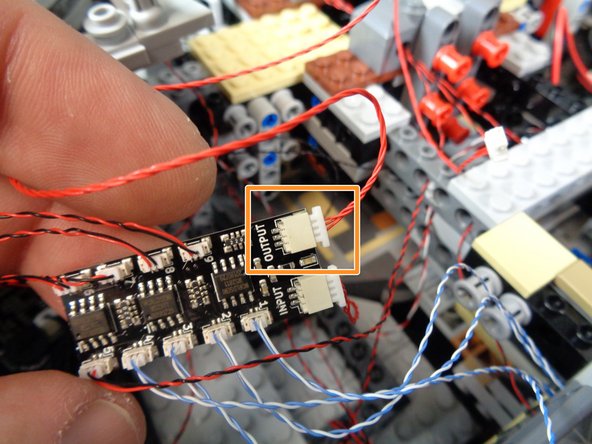
As shown by the red arrow in the first photo, connect one end of the red 3-wire cable to the INPUT plug on the BRANCH09X adapter. DO NOT connect the plug to the OUTPUT connector.
-
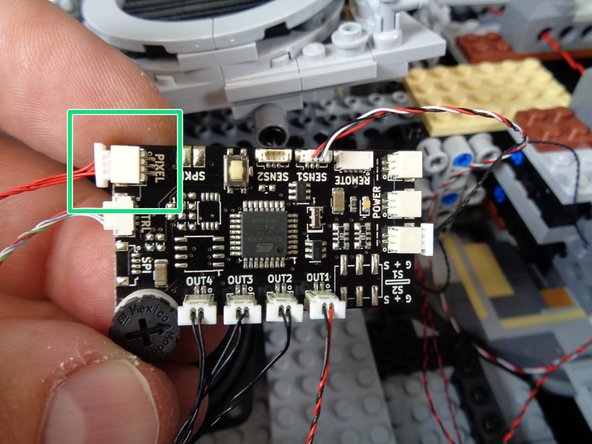
As shown by the green rectangles in the second and third photos, connect the other end of the red cable to the PIXEL plug on the TRUNK08 master controller.
-
The second and third photos show the two different designs of TRUNK08 master controller that may be included with your kit. Refer to the photo that matches the TRUNK08 design you received.
-
If your TRUNK08 master controller looks like the controller in the third photo, you will have a plug mounted only at the location labeled "PIXEL." The other two "PIXEL" plugs will be unpopulated (not mounted on the circuit board). The photo here shows all three plugs mounted, but you will only have one mounted.
-
-
-
As shown in the photos for this step, open the box labeled LED Lighting Assemblies.
-
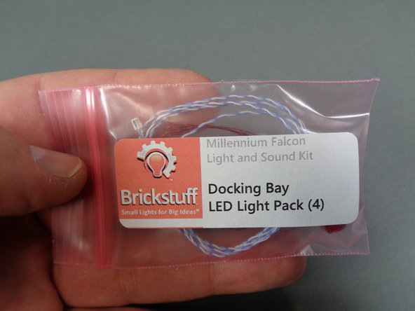
Inside the box, there will be two bags labeled Docking Bay LED Light Pack (4).
-
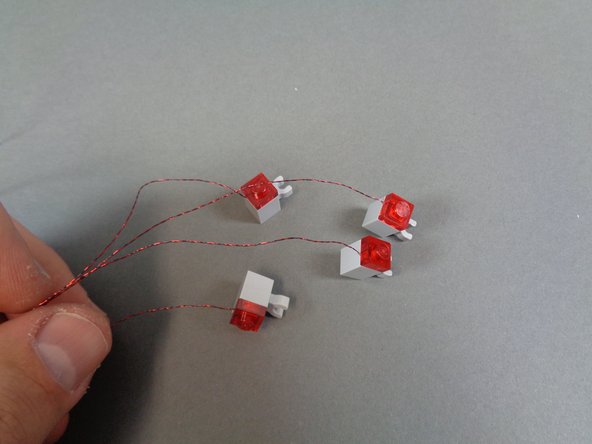
Open one of the bags and carefully remove the four pre-mounted docking bay lights.
-
The thin wires on the docking bay lights can easily become tangled. Before proceeding, make sure the wires are not tangled.
-
The wires for your docking bay lights may be different thicknesses or colors than the ones shown in the photos here. That is ok.
-
-
-
As shown in the photos for this step, carefully remove the top and bottom center parts from the docking bay cap.
-
Replace with the four pre-assembled lights included in your kit.
-
Re-attach the other docking bay parts.
-
As shown in the third photo, the wires for each of the four lights should extend out the back of the docking bay cap.
-
Make sure none of the wires are tangled.
-
-
-
Now you will re-attach the right docking bay cap.
-
When re-attaching the cap, it is important to make sure that none of the light wires become pinched.
-
As shown by the red circles in the first and second photos, pass the wires from the two bottom lights through the Technic stud holes in the bricks at the end of the docking bay. Also pass the wires through the dark bluish gray Technic brick at the side of the docking bay wall.
-
Make sure the wires do not interfere with the opening and closing of the boarding ramp. The lights can become damaged if the boarding ramp catches on or pulls any of the light wires.
-
-
-
Re-attach the docking bay cap, making sure to pull the bottom light wires fully through the Technic bricks so the bottom light wires don't get pinched when the cap is re-attached.
-
As shown in the first photo, remove the tan 1x8 plate at the end of the docking bay wall and carefully run the top light wires between the studs.
-
As shown by the orange arrows in the first photo, make sure the top light wires run flat down the back of the docking bay cap and that there is extra slack in the wires so they do not become pinched or cut when the top of the docking bay is re-attached at the end of the assembly process.
-
As shown in the second photo, re-attach the tan 1x8 plate. Make sure the light wires run between, not on top of, any studs under the plate.
-
As shown by the red circle in the third photo, pass the ends of the top light wires through the same hole in the dark bluish gray Technic brick as the bottom light wires.
-
You should now have four wires pulled into the right rear section of the Falcon, close to the TRUNK08 master controller.
-
-
-
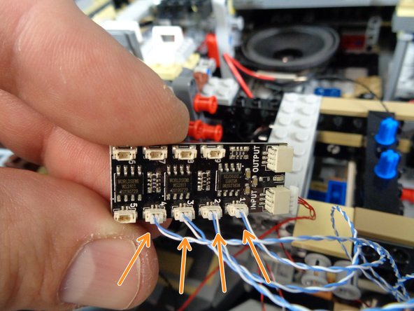
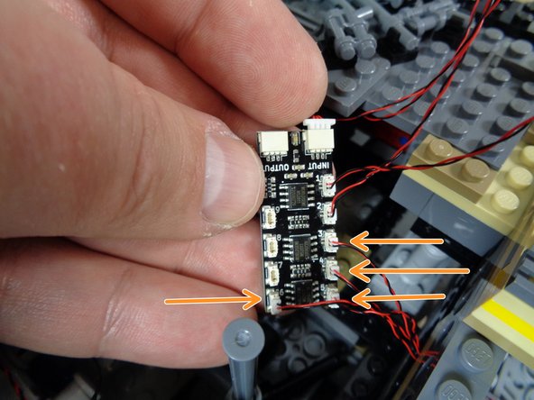
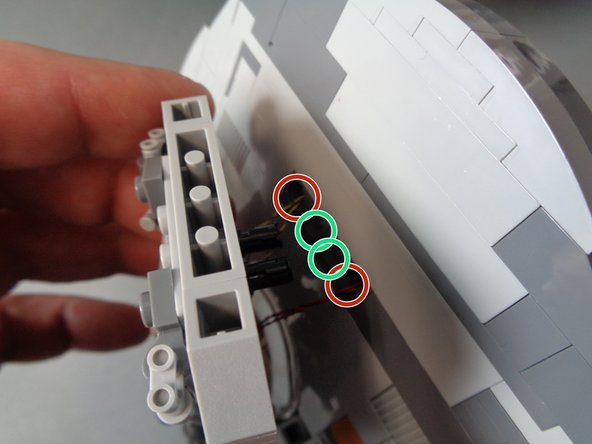
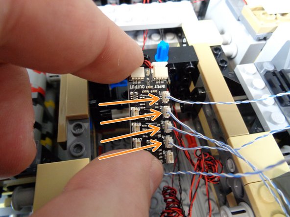
As shown by the four orange arrows in the photo for this step, connect the four docking bay lights to plugs #1, #2, #3, and #4 on the BRANCH09X adapter board.
-
For the lights to operate correctly, it is critical that you connect the lights to the exact plugs shown.
-
It does not matter which light connects to which plug. All four lights operate under the same lighting effect. Just make sure to connect the four lights to plugs 1-4 on the BRANCH09X adapter board.
-
If you did not purchase interior lights with your kit, you can skip to Step 55.
-
-
-
Inside the bag labeled Interior Lighting Kit is a smaller bag labeled Interior Lights Parts Bag. Inside that smaller bag are 10 cool white Pico LEDs.
-
Begin installing the rear interior lights by removing the top door frame from the rear interior room as shown in the third photo.
-
-
-
As shown in the first photo, take a small sticky square from the Main Control and Connecting Parts bag and use it to attach one LED light to the top of the door frame you removed in the previous step.
-
As shown in the first photo, attach the light to the rear part of the door frame. The light should sit at the back of the frame.
-
As shown by the red circle in the second photo, re-attach the door frame top so the LED light is at the back of the frame and the light wire extends out the back of the frame.
-
As shown by the blue dotted line in the third photo, route the LED light wire through the center of the Falcon and into the right rear space, close to the BRANCH09X adapter board.
-
-
-
As shown in the photos in this step, remove the top of the rear door frame, attach another LED light to the top rear of the door frame using another small sticky square, then re-attach the door frame.
-
As shown by the red circle in the third photo, route the light wire towards the back of the Falcon and hold it in place with the dark tan tile.
-
Make sure to run the wire between, not on top of, any studs under the tile.
-
Run the light wire under the rear center of the Falcon and into the right rear space near the BRANCH09X adapter board.
-
-
-
As shown in the photos for this step, remove the top of the third door frame in the rear interior space.
-
Use another small sticky square to attach a Pico LED light to the top rear of the door frame, then replace the frame.
-
Run the LED light wire into the right rear space, close to the BRANCH09X adapter board.
-
You should now have three light wires in the right rear space of the Falcon within reach of the BRANCH09X adapter board.
-
-
-
As shown by the three green arrows in the photo for this step, connect the three door frame lights to plugs #5, #6, and #7 on the BRANCH09X adapter board.
-
It does not matter which specific plug you connect each door frame light to, as long as you only use plugs #5-7 on the BRANCH09X adapter board.
-
-
-
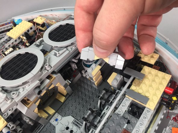
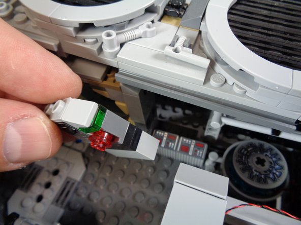
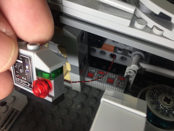
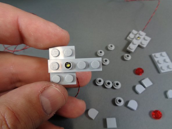
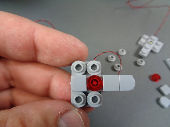
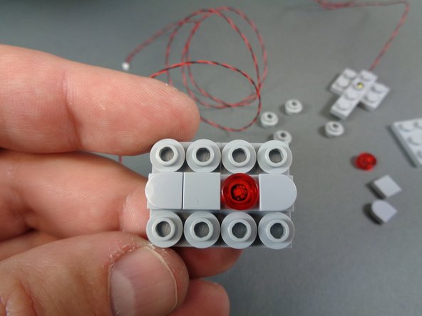
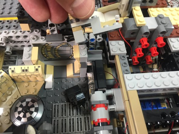
As shown in the photos for this step, remove the control panel from the interior area near the hyperdrive and mount a Pico LED light through the hole in the dark bluish gray brick.
-
The photos here show a round transparent red plate on the control panel-- your Falcon will not have this, as the original LEGO kit does not include it. The piece is included with your Brickstuff kit, in the same bag as the interior LED lights.
-
Place the transparent red round LEGO plate on top of the Pico LED, feed the LED light wire under the center section of the Falcon, then re-attach the panel as shown in the third photo.
-
-
-
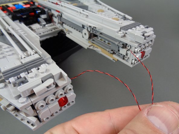
As shown in the photo for this step, connect the control panel light to the #8 plug on the BRANCH09X adapter board.
-
-
-
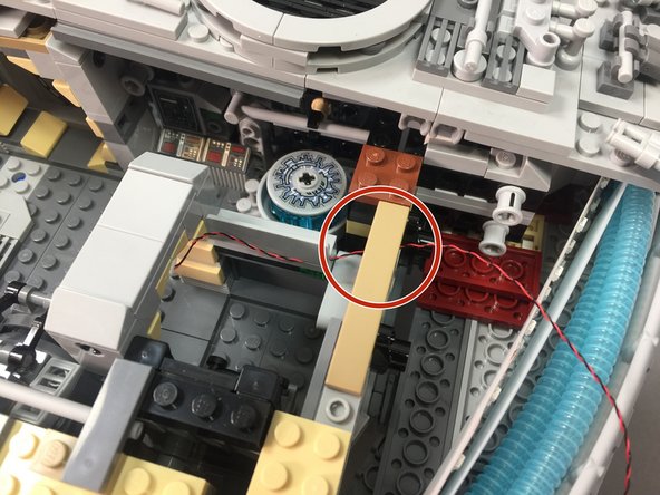
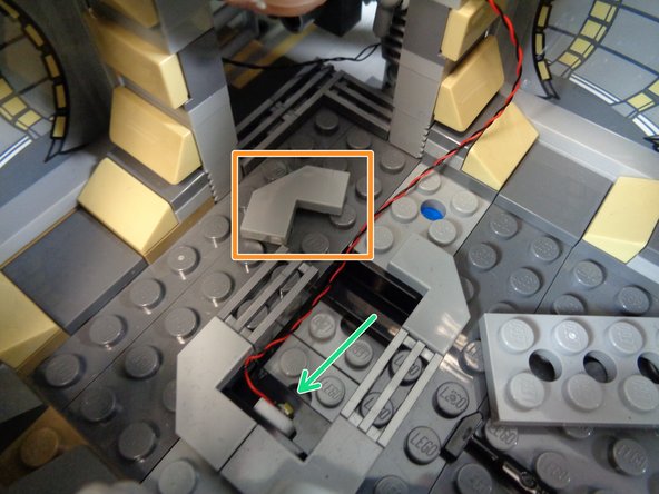
If you want to mount a light under the rear interior room floor grille, you can remove the 2x4 LEGO plate from the floor, remove the corner tile (orange rectangle in the first photo), and use a small sticky square to mount the light inside the opening as shown by the green arrow in the first photo.
-
Mount the light as low as possible inside the opening, to allow for the top 2x4 plate to fit back on top of the opening.
-
As shown in the second photo, re-attach the corner tile and run the light wire underneath the door frame and into the right rear area near the BRANCH09X adapter board.
-
You will need to lift up the door frame again to pass the wire underneath.
-
As shown by the orange arrow in the third photo, connect the underfloor light to the #9 plug on the BRANCH09X adapter board.
-
This should be the last open small plug on the adapter board. All small plugs on the BRANCH09X adapter board should now be filled.
-
-
-
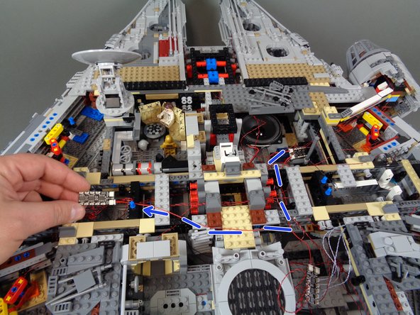
Now you will connect the next BRANCH09X adapter board in the lighting control chain.
-
Take another 12" red 3-wire cable from the Main Control and Connecting Parts bag, along with another BRANCH09X adapter board.
-
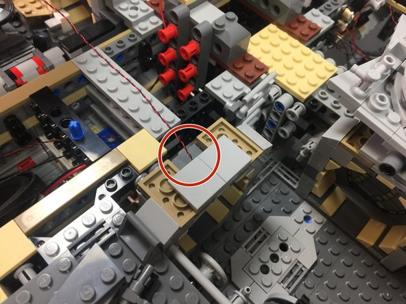
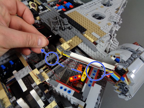
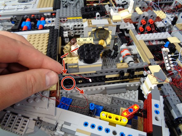
As shown by the orange rectangle in the first photo, connect one end of the red cable to the OUTPUT plug on the first BRANCH09X adapter board (the one with all nine small plugs filled).
-
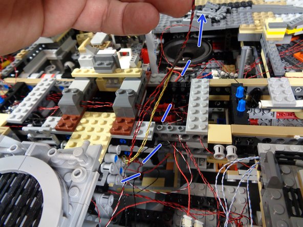
As shown by the blue dotted line, arrow, and circle in the second photo, carefully route the red wire between the Technic bricks in the Falcon frame so the wire reaches into the front right area near the "engines" speaker.
-
As shown by the green arrow in the third photo, connect the red wire to the INPUT plug on the second BRANCH09X adapter board.
-
For the lights to operate properly, it is critical that you connect INPUTs and OUTPUTs correctly, The green power light on the BRANCH09X adapter boards will come on even if INPUTs and OUTPUTs are reversed, but connected lights will not work.
-
-
-
Next, you will attach the pre-lit mandibles and connect them.
-
As shown in the first photo, remove the front mandibles from your Falcon.
-
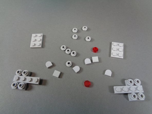
As shown in the second photo, disassemble the mandible parts.
-
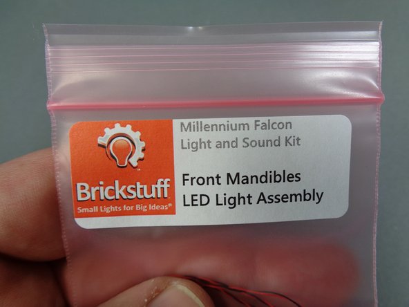
As shown in the third photo, take the bag labeled Front Mandibles LED Light Assembly out of the box labeled LED Lighting Assemblies.
-
-
-
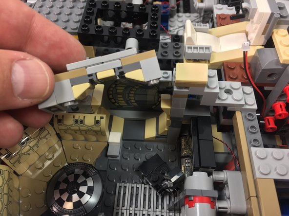
Take the two mabdible assemblies out of the bag, and begin re-attaching parts to the new assembly as shown in the photos for this step.
-
Repeat for the second mandible assembly.
-
The mandibles bag also includes two round clear LEGO tiles. You can use these instead of the transparent red tiles that came with your original kit to model different versions of the Falcon.
-
-
-
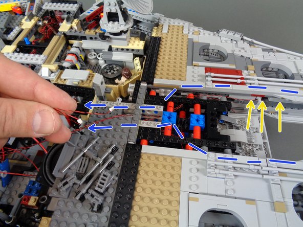
As shown in the first photo, re-attach the two front mandibles.
-
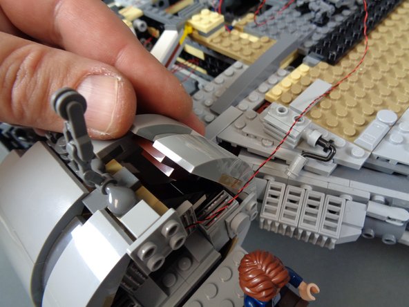
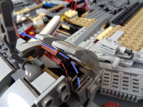
As shown by the blue dotted lines and arrows in the second photo, carefully route the mabdible light wires down the inner sides of the Falcon and back toward the second BRANCH09X adapter board.
-
As shown by the yellow arrows in the second photo, you can gently pry up the tops of the mandibles to make room to run the wires inside.
-
As shown by the orange arrows in the third photo, connect the two mandible lights to plugs #1 and #2 on the second BRANCH09X adapter board.
-
It does not matter which mandible light you connect to plug #1 and #2, since they both use the same effect.
-
-
-
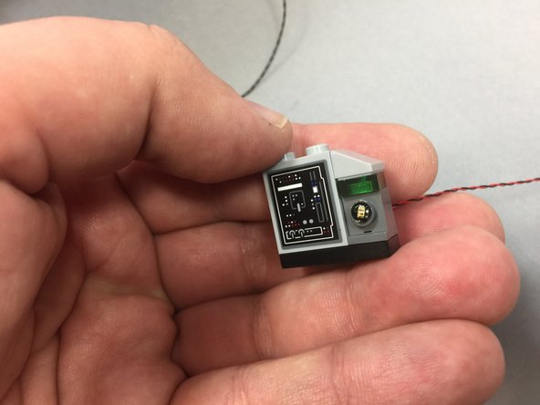
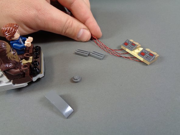
Next, you will install the modified cockpit control panel with four pre-installed lights that came with your Brickstuff kit.
-
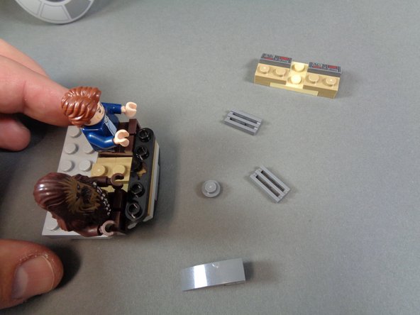
As shown in the first photo, remove the cockpit windshields and front section.
-
Remove the parts as shown in the second photo.
-
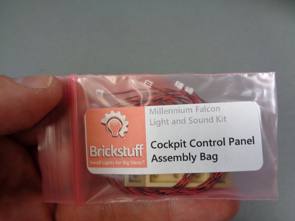
Remove the modified cockpit control panel from the Cockpit Control Panel Assembly Bag (which is located inside the larger bag labeled Interior Lighting Kit).
-
-
-
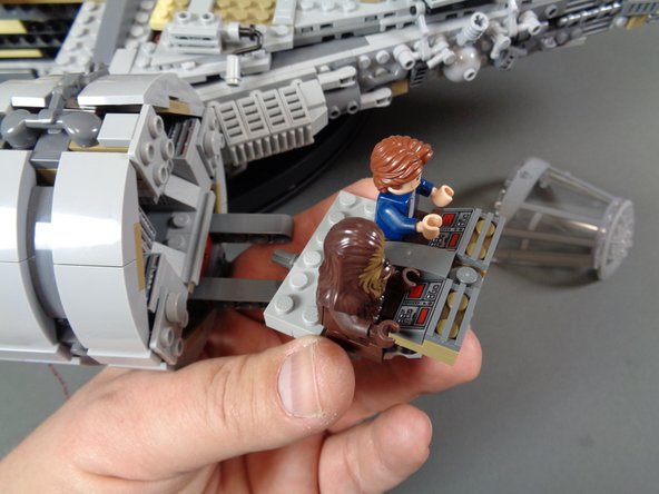
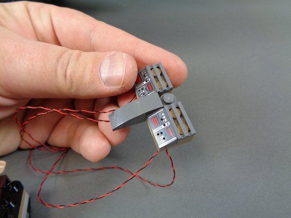
As shown in the photos for this step, mount the modified cockpit control panel inside the cockpit and replace the smaller parts you removed in the last step.
-
After re-assembly, your cockpit section should look like the cockpit in the third photo (although, maybe not with the minifigures!).
-
-
-
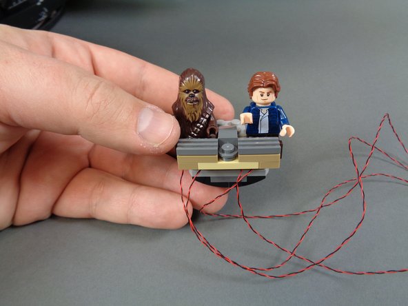
As shown in the photos for this step, run the four cockpit control panel wires under the cockpit and back through the open area toward the back of the cockpit passage.
-
As shown by the blue dotted lines and circle in the third photo, feed the four cockpit control panel wires through a hole in the Technic brick in the Falcon frame, and into the open space near the "engines" speaker.
-
-
-
As shown by the orange arrows in the photo for this step, connect the four cockpit control panel light wires to plugs #3, #4, #5, and #6 on the second BRANCH09X adapter board.
-
It does not matter which specific light you connect to a specific plug, as long as you use only plugs # 3-6 on the BRANCH09X adapter board.
-
-
-
Take a Pico LED light and small sticky square, and mount the light to the center back of the cockpit door as shown in the first photo.
-
As shown in the second and third photos, lift up the top sections of the cockpit passage and feed the light wire through the opening toward the back of the cockpit.
-
The dotted blue line in the third photos shows the direction the light wire should run.
-
-
-
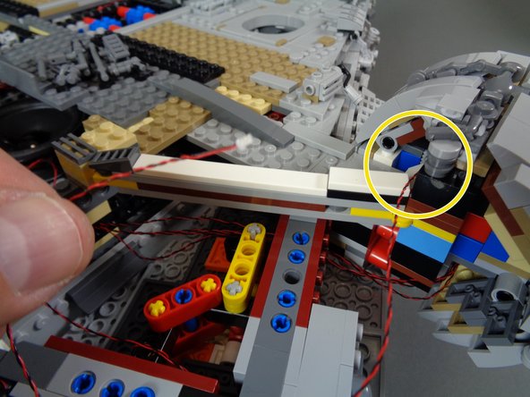
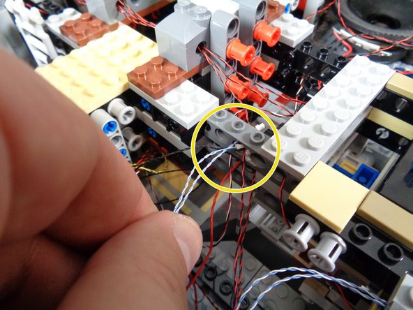
As shown by the yellow circle in the first photo, the cockpit light wire should pass out the back of the top corridor section.
-
Route the light wire as shown by the dotted blue lines in the second photo. The two blue circles show where the wire should pass through stud holes in the Falcon frame bricks.
-
As shown by the orange arrow in the third photo, connect the cockpit light to plug #7 on the second BRANCH09X adapter board.
-
-
-
Note that your Falcon kit includes only one laser cannon. You have the option to purchase a second cannon if desired. Please contact us through the contact form on our website if you would like a second cannon.
-
If you want to order a second cannon and do not have one now, you can just install the top cannon (included with your Brickstuff kit) as the bottom cannon, then easily install the top cannon later when your second cannon arrives.
-
The next section applies only to those who have purchased the lower laser cannon-add on kit. If you do not have this kit, or if you choose not to install the lower laser cannon, you can skip to Step 72.
-
As shown by the orange arrows in the first photo, place your Falcon on a flat surface where you can reach the underside. Gently pull the entire lower laser cannon assembly off the main Falcon frame.
-
As shown in the second photo, remove the pieces that hold the laser cannon to the turret.
-
Remove the pre-lit laser cannon from its bag as shown in the third photo.
-
-
-
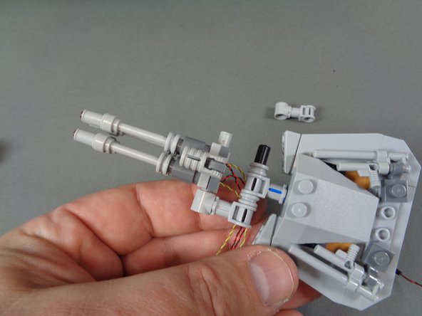
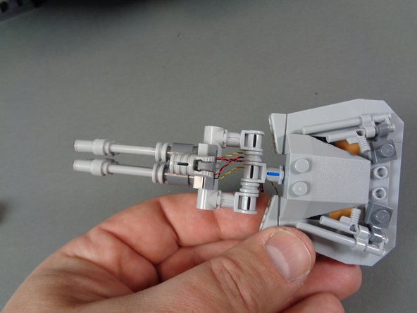
As shown in the photos for this step, mount the pre-lit laser cannon so its wires pass to the lower side of the turret.
-
Your laser cannon may have different color wires, different length wires, or wires of different thicknesses than those shown in these photos.
-
-
-
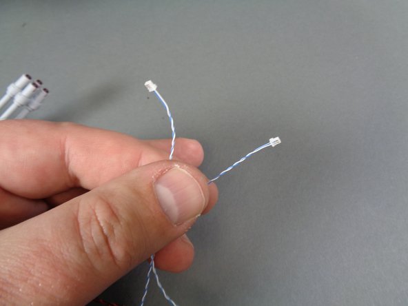
The laser cannon in your kit will have one of two different types of connectors. The first photo shows the first type of connector-- these are small Pico connectors with blue and white wires.
-
If your laser cannon has this type of connector, you can skip to the next step.
-
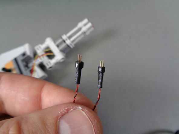
The second photo shows the second type of connector-- this connector has small metal pins. If your laser cannon has this type of connector, there should also be two adapter cables included in the same bag as the laser cannon.
-
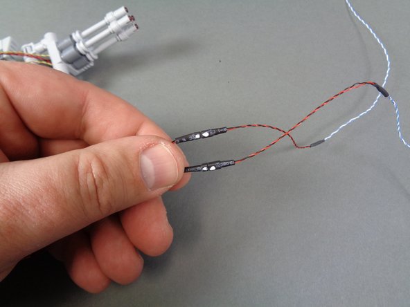
As shown in the third photo, connect the two adapter cables to the laser cannon wires so that the white dots on the connectors are aligned as shown.
-
-
-
next you will remove the lower laser mount from the underside of the Falcon.
-
Complete these steps carefully. You may need to gently lift your Falcon to allow removal of the laser mount. It maybe easier to ask someone to help lift your Falcon while you gently remove the mount.
-
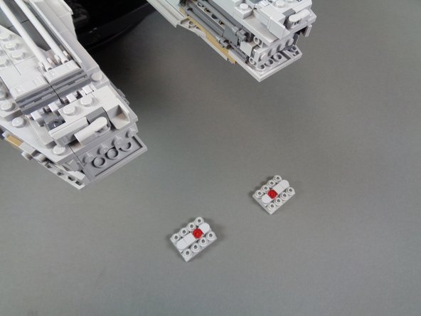
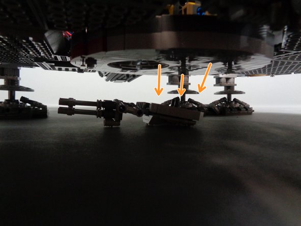
As shown in the first photo, remove the 12 red Technic pins holding the lower mount to the main Falcon frame.
-
Remove the lower mount from under the Falcon.
-
You should now have the complete lower mount removed with red pins attached, as shown in the second photo.
-
As shown by the orange rectangle in the third photo, feed the laser light wires through the two OUTER Technic holes in the mount.
-
It is important to run the wires through the OUTER holes, not the INNER holes. The laser cannon itself uses the two INNER holes to attach to the mount.
-
-
-
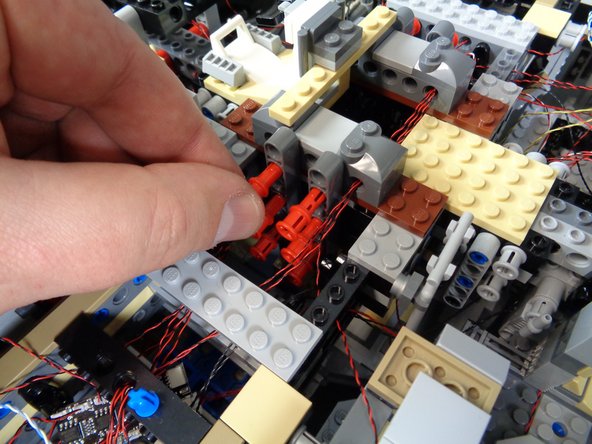
As shown in the first photo, re-attach the laser cannon to the main mount, being careful to pull the laser light wires (red circles) through the holes so there is no extra slack sticking out.
-
As shown in the second and third photos, you should now have the laser cannon re-attached to the main mount with the light wires passing through the two outer Technic holes in the mount.
-
before re-attaching the laser cannon mount to the main frame, feed the laser light wires up into the main body of the Falcon. Gently pull them as you re-attach the mount so there are no slack wires sticking out once the mount is fully re-attached.
-
-
-
Carefully re-attach the lower mount to the main frame of the Falcon as shown in the first photo. Carefully re-insert each of the 12 red Technic pins to hold the lower mount firmly in place.
-
Make sure no wires are caught under any pins when re-inserting them. If wires are caught, they can become pinched or cut.
-
As shown in the second and third photos, pull the laser light wires up through the center of the Falcon and pass the wires through the stud holes in the Technic bricks at the center of the Falcon core.
-
-
-
As shown in the photos for this step, continue routing the laser light wires up toward the second BRANCH09X adapter board.
-
As shown in the third photo, connect the two laser cannon light wires to plugs #8 and #9 on the second BRANCH09X adapter board.
-
-
-
As shown by the orange rectangle in the first photo for this step, take another red 12" 3-wire cable from the Main Control and Connecting Parts bag, and connect one end of the cable to the OUTPUT plug on the second BRANCH09X adapter board.
-
If you connected the lower laser cannon in the previous steps, you will have all nine small plugs on the BRANCH09X adapter board filled. The first photo shows plugs #8 and #9 empty-- this is ok if you did not install the lower laser cannon. You can always add it later if you want to.
-
As shown in the second photo, take the last BRANCH09X adapter board from the Main Control and Connecting Parts bag, and connect the other end of the red wire to the INPUT plug on the third BRANCH09X adapter board.
-
As shown by the blue dotted line in the third photo, route the red wire back toward the center of the Falcon, then over to the left-side docking bay area.
-
-
-
As shown in the first photo, mount the four pre-lit docking bay lights into the left-side docking bay cap. See Step 43 if you need a refresher on how to mount the lights.
-
As shown by the red rectangle in the second photo, thread the wires for the two bottom lights through the Technic stud holes in the docking bay frame.
-
Carefully re-attach the docking bay cap, making sure not to pinch any wires as you re-attach the cap to the main Falcon frame.
-
As shown by the green lines and arrow in the third photo, it is very important to allow extra slack in the wires so they sit flat against the back side of the cap. This will allow the top section to be re-attached without pinching or breaking any wires.
-
-
-
As shown by the four orange arrows in the photo for this step, connect the four docking bay lights to plugs #1, #2, #3, and #4 on the third BRANCH09X adapter board.
-
It does not matter in which order you connect specific docking bay lights, as long as you only use plugs #1-4 on the BRANCH09X adapter board.
-
If you purchased the exterior-only light kit, you can skip to Step 83.
-
-
-
Next, you will mount a light in the door frame of the front interior room. Note that these steps apply only to those who purchased a kit version that includes interior lights.
-
As shown in the photos for this step, remove the top of the front interior room door frame and attach a Pico LED light to the rear top portion of the frame using a small sticky square.
-
Set the frame and light aside for now, and do not connect yet.
-
-
-
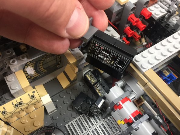
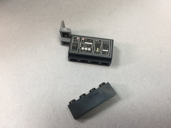
As shown in the photos for this step, remove the frame section next to the doorway, then remove the computer and its panels.
-
As shown in the third photo, remove the 1x4 black brick from the bottom of the computer panel assembly.
-
-
-
Inside the small bag labeled Interior Lights Parts, you will have one transparent blue 1x2 LEGO brick and one transparent red 1x2 brick. Use those to replace the 1x4 black brick you removed in the previous step as shown in the first photo.
-
Take two more Pico LED lights, and as shown in the second photo, insert the lights into the transparent blue and red bricks. Bend the wires so the lights extend up into the space inside the bricks, but the wires extend out the back and up the outside of the bricks.
-
As shown in the third photo, re-attach the computer, making sure the two LED lights remain inside the transparent bricks.
-
-
-
As shown by the two orange arrows in the photo for this step, connect the two computer LED lights to plugs #5 and #6 on the third BRANCH09X adapter board.
-
-
-
As shown in the photos for this step, remove the Dejarik holochess table from the front interior room, attach a Pico LED light to the underside using a small sticky square, and thread the LED light wire under the table and secure with the light bluish gray foot plate part.
-
-
-
As shown in the photos for this step, remove the seats from the front interior room, re-attach the Dejarik holochess table, and run the light wire under the seat area and out into the exterior section in front of the left docking bay.
-
The red dotted line in the third photo shows where the wire should run, after the seats have been re-installed. The light wire will run under the seats and through the stud hole in the black Technic brick as shown by the red circle.
-
The photos in this step show the top door frame attached, but you will still have your door frame detached.
-
-
-
As shown by the photo in this step, connect the table light to plug #7 on the third BRANCH09X adapter board.
-
Before connecting the wire to the BRANCH09X adapter board, make sure you have routed it through stud holes in the Technic bricks of the Falcon frame leading over to the docking bay area where the BRANCH09X adapter board is located.
-
-
-
As shown by the red rectangle in the first photo, re-attach the frame next to the interior door and the top door frame itself.
-
The wire for the light inside the door frame will extend out the back of the top of the frame.
-
As shown by the dotted blue line in the second photo, route the door frame light wire into the left-side docking back area where the third BRANCH09X board is located.
-
As shown by the orange arrow in the third photo, connect the door frame light to the #8 plug on the third BRANCH09X adapter board.
-
No light connects to the #9 plug on the third BRANCH09X adapter board. You will leave this plug open.
-
-
-
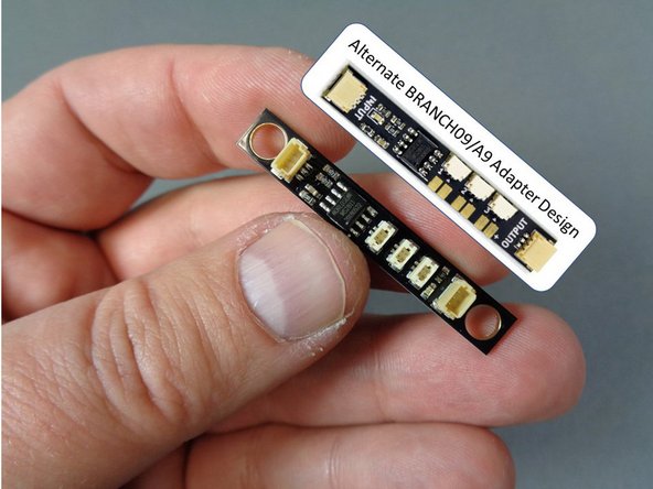
You should have one more adapter board and red 12" 3-wire cable inside the Main Control and Connecting Parts bag. As shown in the first photo for this step, that adapter board is a BRANCH09 adapter, with three small plugs and two large plugs.
-
Depending on when your kit was manufactured, the BRANCH09 adapter included with your kit may have top-facing or side-facing connectors. The photos for the step show both versions of the adapter. They operate identically.
-
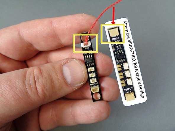
As shown by the yellow rectangle in the second photo, connect one end of the red connecting cable to the large plug on the BRANCH09 adapter board closest to the small black chip.
-
For proper operation, make sure you connect the wire to the large plug closest to the black chip. If you connect the wire to the other large plug, the green power light will still come on, but the lights connected to the BRANCH09 adapter board will not work.
-
As shown by the orange rectangle in the third photo, connect the other end of the red cable to the OUTPUT plug on the third BRANCH09X adapter board.
-
If you did not purchase interior lights with your kit, then you will have plugs #5-#9 empty on your BRANCH09X adapter. This is OK.
-
-
-
Note that some of the photos in this step show the Falcon with its top panels re-attached. Your Falcon will still have its panels removed. That is OK-- the steps are still the same.
-
Also note that the BRANCH09 adapter in your kit may have side-facing connectors instead of top-facing connectors. That is ok-- the boards operate identically.
-
As shown by the dotted blue lines in the first photo of this step, run the red wire around the center of the Falcon so the BRANCH09 adapter board sits on top of the large tan plate in the center rear.
-
If your BRANCH09 adapter has top-facing connectors, you can use two 1x1 LEGO plates from the disassembled docking bay parts you removed to install the lit Brickstuff docking bay parts, and use those to mount the adapter on the tan plate as shown in the second photo.
-
The 1x1 plates may be a tight fit into the holes on the BRANCH09 adapter board, so you may need to press firmly to attach them.
-
If your BRANCH09 adapter has side-facing connectors, you can use two small sticky squares to attach it to the tan plate as shown in the third photo.
-
-
-
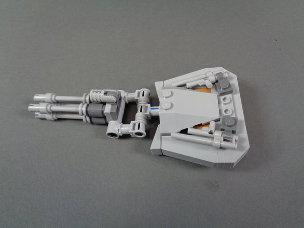
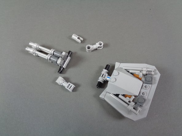
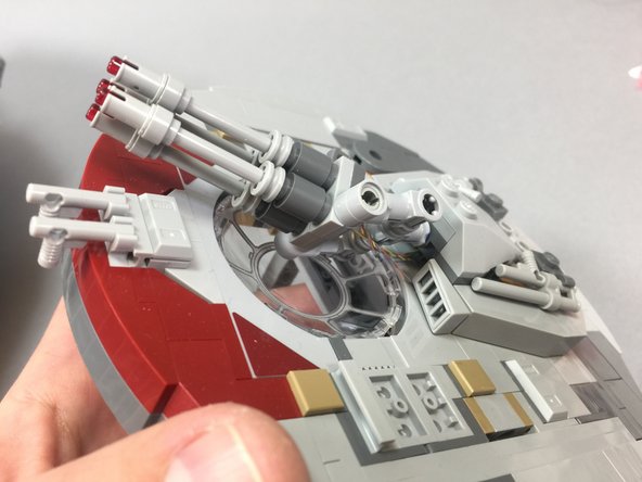
As shown in the first two photos for this step, remove the top laser cannon from the large round turret, and disassemble the cannon as shown in the second photo.
-
As shown in the third photo, take the laser cannon with pre-mounted LED lights out of its bag.
-
-
-
Depending on when your kit was manufactured, it will have one of two types of connecting plugs.
-
If your connecting plugs look like the ones in the first photo, you can skip to the next step.
-
If your connecting plugs look like the plugs in the second photo, you will need to attach the two adapter cables that were included in the same bag as your laser cannon.
-
The third photo shows how these two adapter cables should be connected. When attaching, make sure to line up the small white dots on both sides of the connecting plug.
-
-
-
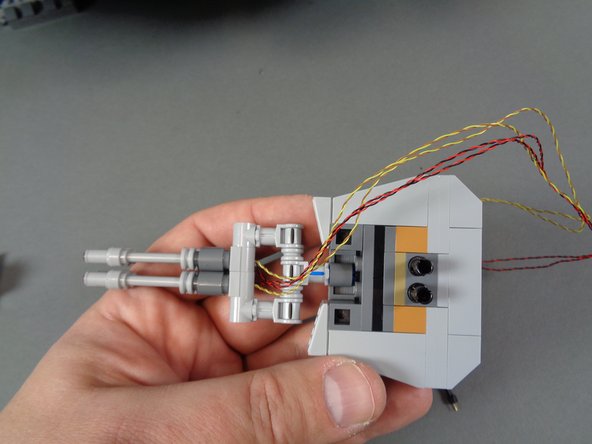
As shown in the photos for this step, mount the pre-lit laser cannon that came with your kit, re-attaching the parts you removed two steps prior.
-
Note that the laser cannon included with your kit may have different color wires, different length wires, and/or wires of different thicknesses than the wires shown in these photos. That is OK.
-
As shown in the third photo, attach the pre-lit laser cannon so the LED light wires extend out the underside of the cannon.
-
-
-
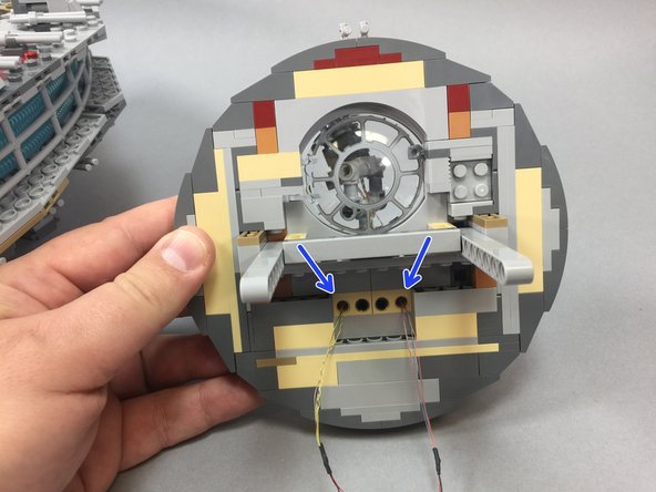
Now you will re-attach the top laser cannon to the main turret.
-
As shown by the red arrows in the first photo, pass the two pairs of LED light wires through the two OUTER Technic stud holes in the tan brick.
-
Do not pass the wires through the two inner holes, as these are used by the two black Technic pins to hold the laser cannon in place.
-
Re-attach the laser cannon to the main turret.
-
As shown in the second photo, make sure there is enough "slack" wire under the laser cannon to allow the cannon to be moved and aimed in different directions without pulling on the wires.
-
The third photo shows the underside of the main turret after the laser cannon has been re-attached. The two blue arrows show the stud holes where the two pairs of LED light wires pass through.
-
Set the laser turret assembly aside for now. You will connect the laser LED lights later.
-
-
-
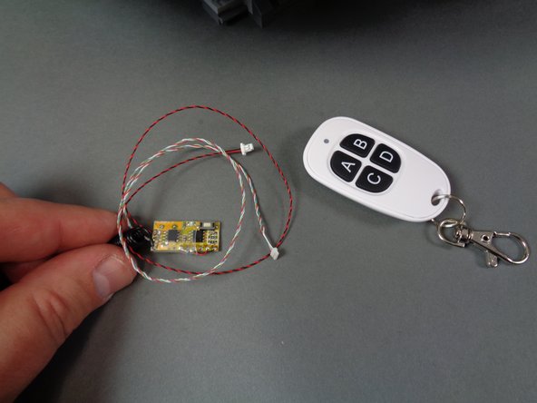
As shown in the first photo, remove the remote control transmitter and receiver from their bag.
-
As shown in the second photo, attach a large sticky square to the back side of the remote receiver. As shown by the red arrow in the second photo, you can tell the back side of the receiver by the rectangular metal crystal mounted on the back.
-
As shown in the third photo, use the sticky square to mount the remote receive on the large tan plate next to the BRANCH09 adapter board.
-
Note that the third photo shows a BRANCH09 adapter with top-facing connectors. Depending on when your kit was manufactured, the BRANCH09 adapter included with your kit may have side-facing connectors.
-
-
-
In this step, you will connect the remote receiver to the TRUNK08 master controller.
-
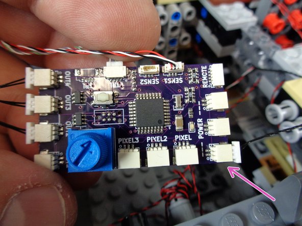
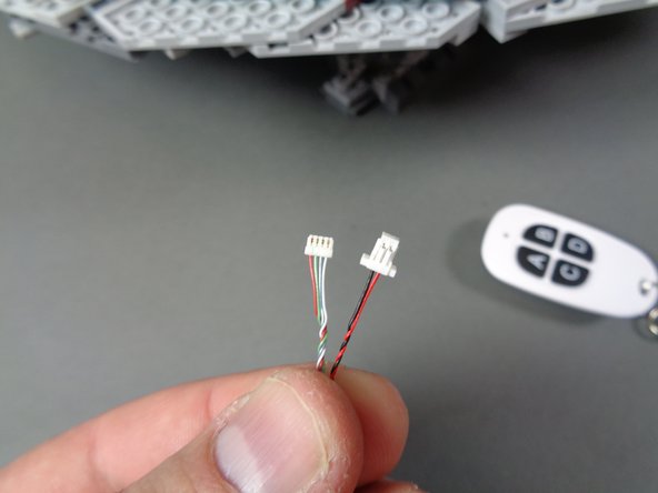
As shown in the first photo for this step, the remote receiver has two wires with two different plugs:
-
One plug is larger and has two wires (one red and one black).
-
The other plug is smaller and has four wires (red, green, blue, and white).
-
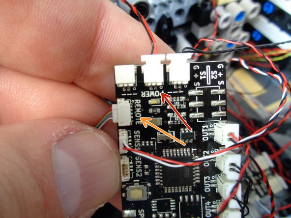
The arrows in the second and third photos show where both wires connect to the two different designs of TRUNK08 master controller.
-
The red arrow shows where the larger connector should plug in. This is the main power wire to the remote receiver.
-
The orange arrow shows where the smaller connector should plug in. This is the control wire.
-
Refer to the photo with the TRUNK08 master controller that matches the version included with your kit.
-
-
-
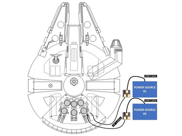
Your Falcon has two power connection points:
-
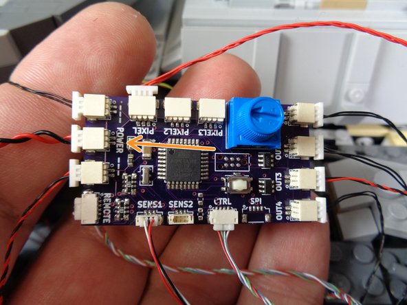
The first power wire connects to the two sound modules via the BRANCH04/A4 adapter board you connected at the beginning of the installation process. The orange arrow in the first photo shows the power connected (thicker wire) to the BRANCH04/A4 adapter board.
-
The second power input connects directly to the TRUNK08 master controller via the one remaining open large power connecting plug. See the second and third photos to identify this plug.
-
The second and third photos show the connection location for power to the two different designs of TRUNK08 master controller.
-
Refer to the photo with the TRUNK08 master controller that matches the version included with your kit.
-
If you are using the USB power sources, you can pass both USB power wires up through the bottom of the Falcon by the right rear landing gear.
-
If you are using Power Functions power sources, you can arrange the circuit boards and wires inside the right rear area to make room to store the batteries inside the Falcon.
-
You can use any spare sticky squares to mount circuit boards to the Falcon frame.
-
-
-
This step is optional, but can be helpful if you need to extend the reach of your power cables. If you are planning to power your setup using USB battery banks, remember that you will need two. We have some battery bank recommendations here.
-
Your kit includes four additional parts you can use to extend power outside the Falcon. You might want to do this, for example, if you have a diorama and you don't want the power wires to be as visible.
-
Included in your kit, there is an Extra Parts Bag. Inside that bag are the four parts you can use to extend your power sources:
-
2x BRANCH04/A4 adapter boards.
-
2x 24" two-wire connecting cables. These cables may be black or black/red, and they may be thicker than the wires shown in these photos. That is ok.
-
The illustration in this step shows how to connect these four parts to extend your power connections. You can download a high resolution copy of this illustration here.
-
The two photos in this step show the 24" connecting cables extending outside the Falcon.
-
Remember that the color of the wire may be different than the wire shown in the photo-- you may have black wires or red/black wires. Also, your wires may be thicker than the wires shown in the photo. That is ok.
-
-
-
Now it is time to re-attach the top panels on the Falcon, including the tops of the docking bays. Using the LEGO® instructions if necessary to see how to re-attach the panels, carefully re-assemble your ship.
-
As shown in the photo for this step, leave the two right rear panels detached so you can finish wiring the electronic components.
-
When re-attaching the tops of the docking bays, be very careful that no wires run over any bricks that will be re-attached. Wires can easily get pinched in this step, which could damage the LED lights. Route all wires around the sides of bricks to avoid pinching.
-
-
-
Now you will connect the two laser cannon light wires.
-
As shown in the first photo, rest the top laser turret on top of your Falcon. You should have two wires (white/blue) with Pico LED connectors coming from the underside of the top turret.
-
The second and third photos show how to connect the laser light wires for two different versions of BRANCH09 adapter (photo 2 shows an adapter with top-facing connectors and photo 3 shows an adapter with side-facing connectors). Follow the photo with the BRANCH09 adapter that matches the one included with your kit.
-
You should have one of the small plugs on the BRANCH09 adapter empty with nothing connected. This is ok.
-
-
-
Congratulations! You have finished installing your Brickstuff light and sound kit.
-
If you have installed a lower laser cannon, it will not operate until you configure the TRUNK08 controller to recognize it. We show you how to do that in Step 96 ahead. Your lower cannon will not operate until you complete this step!
-
To learn how to operate the various functions included with your kit, click to the next step.
-
To learn how to copy your own custom sounds onto the Falcon's "laser" sound module, click here.
-
THANK YOU very much for your support of our efforts. If you have any questions or problems, you can always e-mail us for help at support(at)brickstuff.com
-
Enjoy your upgraded Falcon!
-
-
-
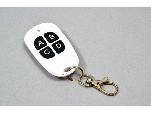
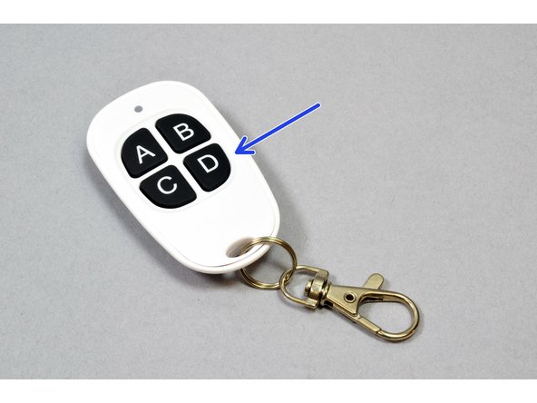
To operate the light and sound effects in your kit, you use your 4-button remote control.
-
Each button on your remote control has two functions:
-
A "short press" (pressing for less than one second) will trigger one function/action.
-
A "long press" (pressing for longer than one second) will trigger a different function/action.
-
Click to the next step to learn the functions of the "A" button on your remote control.
-
-
-
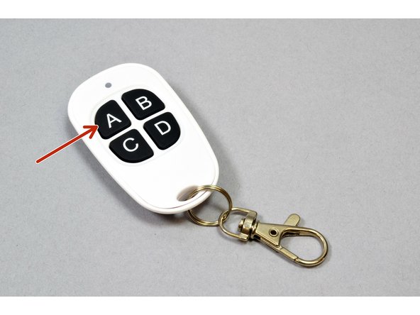
A "short press" of the "A" button on the remote control will cycle through six different exterior lighting effects:
-
1. Exterior Lights Off
-
2. Front Mandibles On
-
3. Front Mandibles + Landing Lights On
-
4. Mandibles + Landing Lights + Docking Bay Lights On (solid)
-
5. Mandibles + Landing Lights + Docking Bay Lights On (double flash)
-
6. Mandibles + Landing Lights + Docking Bay Lights On (aircraft effect)
-
A "long press" of the "A" button will turn the master power on or off for the entire Falcon. NOTE that if your Falcon lights or sounds do not respond to the remote control, your master power may be off. Try a "long press" on the "A" button to resolve the issue.
-
-
-
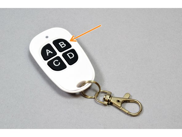
A "short press" on the remote control "B" button will toggle the Falcon's engines on and off.
-
When starting up, there is a 20% chance that the engines will fail, in which case a special light and sound sequence will play to simulate engine failure.
-
During a "normal" engine start, sounds and lights will be synchronized for a long-playing takeoff and flight sequence.
-
If you have the interior lights installed, the Hyperdrive unit will also operate in sync with the engine lights and sounds to create a highly realistic effect.
-
After the full "normal" engine start sequence has played, the engine lights will continue pulsating to simulate flight. To turn the engines off, perform another "short press" of the "B" button.
-
A "long press" on the remote control "B" button after the "normal" engine start sequence has finished playing will trigger a "flyby" sound sequence that can be repeated any number of times as long as the engines remain on.
-
Note that the engine lights need to remain on after the "normal" start sound sequence has finished playing in order to be able to access the "flyby" sound sequence.
-
-
-
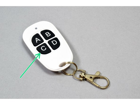
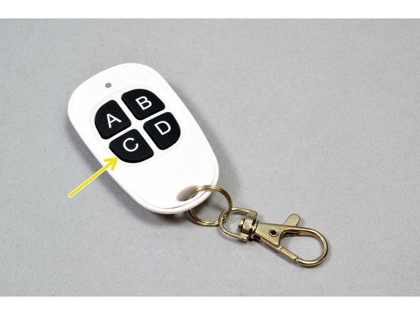
A "short press" of the "C" button will trigger a firing of the laser cannon. A random selection of 1, 2, or 6 laser blasts will be selected, and the laser will fire along with synchronized lights.
-
If you have installed the secondary add-on laser (on the underside of the Falcon) and have enabled the second laser in the main configuration, firing the laser will randomly select between firing the top or bottom cannon. See Step 101 to find out how to set your configuration to include the second laser.
-
A "long press" of the "C" button will toggle random laser firing. When random laser firing is on, the laser cannon (top or bottom randomly selected if you have both top and bottom cannons installed) will fire at random intervals. Each time before firing, telemetry sounds may also be played (determined randomly).
-
When random laser firing is activated, you will hear a special laser telemetry sound play once.
-
When random laser firing is de-activated, you will hear a single beep play once.
-
Even when random laser firing is enabled, you can still trigger manual firing of the laser anytime via a "short press" on the "C" button.
-
-
-
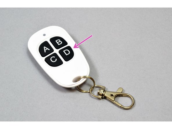
A "short press" on the "D" button will trigger playing of one of the active custom user sounds. Click here to learn how to add your own custom sounds to the Falcon's sound module.
-
Custom sounds are randomly selected for playback each time you press the "D" button.
-
When you first receive your kit, no custom sounds will be loaded, so pressing the "D" button will not trigger playback of any sounds. You will need to manually install your own custom sounds for the "D" button to have any effect.
-
Using the custom sound setup procedure described in the article accessible via the link above, you can select up to five custom sounds to randomly play back with the "D" button. You can select fewer than five sounds to be active, in which case pressing "D" will randomly select from fewer than five custom sounds.
-
A "long press" on the "D" button triggers opening/closing of the boarding ramp when our motorized boarding ramp add-on kit is installed. This is available from our website in the "Upgrades and Add-Ons" section.
-
-
-
The remote control supports two special configuration modes, each of which is accessed by holding down the given button while power is OFF to both the Falcon lights and sounds, then continuing to hold the button for 3 seconds after power has been turned on.
-
When pressed in the manner described above, the "C" button allows you to tell the TRUNK08 master controller whether you have one laser cannon (top) or two (top + bottom) installed.
-
When you hold down the "C" button at power-up time and then release, lights in the top laser cannon will begin flashing.
-
Laser lights will flash once if only one laser cannon (top) is configured.
-
Laser lights will flash twice if both a top and bottom laser cannon are configured.
-
To change the laser cannon selection, press the "A" button on the remote.
-
When you have selected the appropriate setting, press the "C" button once again on the remote to exit configuration mode. Normal lighting operation will resume and your setting will be written to memory.
-
-
-
The remote control supports two special configuration modes, each of which is accessed by holding down the given button while power is OFF to both the Falcon lights and sounds, then continuing to hold the button for 3 seconds after power has been turned on.
-
When pressed in the manner described above, the "D" button allows you to tell the TRUNK08 master controller about any custom sounds you have copied onto the "laser" sound module. Click here for full instructions covering how to copy and manage custom sound files.
-
-
-
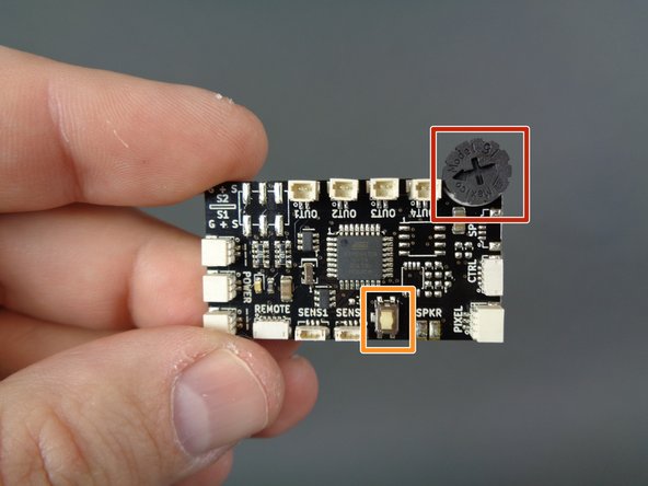
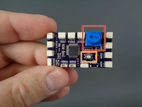
The photos in this step show both versions of the TRUNK08 master controller. Refer to the photo that matches the specific version of TRUNK08 that was included with your kit.
-
The red square shows the onboard dial. While power is turned on, you can use this dial to adjust the playback volume of all sounds. When you turn the dial, you will hear repeated tones play in the selected volume. Continue turning the dial until you reach your desired playback volume.
-
For best results, don't turn the dial too quickly.
-
The orange rectangle shows the onboard pushbutton. This button is used by the motorized boarding ramp add-on kit, which is available on our website.
-


Cancel: I did not complete this guide.
6 other people completed this guide.
Attached Documents

7 Comments
Hi, thanks for your note. This is most likely the battery in the remote needing to be replaced. We made a video showing how to accomplish this: https://youtu.be/NeABDJYy5Ko.
I bought and installed this AWESOME kit about 4 years ago. I recently moved house (internationally) and the model was unplugged for 5 months. When I got it set back up and plugged in, got a tone and the ramp lights lit, but the remote will not turn the whole kit on. I read your response from Jul 26, 2021 on a related issue and followed your instructions to no avail. When I reset the receiver, the light extinguishes and never returns. I have cycled the power several times with the same results. Please help.
I lost my remote and got a new one, yet it does not work. I cant find anywhere in the instructions how to pair the remote to the kit. GGRRRRRR!
Brian Simon - Resolved on Release Reply
Hi Brian, thanks for your message. In the instructions included with your replacement remote, the steps are listed to pair the new remote with your existing system:
Complete the following steps to pair this remote with the receiver:
1. Make sure power is turned on and the receiver’s small LED light is glowing.
2. Press the white “SET” button on the receiver for 1 second, then release.
3. Press any button on your new remote transmitter. The small LED light on the receiver should blink several times, indicating that it is now paired with the new remote.
Each receiver can store up to 10 remote pairing codes, so multiple remotes can control one receiver.
If you ever want to erase all pairing codes from a receiver’s memory, hold down the white button for 10 seconds, until the receiver’s LED light blinks, then complete the steps above to pair the new remote.
I hope this helps— please let me know if you have trouble getting the transmitter and receiver to connect.
Thank you.
Rob K -