-
-
In addition to a good soldering iron, we recommend also having some soldering flux on hand, along with a good pair of angle-cut clippers and a good pair of tweezers. We use the Xuron XUR410T sprue cutter and the Wiha 44518 tweezers.
-
-
-
This is a full panel of Pico LEDs (120 in total). You may have purchased less than a full panel, but this photo shows how each Pico LED is attached to the panel with two "fingers"-- one on the top of each Pico LED and one on the bottom.
-
-
-
Each Pico LED has small markings above the copper pads-- one for positive ("+") and one for negative ("-"). We recommend orienting the Pico LEDs so the markings are on top as you solder-- this ensures that you know the + leads are on the left and - on the right.
-
-
-
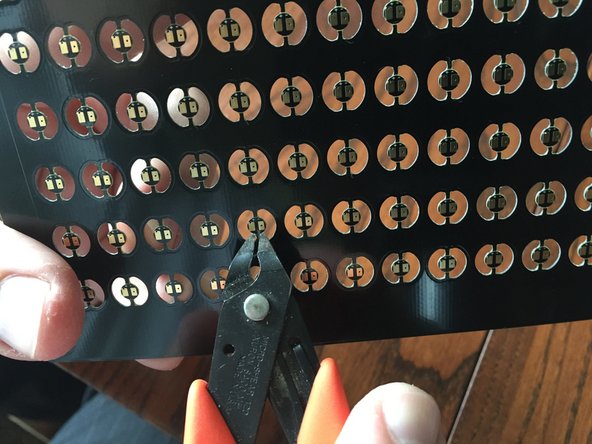
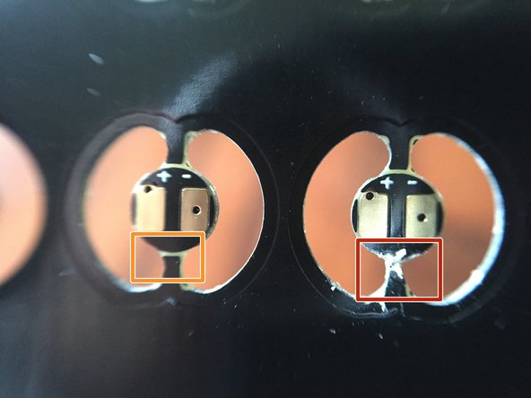
Before soldering wires to the Pico LED Light Boards, we recommend pre-cutting the bottom "finger" on each light board-- this will make it easier later to separate the light board from the panel without needing to stress or bend the wire after soldering.
-
The orange and red boxes in the second photo show an uncut finger (orange box) and a cut finger (red box).
-
Make sure to cut ALL lower fingers on the LED panel BEFORE soldering.
-
-
-
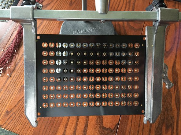
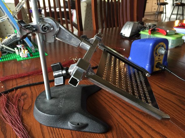
After you have pre-cut all lower fingers on the LED panel, secure the panel for soldering. We use the Panavise 333 Rapid Assembly Circuit Board Holder.
-
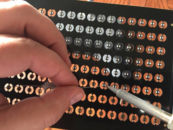
After securing the PC board panel, apply a liberal amount of solder to each copper pad. Here it is best to over-apply solder, but make sure you don't cause a short circuit by bridging the pads.
-


